EP0364201A1 - Kiln car superstructure - Google Patents
Kiln car superstructure Download PDFInfo
- Publication number
- EP0364201A1 EP0364201A1 EP89310325A EP89310325A EP0364201A1 EP 0364201 A1 EP0364201 A1 EP 0364201A1 EP 89310325 A EP89310325 A EP 89310325A EP 89310325 A EP89310325 A EP 89310325A EP 0364201 A1 EP0364201 A1 EP 0364201A1
- Authority
- EP
- European Patent Office
- Prior art keywords
- members
- refractory
- kiln car
- horizontally extending
- superstructure
- Prior art date
- Legal status (The legal status is an assumption and is not a legal conclusion. Google has not performed a legal analysis and makes no representation as to the accuracy of the status listed.)
- Withdrawn
Links
Images


Classifications
-
- F—MECHANICAL ENGINEERING; LIGHTING; HEATING; WEAPONS; BLASTING
- F27—FURNACES; KILNS; OVENS; RETORTS
- F27D—DETAILS OR ACCESSORIES OF FURNACES, KILNS, OVENS, OR RETORTS, IN SO FAR AS THEY ARE OF KINDS OCCURRING IN MORE THAN ONE KIND OF FURNACE
- F27D5/00—Supports, screens, or the like for the charge within the furnace
- F27D5/0006—Composite supporting structures
-
- F—MECHANICAL ENGINEERING; LIGHTING; HEATING; WEAPONS; BLASTING
- F27—FURNACES; KILNS; OVENS; RETORTS
- F27D—DETAILS OR ACCESSORIES OF FURNACES, KILNS, OVENS, OR RETORTS, IN SO FAR AS THEY ARE OF KINDS OCCURRING IN MORE THAN ONE KIND OF FURNACE
- F27D3/00—Charging; Discharging; Manipulation of charge
- F27D3/12—Travelling or movable supports or containers for the charge
- F27D3/123—Furnace cars
Landscapes
- Engineering & Computer Science (AREA)
- Mechanical Engineering (AREA)
- General Engineering & Computer Science (AREA)
- Furnace Charging Or Discharging (AREA)
Abstract
A kiln car superstructure (40) comprises uprights (41) each formed of two or more hollow vertical members (42a,42b) connected together in end-to-end relationship by coupling members (43) affording spigots (44) which enter into the hollow members (42a,42b). The vertical members are formed as extrusions of ceramic material whilst the coupling members are formed as pressings. The coupling members (43) are each formed with a transverse opening (45) to receive horizontally extending members (46) which in turn support further horizontally extending members (47) at right angles thereto.
Description
- This invention relates to kiln cars for use in supporting ceramic ware for firing in a refractory kiln. Such kiln cars normally comprise a non-refractory trolley which carries a refractory base structure which serves largely to insulate the trolley thermally from the high temperature which exists in the kiln, and a refractory superstructure on which ceramic ware is supported. This invention is more specifically concerned with the refractory superstructure of such kiln cars.
- Many types of superstructure have been used in the past, but where it is required to support ware at several superposed levels, the superstructure usually includes a plurality of upright elements which are supported substantially rigidly at their lower ends within the base structure of the kiln car. Such upright elements, either directly or indirectly, carry further, horizontal elements which define supporting surfaces on which the ware is placed for firing.
- Such multi-level superstructures may have a height of some 2 to 3 metres or more above the base structure and may be required to carry very heavy loads. Accordingly, it is necessary to give a substantial degree of rigidity to the superstructure. In some cases this has been achieved by utilising upright elements of which at least one component extends over the full height of the superstructure. In other cases the upright elements are made from several superposed and interconnected sections, in which case they are also interconnected substantially rigidly by transverse members forming part of the horizontally disposed ware-carrying structure.
- One example of the former arrangement is shown in GB2138115 and one example of the latter in GB2151005.
- However, in practice it is difficult, and hence expensive, to manufacture one-piece uprights in continuous lengths greater than about 2 metres without significant deviations from the desired degree of straightness in the case of designs of the former type. Whilst in designs of the latter type it is difficult, and hence expensive, to ensure that the various components of the superstructure interfit sufficiently accurately for the required degree of rigidity to be achieved. This is largely due, in both cases, to dimensional variations introduced during firing of the components.
- Additionally, it is increasingly being recognised that it is desirable to minimise the thermal mass of the superstructure as well as of the base structure, in order to minimise the heat energy absorbed by the refractory material of which they are made, rather than by the ware being fired.
- Various lightweight superstructures have been proposed, relying for example on the use of hollow section elements, but the problems of accurate interfitting of such elements remain. Thus, in one simple arrangement, hollow section continuous upright elements are formed with apertures at spaced intervals for the reception of cross-members. However, if the required apertures are formed in the upright elements after they have been fired, this requires a time consuming and costly operation using diamond-tipped tools. Alternatively, if the apertures are formed in the unfired material, the final dimensions are subject to excessive variations and a good-fit for the cross-members cannot be guaranteed. Additionally, in both cases, the strength of the upright element is impaired and it may also be physically damaged at the site of the apertures.
- It is an object of the invention to provide a novel design of kiln car superstructure which reduces or eliminates such disadvantages. According to the invention, a kiln car superstructure comprises:-
- (a) a plurality of upright elements arranged in rows and each formed from a plurality of superposed, hollow vertical refractory members joined in end-to-end relation by means of refractory coupling members affording respective spigot portions which are received within the hollow vertical members thereby joined, the coupling members each being formed with a transversely extending opening intermediate said spigot portions; and
- (b) a plurality of horizontally extending members each of which extends through the openings in a plurality of said coupling members arranged at the same level in respective ones of said upright elements in one of said rows.
- Preferably, the vertical members are formed from extruded ceramic material which is cut to the required length before firing, and may if necessary be machined after firing to the exact length required.
- The coupling members are preferably formed by pressing or moulding and thereby have a closer dimensional tolerance than can be achieved for extruded components.
- To ensure improved rigidity, the length of the spigots entering the hollow vertical members is preferably significantly greater than the maximum cross-sectional dimension of said spigots, which are a close-fit within the vertical members.
- The horizontally extending members may extend either longitudinally or transversely of the length of the superstructure, or in different directions at different levels. The superstructure may comprise further horizontally extending members which rest on the aforesaid horizontally extending members; in use the ware for firing may rest directly on said further horizontally extending members, or on flat refractory plates (usually called "bats") resting on said further horizontally extending members, or on the first mentioned horizontally extending members.
- Within the base structure, the lower end of each upright element may be secured by being clamped between a pair of metal plates, one of which is fixed in position, for example by being secured to a metal strap carried by the trolley on which the refractory structure is supported.
- These and other aspects of the invention will now be described by way of example with reference to the accompanying drawings wherein:-
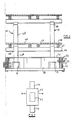
- FIGURE 1 shows a side view of a kiln car incorporating a refractory superstructure in accordance with the invention;
- FIGURE 2 shows a transverse section on the line II-II, omitting the trolley on which the ceramic structure is carried;
- FIGURE 3 shows a side view of a coupling member used in the construction of the superstructure;
- FIGURE 4 illustrates an alternative form of upright element which may be used in the construction of a refractory superstructure in accordance with the invention; and
- FIGURE 5 illustrates a further alternative embodiment of upright element.
- As illustrated in Figure 1, a
kiln car 10 comprises a conventional wheeled,metal trolley 11 which supports arefractory base structure 20 and a refractory, ware-carryingsuperstructure 40. - The base structure 20 (which does not form part of the present invention) rests on a concrete or other refractory
top plate 12 carried by thetrolley 11 and comprises a plurality ofuprights posts 21 arranged peripherally of the trolley withvertical wall plates 22 located between adjacent posts to define a hollow base which is filed with lightweight insulating material (not shown). In the illustrated embodiment, the longitudinal sides of thebase structure 20 also include outwardly projectingbaffles 23 to limit the downward transmission of radient heat from the hot zone of the kiln to the lower zone in which thenon-refractory trolley 11 is located. - The top of the
base structure 20 is closed by means ofrefractory plates 24 which rest on the upper edges of theposts 21 andwall plates 22 and are further supported as necessary byadditional posts 25 provided at appropriate locations internally of the base structure. - The
superstructure 40, in accordance with the invention, comprises in the illustrated embodiment a plurality ofuprights 41 each comprising a pair of superposed vertical members 42a and 42b joined byrespective coupling members 43. Eachcoupling member 43, as most clearly seen in Figure 3 is formed with upwardly and downwardly extending spigots 44 which are received as a close-fit within the vertical members 42a,42b which are themselves hollow. - An opening 45 is formed centrally within each
coupling member 43 and transversely extendinghorizontal members 46 extend through the aligned openings 45 to form cross-bearers, which in turn support horizontal longitudinally extendingmembers 47. Flat,ceramic plates 48 may be supported on thelongitudinal members 47 and the ware to be fired can then be placed on such plates. Alternatively, in some cases the ware may rest directly on thelongitudinal members 47, or on thetransverse members 46. - The
vertical members 42 may be formed by extrusion to a hollow box section and cut to the required lengths before firing. If necessary, after firing the ends of such members may be machined to provide accurately level faces and a precisely controlled length. - In a typical case, the internal dimensions of the upright members in this way may have a dimensional tolerance of approximately ± 1.5 mm.
- The
horizontal members - However, the
coupling members 43 are formed as pressings or mouldings and in this way can be formed to a greater dimensional accuracy, typically ± 0.5 mm. - Thus, the spigots 44 can reliably be made to dimensions which fit quite snugly within the hollow vertical members, and by ensuring that the length of each spigot is significantly greater than its maximum cross-sectional dimensions, possible mis-alignment betwen the longitudinal centre lines of the superposed vertical members is reduced to a minimum, with the result that the entire upright 41 is sufficiently stable despite the fact that it is constructed from a plurality of superposed components and without a single component extending over its entire height.
- Likewise, the accuracy with which the openings 45 in the
coupling members 43 can be produced ensures that thetransverse members 46 can be located accurately and interfit with the required degree of precision to impart stability to the superstructure without the need for complicated interfitting formations on the components. - In the embodiment illustrated in Figures 1 and 2, the
uprights 41 comprise only two superposed vertical members 42a and 42b and the latter carry at their upper endstop members 50 which include downwardly projectingspigots 51 to enter within the hollow vertical members 42b, and at their upper faces a groove 52 to receive further transverse members 46a, which in turn support furtherlongitudinal members 47a carrying further plates 48a if required. Whilst in Figures 1 and 2 thetop members 50 as illustrated are of a conventional design with only a relativelyshort projection 51, it will be appreciated that the top members may be formed so as to be generally similar to thecoupling members 43 but without the upper portion above the line A-A in Figure 3 so as to provide improved support for thetransverse members 47a. As a further alternative, the uppermosttransverse members 47a could be supported byfurther coupling members 43 carried at the upper ends of the vertical members 42a. - To ensure that the
uprights 41 are each sufficiently stable relative to thetrolley 11, the lowermost vertical members 42a extend into and through thehollow base 20 and are held in position therein by a suitable structure. The preferred arrangement, as in the illustrated embodiment, includes a pair ofmetal clamping plates 13 which embrace the lower end portion of the lowermost vertical member 42a and are tightened onto the latter by any suitable means, for example threaded fastening elements or spring clips. One clamping plate of each pair is fixed, as by welding, to a metal base plate or strip provided at the upper face of thetrolley 11. - Whilst in the embodiment illustrated in Figures 1 and 2 the
uprights 41 comprise only two superposed vertical members and superstructure affords only two levels of ware-supporting plates, the number of ware-supporting levels and the overall height of the superstructure may be significantly increased without loss of stability. - By way of example, Figure 4 illustrates an upright 41a which comprises five vertical members 42c, 42d, 42e, 42f, 42g, interconnected by means of four
coupling members 43, so as to provide withtop member 50 five ware-supporting levels and an overall height of substantially over 2 metres. In the embodiment illustrated in Figure 4, the vertical members are of varying lengths in order to provide ware-supporting levels at different spacings so that the superstructure is specifically tailored for a particular, mixed load. It will be appreciated that the vertical members are relatively inexpensive to produce and can therefore be manufactured in a wide range of different lengths to enable superstructures to be built in accordance with a wide range of users requirements, without the need for expensive, custom designed components. - Figure 5 illustrates a further alternative form of upright 41b which is of the same height as that illustrated in Figure 4, but includes only two vertical members, 42h and 42i connected by a
single coupling member 43. However, in this case the vertical members 42h and 42i are formed with cut-outs 49 at various positions throughout their lengths for the reception oftransverse members 46 in addition to those which would extend through the opening 45 of the coupling member. Whilst this embodiment to some extent retains the disadvantages of forming cut-outs in the upright members, it nevertheless retains the advantages of enabling the overall height of the upright to be increased beyond that which can readily be obtained if it is made in one piece. - Whilst in the embodiment illustrated in Figures 1 and 2 the
coupling members 43 are so arranged as to support transversely extendinghorizontal members 46, it will be appreciated that they may alternatively be designed to support longitudinally extending horizontal members, or that in the same structure the coupling members at different levels may support horizontal members extending in different directions, for example alternatively transversely and longitudinally. - A kiln car superstucture constructed in accordance with the invention has the advantage that the components are relatively simple to manufacture, the structure is stable and can more readily be assembled to a greater height than other superstructure construction systems allow with safety, and that it can readily be modified at any time by interchanging components so that it can readily be adapted to changing requirements of the user in a manner which is not possible with other types of construction.
Claims (10)
1. A kiln car superstructure comprising:-
(a) a plurality of upright elements (41) arranged in rows and each formed from a plurality of superposed, hollow vertical refractory members (42a, 42b; 42c-42g; 42h, 42i) joined in end-to-end relation by means of refractory coupling members (43) affording respective spigot portions (44) which are received within the hollow vertical members thereby joined, the coupling members (43) each being formed with a transversely extending opening (45); and
(b) a plurality of horizontally extending members (46) each of which extends through the openings (45) of a plurality of said coupling members (43) arranged at the same level in respective ones of said upright elements (41) in one of said rows.
2. A kiln car superstructure according to Claim 1 wherein the vertical members (41) are formed from extruded ceramic material which is cut to the required length before firing.
3. A kiln car superstructure according to Claim 1 or Claim 2 wherein the coupling members (43) are formed by pressing or moulding.
4. A kiln car superstructure according to Claim 1 wherein the length of the spigot portions (44) entering the vertical members is significantly greater than the maximum cross-sectional dimensions of such spigot portions.
5. A kiln car superstructure according to Claim 1 wherein the horizontally extending members (46) extend transversely of the length of the superstructure.
6. A kiln car superstructure according to Claim 1 wherein horizontally extending members extend longitudinally of the length of the superstructure.
7. A kiln car superstructure according to Claim 1 wherein the horizontally extending members (46) support further horizontally extending members (47) arranged transversely thereto.
8. A kiln car superstructure according to Claim 7 wherein said further horizontally extending members (47) support flat refractory plates (48).
9. A kiln car superstructure according to Claim 1 wherein the lowermost vertical members (42a;42c;42h) of said upright elements (41) extend into an through a refractory base structure (20) and are secured in position between pairs of clamping plates (13).
10. A kiln car comprising a non-refractory trolley (11) carrying a refractory base structure (20) and a refractory ware-carrying superstructure comprising:-
(a) a plurality of upright elements (41) arranged in rows and each formed from a plurality of superposed, hollow vertical refractory members (42a,42b;42c-42g; 42h,42i) joined in end-to-end relation by means of refractory coupling members (43) affording respective spigot portions (44) which are received within the hollow vertical members thereby joined, the coupling members (43) each being formed with a transversely extending opening (45); and
(b) a plurality of horizontally extending members (46) each of which extends through the openings (45) of a plurality of said coupling members (43) arranged at the same level in respective ones of said upright elements (41) in one of said rows.
Applications Claiming Priority (2)
| Application Number | Priority Date | Filing Date | Title |
|---|---|---|---|
| PCT/GB1988/000860 WO1990004146A1 (en) | 1988-10-10 | 1988-10-10 | Kiln car superstructure |
| WOPCT/GB88/00860 | 1988-10-10 |
Publications (1)
| Publication Number | Publication Date |
|---|---|
| EP0364201A1 true EP0364201A1 (en) | 1990-04-18 |
Family
ID=10629999
Family Applications (1)
| Application Number | Title | Priority Date | Filing Date |
|---|---|---|---|
| EP89310325A Withdrawn EP0364201A1 (en) | 1988-10-10 | 1989-10-10 | Kiln car superstructure |
Country Status (2)
| Country | Link |
|---|---|
| EP (1) | EP0364201A1 (en) |
| WO (1) | WO1990004146A1 (en) |
Cited By (5)
| Publication number | Priority date | Publication date | Assignee | Title |
|---|---|---|---|---|
| EP0463290A1 (en) * | 1990-06-26 | 1992-01-02 | Norton Gmbh | Furnace wagon with replaceable support elements |
| CN102538452A (en) * | 2012-01-20 | 2012-07-04 | 广东摩德娜科技股份有限公司 | Portable and energy-saving kiln car of tunnel kiln |
| FR2976543A1 (en) * | 2011-06-15 | 2012-12-21 | Ceritherm | Wagon frame for transporting products in high temperature furnace in ceramic industry, has notches allowing embedding plates between notches for providing assembly of flat profiles that mechanically collaborate with each other |
| US10030910B2 (en) | 2013-10-07 | 2018-07-24 | Saint-Gobain Ceramics & Plastics, Inc. | Refractory article |
| EP3259545A4 (en) * | 2015-02-17 | 2018-11-14 | H. C. Starck Inc | Racks for high-temperature metal processing |
Families Citing this family (3)
| Publication number | Priority date | Publication date | Assignee | Title |
|---|---|---|---|---|
| DE19639531C1 (en) * | 1996-09-26 | 1998-02-05 | Riedhammer Gmbh Co Kg | Loading and unloading device for a firing rack |
| CN102636032A (en) * | 2012-05-05 | 2012-08-15 | 于宗亮 | Adjustable kiln car |
| CN116853752B (en) * | 2023-07-24 | 2024-01-16 | 山东中和金石科技集团股份有限公司 | Inorganic nonmetallic material fires material feeding unit |
Citations (5)
| Publication number | Priority date | Publication date | Assignee | Title |
|---|---|---|---|---|
| GB534546A (en) * | 1940-02-20 | 1941-03-10 | Wedgwood & Sons Ltd Josiah | Apparatus for use in the firing of pottery ware |
| EP0067451A1 (en) * | 1981-06-16 | 1982-12-22 | Hubertus Dr. Peter | Tunnel kiln truck |
| GB2136100A (en) * | 1983-03-09 | 1984-09-12 | Norton Co | Firing carriage including a rack structure of refractory material for the ceramics industry |
| DE8801017U1 (en) * | 1988-01-28 | 1988-03-10 | Sigri Gmbh, 8901 Meitingen, De | |
| DE8802708U1 (en) * | 1988-03-01 | 1988-04-28 | Sigri Gmbh, 8901 Meitingen, De |
-
1988
- 1988-10-10 WO PCT/GB1988/000860 patent/WO1990004146A1/en unknown
-
1989
- 1989-10-10 EP EP89310325A patent/EP0364201A1/en not_active Withdrawn
Patent Citations (5)
| Publication number | Priority date | Publication date | Assignee | Title |
|---|---|---|---|---|
| GB534546A (en) * | 1940-02-20 | 1941-03-10 | Wedgwood & Sons Ltd Josiah | Apparatus for use in the firing of pottery ware |
| EP0067451A1 (en) * | 1981-06-16 | 1982-12-22 | Hubertus Dr. Peter | Tunnel kiln truck |
| GB2136100A (en) * | 1983-03-09 | 1984-09-12 | Norton Co | Firing carriage including a rack structure of refractory material for the ceramics industry |
| DE8801017U1 (en) * | 1988-01-28 | 1988-03-10 | Sigri Gmbh, 8901 Meitingen, De | |
| DE8802708U1 (en) * | 1988-03-01 | 1988-04-28 | Sigri Gmbh, 8901 Meitingen, De |
Cited By (6)
| Publication number | Priority date | Publication date | Assignee | Title |
|---|---|---|---|---|
| EP0463290A1 (en) * | 1990-06-26 | 1992-01-02 | Norton Gmbh | Furnace wagon with replaceable support elements |
| FR2976543A1 (en) * | 2011-06-15 | 2012-12-21 | Ceritherm | Wagon frame for transporting products in high temperature furnace in ceramic industry, has notches allowing embedding plates between notches for providing assembly of flat profiles that mechanically collaborate with each other |
| CN102538452A (en) * | 2012-01-20 | 2012-07-04 | 广东摩德娜科技股份有限公司 | Portable and energy-saving kiln car of tunnel kiln |
| US10030910B2 (en) | 2013-10-07 | 2018-07-24 | Saint-Gobain Ceramics & Plastics, Inc. | Refractory article |
| US11340018B2 (en) | 2013-10-07 | 2022-05-24 | Saint-Gobain Ceramics & Plastics, Inc. | Refractory article |
| EP3259545A4 (en) * | 2015-02-17 | 2018-11-14 | H. C. Starck Inc | Racks for high-temperature metal processing |
Also Published As
| Publication number | Publication date |
|---|---|
| WO1990004146A1 (en) | 1990-04-19 |
Similar Documents
| Publication | Publication Date | Title |
|---|---|---|
| AU637665B2 (en) | Method and apparatus for erecting a glass block wall | |
| US5024035A (en) | Building block and structures formed therefrom | |
| GB2131061A (en) | Block | |
| EP0364201A1 (en) | Kiln car superstructure | |
| US4407106A (en) | Complex column | |
| US20090211195A1 (en) | Ceiling Formwork System | |
| CA1231827A (en) | Kiln car furniture module(s) | |
| US4723384A (en) | Rapid-construction framework, especially of steel, as support structure for ceiling and wall plates of a building | |
| EP0208249B1 (en) | Kiln cars | |
| GB2230799A (en) | Fire resistant curtain facade | |
| US4696140A (en) | Connector guide system for construction walls | |
| CA1295843C (en) | Casing for making concrete construction components | |
| JPS59197792A (en) | Truck for baking with refractory material shelf structure for ceramic industry | |
| US4721459A (en) | Modular, insulating kiln car top | |
| US4577727A (en) | Scaffold for the construction of round buildings of concrete or the like | |
| JPH11107440A (en) | Wall surface panel for building construction | |
| US4836777A (en) | Kiln cars | |
| US4979895A (en) | Process for firing ceramic shaped bodies and firing tools used therefor | |
| ES296275U (en) | Reinforced roof support | |
| US6142774A (en) | Support for a ceramic wagon superstructure for supporting molded blanks of ceramic material to be fired | |
| EP0192792B1 (en) | Radiation panel | |
| EP0002193A1 (en) | Supporting structure for the single-layer firing of ceramic wares | |
| EP0325671A1 (en) | Fire chariot superstructure | |
| JPS59138668A (en) | Support frame for supporting structure | |
| GB2145212A (en) | Chimney structures |
Legal Events
| Date | Code | Title | Description |
|---|---|---|---|
| PUAI | Public reference made under article 153(3) epc to a published international application that has entered the european phase |
Free format text: ORIGINAL CODE: 0009012 |
|
| AK | Designated contracting states |
Kind code of ref document: A1 Designated state(s): DE ES FR IT NL |
|
| 17P | Request for examination filed |
Effective date: 19901018 |
|
| 17Q | First examination report despatched |
Effective date: 19920828 |
|
| STAA | Information on the status of an ep patent application or granted ep patent |
Free format text: STATUS: THE APPLICATION IS DEEMED TO BE WITHDRAWN |
|
| 18D | Application deemed to be withdrawn |
Effective date: 19931025 |