EP0363328B1 - Werkzeugmaschinenspindel - Google Patents
Werkzeugmaschinenspindel Download PDFInfo
- Publication number
- EP0363328B1 EP0363328B1 EP89810759A EP89810759A EP0363328B1 EP 0363328 B1 EP0363328 B1 EP 0363328B1 EP 89810759 A EP89810759 A EP 89810759A EP 89810759 A EP89810759 A EP 89810759A EP 0363328 B1 EP0363328 B1 EP 0363328B1
- Authority
- EP
- European Patent Office
- Prior art keywords
- spindle
- frame
- spindle body
- piston
- cylinder
- Prior art date
- Legal status (The legal status is an assumption and is not a legal conclusion. Google has not performed a legal analysis and makes no representation as to the accuracy of the status listed.)
- Expired - Lifetime
Links
Images
Classifications
-
- B—PERFORMING OPERATIONS; TRANSPORTING
- B23—MACHINE TOOLS; METAL-WORKING NOT OTHERWISE PROVIDED FOR
- B23Q—DETAILS, COMPONENTS, OR ACCESSORIES FOR MACHINE TOOLS, e.g. ARRANGEMENTS FOR COPYING OR CONTROLLING; MACHINE TOOLS IN GENERAL CHARACTERISED BY THE CONSTRUCTION OF PARTICULAR DETAILS OR COMPONENTS; COMBINATIONS OR ASSOCIATIONS OF METAL-WORKING MACHINES, NOT DIRECTED TO A PARTICULAR RESULT
- B23Q1/00—Members which are comprised in the general build-up of a form of machine, particularly relatively large fixed members
- B23Q1/0009—Energy-transferring means or control lines for movable machine parts; Control panels or boxes; Control parts
- B23Q1/0018—Energy-transferring means or control lines for movable machine parts; Control panels or boxes; Control parts comprising hydraulic means
-
- B—PERFORMING OPERATIONS; TRANSPORTING
- B23—MACHINE TOOLS; METAL-WORKING NOT OTHERWISE PROVIDED FOR
- B23B—TURNING; BORING
- B23B31/00—Chucks; Expansion mandrels; Adaptations thereof for remote control
- B23B31/02—Chucks
- B23B31/24—Chucks characterised by features relating primarily to remote control of the gripping means
- B23B31/30—Chucks characterised by features relating primarily to remote control of the gripping means using fluid-pressure means in the chuck
- B23B31/302—Hydraulic equipment, e.g. pistons, valves, rotary joints
-
- F—MECHANICAL ENGINEERING; LIGHTING; HEATING; WEAPONS; BLASTING
- F16—ENGINEERING ELEMENTS AND UNITS; GENERAL MEASURES FOR PRODUCING AND MAINTAINING EFFECTIVE FUNCTIONING OF MACHINES OR INSTALLATIONS; THERMAL INSULATION IN GENERAL
- F16L—PIPES; JOINTS OR FITTINGS FOR PIPES; SUPPORTS FOR PIPES, CABLES OR PROTECTIVE TUBING; MEANS FOR THERMAL INSULATION IN GENERAL
- F16L39/00—Joints or fittings for double-walled or multi-channel pipes or pipe assemblies
- F16L39/04—Joints or fittings for double-walled or multi-channel pipes or pipe assemblies allowing adjustment or movement
Definitions
- the present invention relates generally to a machine tool spindle comprising a frame, a spindle body rotating in the frame and a clamping device associated with the spindle body.
- spindles of this kind are used either as a headstock in lathes or as a tool holder when it comes to supporting a rotating tool and driving it in rotation.
- the spindles can be associated with machine tools of different types and in particular with complex machining centers.
- the subject of the present invention is a machine tool spindle comprising a frame, a spindle body rotating in the frame on two rolling bearings spaced axially from each other, and a clamping device associated with the spindle body, and itself comprising a piston movable in a cylinder and means for supplying the cylinder with control fluid, said supply means comprising a distributor placed between said bearings in the frame, connected, on the one hand, to fixed inlet and outlet ducts drilled in the frame and, on the other hand, rotary ducts corresponding to the fixed ducts formed in the spindle body, said distributor coaxially surrounding the spindle body.
- a spindle of this kind is known in particular from the document US-3,020,057 mentioned above.
- the invention aims to remedy the drawbacks and defects of known devices by creating an improved machine tool spindle, in which means for controlling the piston by compressed air constitute a compact unit, centered and balanced with respect to the axis of the spindle body, allowing a reduction of the masses in rotary movement.
- the invention also aims to create a construction making it possible to achieve these objectives while being adaptable both to lathe dolls and to tool-holder spindles in machining centers of varied construction.
- the machine tool spindle according to the invention is characterized in that the control fluid is compressed air and said distributor consists of a single piece fixed in a bore of the frame and having a cylindrical outer surface of same diameter as a corresponding surface of the fixed part of one of said bearings.
- the supply means could have been housed between the bearings of the spindle body, balancing of the spindle is perfectly possible.
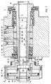
- FIG. 1 is an axial section view of this lathe doll
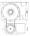
- FIG. 2 is a front elevation view in the direction of arrow A in FIG. 1.
- the drawing shows the doll frame 1 which is adjusted and fixed to the base 2 of a lathe, this lathe being designed so as to machine parts at the front end of a bar of material which passes through the doll and which is fixed and driven in rotation by the spindle, the essential elements of which will now be described.
- the frame 1 comprises a cylindrical passage 3 in which are mounted two double ball bearings 4 and 5 and outside these bearings auxiliary devices 6 and 7 for positioning and retaining oil.
- the bearings 4 and 5 are used to support a spindle body 8 whose construction is standardized and which comprises, in particular at its front end, bores 9 and 10 arranged so as to receive a clamping cone (not shown) cooperating with a clamp allowing attachment to the spindle body of the workpieces or of the front end of a work bar housed inside the spindle body 8.
- This clamp is connected, in a manner known per se, to a clamping sleeve 11 which is a tubular part passing through the internal bore of the spindle body 8 and fixed, by means of a threaded sleeve 12, to a piston 13 which is situated behind the frame 1.
- This piston 13 is engaged at the interior of a cylinder 14 consisting of a rear bottom 15, a front bottom 16 and a circular side wall 17, of a part with the bottom 15.
- This front bottom 16 is integral with a circular part 18 which forms a pulley and which is connected by a belt 19 to a motor, generally designated by 20, fixed on a console 21.
- the cylinder 14 extends overhang at the rear of the spindle body 8 to which it is fixed by screws 22, but, as will be seen, the length of the overhang and the value masses thus supported are kept at minimum values thanks to the special arrangement provided for the means for supplying the cylinder with compressed air.
- These means essentially comprise a distributor 23 which is a tubular part, with rectangular profile, fixed in the bore 3 by means of pivot screws 24 and 25. This part is centered relative to the bore 3, by a slight driving . Its internal bore is adjusted with a precision of a few micrometers.
- the distributor 23 comprises, in its external cylindrical face, two grooves 26 and 27 of rectangular profile, formed on the periphery of the external face, at a some distance from each other. In the bottom of each of these grooves 26 and 27 are provided radial passages 28 which terminate in the bottom of internal grooves 29 and 30, themselves formed in the internal bore of the part 23 at the same axial dimensions as the grooves 26 and 27.
- the grooves 26 and 27 are supplied, through the frame 1, by conduits 31 and 32 drilled in the frame 1 and the upper end of which is connected by means not shown to a reversing valve itself connected to a compressed air source and an exhaust opening.
- the groove 29 communicates with a conduit 33 formed from a series of bores made in the spindle body 8 and leading to an orifice 34 in the rear face of the spindle body 8.
- the groove 30 communicates with a conduit 35, also formed by a series of bores ending in the face 34 of the spindle body 8.
- two conduits 36 and 37 formed of series of bores, connected to the conduits 33 and 35 by seals and terminating one (33) in the rear bottom wall of the cylinder 14 and the other (35) in the front bottom wall of this cylinder.
- the air supply holes in the distributor 23 are strongly spaced from each other, so that one can tolerate a play between the distributor and the moving part relative to it. This results in the elimination of the risk of seizure without compromising operating safety due to an untimely pressure drop.
- the clearance is a few hundredths of a millimeter. This is in addition to the effects of mass reduction and reduction of the overhang and also contributes to better conditions for turning at high speeds and maintaining machining precision.
- the spindle body can be equipped with a standardized spindle nose allowing, by the adaptation of different sleeves, the use of many different clamping means without the need to change the spindle.
- the through passage formed inside the spindle body 8, allows work from a bar of material.
- the clamping cylinder 14 operates with a double effect: by pulling and pushing, which also promotes the use of numerous and varied clamping means.
- clamping means acting under the effect of a spring and in which the compressed air is only used to loosen the clamp can also be provided in a different embodiment from that shown in the drawing while using a fixed distributor usefully occupying the free space between the two bearings supporting the brooch.
Landscapes
- Engineering & Computer Science (AREA)
- Mechanical Engineering (AREA)
- General Engineering & Computer Science (AREA)
- Gripping On Spindles (AREA)
- Iron Core Of Rotating Electric Machines (AREA)
- Magnetic Bearings And Hydrostatic Bearings (AREA)
- Turning (AREA)
Claims (7)
- Werkzeugmaschinenspindel, welche einen Maschinenrahmen (1), einen Spindelkörper (8), welcher im Maschinenrahmen (1) in zwei Wälzlager (4, 5), die axial voneinander beabstandet sind, drehbar gelagert ist, und eine Spanneinrichtung (11 - 14) enthält, die mit dem Spindelkörper verbunden ist, die ihrerseits einen Kolben (13), welcher in einem Zylinder (14) bewegbar ist, und Zuführmittel (29, 30, 33, 35) zum Zylinder für ein fluidisches Steuermittel aufweist, wobei die genannten Zuführmittel ein Verteilstück (23) enthalten, welches zwischen den genannten Wälzlagern (4, 5) im Maschinenrahmen (1) angeordnet ist, und welches einerseits mit festen Zuführungen (31, 32) zur Beaufschlagung und zum Ablass verbunden ist, die im Maschinenrahmen (1) eingebohrt sind, und andererseits mit rotierenden Zuführungen (33, 35) verbunden ist, die mit den festen Zuführungen übereinstimmen und im Spindelkörper (8) vorgesehen sind, wobei das genannte Verteilstück (23) den Spindelkörper koaxial umfasst, dadurch gekennzeichnet, dass das fluidische Steuermittel komprimierte Luft ist, und das genannte Verteilstück (23) aus einem einzigen Stück besteht, befestigt in einer Bohrung des Maschinenrahmens (1), und eine äussere zylindrische Oberfläche mit gleichem Durchmesser aufweist, wie eine entsprechende Oberfläche (3) des festen Teils von einem der genannten Wälzlager (4).
- Spindel nach Anspruch 1, dadurch gekennzeichnet, dass das Verteilstück (23) eine zylindrische Bohrung mit zwei ringförmigen Rillen (29, 30), welche innen in dieser Bohrung angebracht sind, eine äussere zylindrische Oberfläche, versehen mit zwei äusseren ringförmigen Rillen (26, 27), und radiale Löcher (28) umfasst, welche zwischen jeder der äusseren Rillen und einer entsprechenden inneren Rille angebracht sind.
- Spindel nach Anspruch 1, dadurch gekennzeichnet, dass der Zylinder (14) gegen eine hintere Stirnfläche des Spindelkörpers (8) befestigt ist, und die rotierenden Zuführungen (33, 35) des Spindelkörpers mit den entsprechenden Zuführungen (36, 37), angebracht in den Wandungen des Zylinders, verbunden sind.
- Spindel nach Anspruch 2, dadurch gekennzeichnet, dass der Kolben (13) doppeltwirkend ist, und dass die Wandungen des Zylinders (14) zwei Zuführungen (36, 37) enthält, wovon eine auf die eine Seite des Kolbens und die andere auf die andere hinführt.
- Spindel nach Anspruch 1, dadurch gekennzeichnet, dass die Mittel zur Spannung eine Spannhülse (11) enthalten, welche im Spindelkörper (8) untergebracht und am Kolben (13) befestigt ist, so dass ein zentraler Durchgang, welcher die ganze Spindel durchquert, entsteht, in welchem Durchgang eine maschinell zu bearbeitende Materialstange geführt werden kann.
- Spindel nach Anspruch 1 oder nach Anspruch 4, dadurch gekennzeichnet, dass ihr Maschinenrahmen den Maschinenrahmen eines Drehspindelstockes bildet.
- Spindel nach einem der Ansprüche 1 bis 4, dadurch gekennzeichnet, dass die Spanneinrichtung, welche mit dem Spindelkörper verbunden ist, derart eingerichtet ist, dass in einer koaxialen Lage zur Spindel ein abnehmbarer Werkzeughalter festhaltbar ist.
Priority Applications (1)
| Application Number | Priority Date | Filing Date | Title |
|---|---|---|---|
| AT89810759T ATE89499T1 (de) | 1988-10-06 | 1989-10-05 | Werkzeugmaschinenspindel. |
Applications Claiming Priority (2)
| Application Number | Priority Date | Filing Date | Title |
|---|---|---|---|
| CH372188 | 1988-10-06 | ||
| CH3721/88 | 1988-10-06 |
Publications (2)
| Publication Number | Publication Date |
|---|---|
| EP0363328A1 EP0363328A1 (de) | 1990-04-11 |
| EP0363328B1 true EP0363328B1 (de) | 1993-05-19 |
Family
ID=4262073
Family Applications (1)
| Application Number | Title | Priority Date | Filing Date |
|---|---|---|---|
| EP89810759A Expired - Lifetime EP0363328B1 (de) | 1988-10-06 | 1989-10-05 | Werkzeugmaschinenspindel |
Country Status (3)
| Country | Link |
|---|---|
| EP (1) | EP0363328B1 (de) |
| AT (1) | ATE89499T1 (de) |
| DE (1) | DE68906633T2 (de) |
Families Citing this family (3)
| Publication number | Priority date | Publication date | Assignee | Title |
|---|---|---|---|---|
| JPH05116009A (ja) * | 1991-10-30 | 1993-05-14 | Fujii Seimitsu Kogyo Kk | 機械加工用のワ−ク把持装置 |
| DE4341167A1 (de) * | 1993-12-02 | 1995-06-08 | Karl Hiestand | Einrichtung zur Übertragung eines Druckmediums |
| DE19525343C2 (de) * | 1995-07-12 | 2000-11-09 | Gat Gmbh | Vorrichtung zum Überführen von Fluid zwischen relativ zueinander drehbaren Maschinenteilen |
Family Cites Families (3)
| Publication number | Priority date | Publication date | Assignee | Title |
|---|---|---|---|---|
| US2157892A (en) * | 1937-03-12 | 1939-05-09 | Gisholt Machine Co | Transmission and control |
| FR1230498A (fr) * | 1959-02-12 | 1960-09-16 | Prec Ind | Broche de machine-outil à moteur hydraulique incorporé |
| DE3325880A1 (de) * | 1983-07-18 | 1985-01-31 | Reinhold Ing.(grad.) 8431 Postbauer-Heng Leidenfrost | Einrichtung zur druckuebertragung |
-
1989
- 1989-10-05 AT AT89810759T patent/ATE89499T1/de not_active IP Right Cessation
- 1989-10-05 EP EP89810759A patent/EP0363328B1/de not_active Expired - Lifetime
- 1989-10-05 DE DE89810759T patent/DE68906633T2/de not_active Expired - Fee Related
Also Published As
| Publication number | Publication date |
|---|---|
| ATE89499T1 (de) | 1993-06-15 |
| DE68906633D1 (de) | 1993-06-24 |
| EP0363328A1 (de) | 1990-04-11 |
| DE68906633T2 (de) | 1993-10-28 |
Similar Documents
| Publication | Publication Date | Title |
|---|---|---|
| EP0213075B1 (de) | Spannvorrichtung für ein Werkstück oder eine Werkstoffstange | |
| US8382405B2 (en) | Spindle device for machine tool | |
| FR2556254A1 (fr) | Ensemble porte-outil | |
| EP0806264B1 (de) | Werkzeugmaschine mit Exzenterspindel | |
| EP0006806B1 (de) | Klemmeinrichtung für ein an beiden Enden gleichzeitig zu bearbeitendes Werkstück | |
| FR2612438A1 (fr) | Machine-outil, notamment perceuse ou taraudeuse | |
| EP0363328B1 (de) | Werkzeugmaschinenspindel | |
| FR2468428A1 (fr) | Dispositif de fixation d'outil, notamment pour perceuse a main | |
| EP0476083B1 (de) | Bearbeitungseinheit mit drehendem kopf, der schwenkbare werkzeuge trägt | |
| FR2857891A1 (fr) | Tour pour portees | |
| EP0436453A1 (de) | Werkzeugeinheit mit Fühler | |
| EP1778428A1 (de) | Aufstecker für fräswerkzeug | |
| EP1238737B1 (de) | Gewindeschneideinheit | |
| FR2532572A1 (fr) | Tete porte-broche pour machine-outil | |
| EP0121638A1 (de) | Stangenführungsvorrichtung für Mehrspindeldrehmaschinen | |
| WO2004043646A1 (fr) | Unite de broche | |
| EP3307462B1 (de) | Drehmaschine und führungsbuchse | |
| EP1509361B1 (de) | Mehrachsiges bearbeitungszentrum mit einer werkstückspindel | |
| FR2699444A1 (fr) | Mandrin automatique. | |
| FR2692510A1 (fr) | Ensemble d'outillage adaptable sur la broche porte-outil d'une machine. | |
| WO1990011159A1 (fr) | Porte-outil et broche tournante rapide | |
| FR2548566A1 (fr) | Mandrin de serrage automatique a spirale a course totale avec moteur a fluide incorpore | |
| FR2848888A1 (fr) | Dispositif de fixation d'une tete de support d'au moins un outil a une broche d'une machine-outil | |
| FR2524360A1 (fr) | Machine-outil universelle avec une pluralite de postes d'usinage, constituant un centre d'usinage | |
| FR2688725A1 (fr) | Four avec moyen de serrage de pieces sans symetrie de revolution. |
Legal Events
| Date | Code | Title | Description |
|---|---|---|---|
| PUAI | Public reference made under article 153(3) epc to a published international application that has entered the european phase |
Free format text: ORIGINAL CODE: 0009012 |
|
| AK | Designated contracting states |
Kind code of ref document: A1 Designated state(s): AT CH DE FR GB IT LI NL SE |
|
| 17P | Request for examination filed |
Effective date: 19900706 |
|
| 17Q | First examination report despatched |
Effective date: 19910613 |
|
| GRAA | (expected) grant |
Free format text: ORIGINAL CODE: 0009210 |
|
| AK | Designated contracting states |
Kind code of ref document: B1 Designated state(s): AT CH DE FR GB IT LI NL SE |
|
| PG25 | Lapsed in a contracting state [announced via postgrant information from national office to epo] |
Ref country code: SE Effective date: 19930519 Ref country code: NL Effective date: 19930519 Ref country code: GB Effective date: 19930519 |
|
| REF | Corresponds to: |
Ref document number: 89499 Country of ref document: AT Date of ref document: 19930615 Kind code of ref document: T |
|
| REF | Corresponds to: |
Ref document number: 68906633 Country of ref document: DE Date of ref document: 19930624 |
|
| ITF | It: translation for a ep patent filed | ||
| NLV1 | Nl: lapsed or annulled due to failure to fulfill the requirements of art. 29p and 29m of the patents act | ||
| GBV | Gb: ep patent (uk) treated as always having been void in accordance with gb section 77(7)/1977 [no translation filed] |
Effective date: 19930519 |
|
| PLBE | No opposition filed within time limit |
Free format text: ORIGINAL CODE: 0009261 |
|
| STAA | Information on the status of an ep patent application or granted ep patent |
Free format text: STATUS: NO OPPOSITION FILED WITHIN TIME LIMIT |
|
| 26N | No opposition filed | ||
| PGFP | Annual fee paid to national office [announced via postgrant information from national office to epo] |
Ref country code: AT Payment date: 19961030 Year of fee payment: 8 |
|
| PGFP | Annual fee paid to national office [announced via postgrant information from national office to epo] |
Ref country code: CH Payment date: 19961104 Year of fee payment: 8 |
|
| PGFP | Annual fee paid to national office [announced via postgrant information from national office to epo] |
Ref country code: FR Payment date: 19961108 Year of fee payment: 8 |
|
| PGFP | Annual fee paid to national office [announced via postgrant information from national office to epo] |
Ref country code: DE Payment date: 19961125 Year of fee payment: 8 |
|
| PG25 | Lapsed in a contracting state [announced via postgrant information from national office to epo] |
Ref country code: AT Free format text: LAPSE BECAUSE OF NON-PAYMENT OF DUE FEES Effective date: 19971005 |
|
| PG25 | Lapsed in a contracting state [announced via postgrant information from national office to epo] |
Ref country code: LI Free format text: LAPSE BECAUSE OF NON-PAYMENT OF DUE FEES Effective date: 19971031 Ref country code: FR Free format text: THE PATENT HAS BEEN ANNULLED BY A DECISION OF A NATIONAL AUTHORITY Effective date: 19971031 Ref country code: CH Free format text: LAPSE BECAUSE OF NON-PAYMENT OF DUE FEES Effective date: 19971031 |
|
| REG | Reference to a national code |
Ref country code: CH Ref legal event code: PL |
|
| PG25 | Lapsed in a contracting state [announced via postgrant information from national office to epo] |
Ref country code: DE Free format text: LAPSE BECAUSE OF NON-PAYMENT OF DUE FEES Effective date: 19980701 |
|
| REG | Reference to a national code |
Ref country code: FR Ref legal event code: ST |
|
| PG25 | Lapsed in a contracting state [announced via postgrant information from national office to epo] |
Ref country code: IT Free format text: LAPSE BECAUSE OF NON-PAYMENT OF DUE FEES;WARNING: LAPSES OF ITALIAN PATENTS WITH EFFECTIVE DATE BEFORE 2007 MAY HAVE OCCURRED AT ANY TIME BEFORE 2007. THE CORRECT EFFECTIVE DATE MAY BE DIFFERENT FROM THE ONE RECORDED. Effective date: 20051005 |