EP0363328B1 - Machine tool spindle - Google Patents
Machine tool spindle Download PDFInfo
- Publication number
- EP0363328B1 EP0363328B1 EP89810759A EP89810759A EP0363328B1 EP 0363328 B1 EP0363328 B1 EP 0363328B1 EP 89810759 A EP89810759 A EP 89810759A EP 89810759 A EP89810759 A EP 89810759A EP 0363328 B1 EP0363328 B1 EP 0363328B1
- Authority
- EP
- European Patent Office
- Prior art keywords
- spindle
- frame
- spindle body
- piston
- cylinder
- Prior art date
- Legal status (The legal status is an assumption and is not a legal conclusion. Google has not performed a legal analysis and makes no representation as to the accuracy of the status listed.)
- Expired - Lifetime
Links
Images
Classifications
-
- B—PERFORMING OPERATIONS; TRANSPORTING
- B23—MACHINE TOOLS; METAL-WORKING NOT OTHERWISE PROVIDED FOR
- B23Q—DETAILS, COMPONENTS, OR ACCESSORIES FOR MACHINE TOOLS, e.g. ARRANGEMENTS FOR COPYING OR CONTROLLING; MACHINE TOOLS IN GENERAL CHARACTERISED BY THE CONSTRUCTION OF PARTICULAR DETAILS OR COMPONENTS; COMBINATIONS OR ASSOCIATIONS OF METAL-WORKING MACHINES, NOT DIRECTED TO A PARTICULAR RESULT
- B23Q1/00—Members which are comprised in the general build-up of a form of machine, particularly relatively large fixed members
- B23Q1/0009—Energy-transferring means or control lines for movable machine parts; Control panels or boxes; Control parts
- B23Q1/0018—Energy-transferring means or control lines for movable machine parts; Control panels or boxes; Control parts comprising hydraulic means
-
- B—PERFORMING OPERATIONS; TRANSPORTING
- B23—MACHINE TOOLS; METAL-WORKING NOT OTHERWISE PROVIDED FOR
- B23B—TURNING; BORING
- B23B31/00—Chucks; Expansion mandrels; Adaptations thereof for remote control
- B23B31/02—Chucks
- B23B31/24—Chucks characterised by features relating primarily to remote control of the gripping means
- B23B31/30—Chucks characterised by features relating primarily to remote control of the gripping means using fluid-pressure means in the chuck
- B23B31/302—Hydraulic equipment, e.g. pistons, valves, rotary joints
-
- F—MECHANICAL ENGINEERING; LIGHTING; HEATING; WEAPONS; BLASTING
- F16—ENGINEERING ELEMENTS AND UNITS; GENERAL MEASURES FOR PRODUCING AND MAINTAINING EFFECTIVE FUNCTIONING OF MACHINES OR INSTALLATIONS; THERMAL INSULATION IN GENERAL
- F16L—PIPES; JOINTS OR FITTINGS FOR PIPES; SUPPORTS FOR PIPES, CABLES OR PROTECTIVE TUBING; MEANS FOR THERMAL INSULATION IN GENERAL
- F16L39/00—Joints or fittings for double-walled or multi-channel pipes or pipe assemblies
- F16L39/04—Joints or fittings for double-walled or multi-channel pipes or pipe assemblies allowing adjustment or movement
Definitions
- the present invention relates generally to a machine tool spindle comprising a frame, a spindle body rotating in the frame and a clamping device associated with the spindle body.
- spindles of this kind are used either as a headstock in lathes or as a tool holder when it comes to supporting a rotating tool and driving it in rotation.
- the spindles can be associated with machine tools of different types and in particular with complex machining centers.
- the subject of the present invention is a machine tool spindle comprising a frame, a spindle body rotating in the frame on two rolling bearings spaced axially from each other, and a clamping device associated with the spindle body, and itself comprising a piston movable in a cylinder and means for supplying the cylinder with control fluid, said supply means comprising a distributor placed between said bearings in the frame, connected, on the one hand, to fixed inlet and outlet ducts drilled in the frame and, on the other hand, rotary ducts corresponding to the fixed ducts formed in the spindle body, said distributor coaxially surrounding the spindle body.
- a spindle of this kind is known in particular from the document US-3,020,057 mentioned above.
- the invention aims to remedy the drawbacks and defects of known devices by creating an improved machine tool spindle, in which means for controlling the piston by compressed air constitute a compact unit, centered and balanced with respect to the axis of the spindle body, allowing a reduction of the masses in rotary movement.
- the invention also aims to create a construction making it possible to achieve these objectives while being adaptable both to lathe dolls and to tool-holder spindles in machining centers of varied construction.
- the machine tool spindle according to the invention is characterized in that the control fluid is compressed air and said distributor consists of a single piece fixed in a bore of the frame and having a cylindrical outer surface of same diameter as a corresponding surface of the fixed part of one of said bearings.
- the supply means could have been housed between the bearings of the spindle body, balancing of the spindle is perfectly possible.
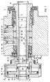
- FIG. 1 is an axial section view of this lathe doll
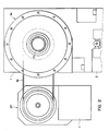
- FIG. 2 is a front elevation view in the direction of arrow A in FIG. 1.
- the drawing shows the doll frame 1 which is adjusted and fixed to the base 2 of a lathe, this lathe being designed so as to machine parts at the front end of a bar of material which passes through the doll and which is fixed and driven in rotation by the spindle, the essential elements of which will now be described.
- the frame 1 comprises a cylindrical passage 3 in which are mounted two double ball bearings 4 and 5 and outside these bearings auxiliary devices 6 and 7 for positioning and retaining oil.
- the bearings 4 and 5 are used to support a spindle body 8 whose construction is standardized and which comprises, in particular at its front end, bores 9 and 10 arranged so as to receive a clamping cone (not shown) cooperating with a clamp allowing attachment to the spindle body of the workpieces or of the front end of a work bar housed inside the spindle body 8.
- This clamp is connected, in a manner known per se, to a clamping sleeve 11 which is a tubular part passing through the internal bore of the spindle body 8 and fixed, by means of a threaded sleeve 12, to a piston 13 which is situated behind the frame 1.
- This piston 13 is engaged at the interior of a cylinder 14 consisting of a rear bottom 15, a front bottom 16 and a circular side wall 17, of a part with the bottom 15.
- This front bottom 16 is integral with a circular part 18 which forms a pulley and which is connected by a belt 19 to a motor, generally designated by 20, fixed on a console 21.
- the cylinder 14 extends overhang at the rear of the spindle body 8 to which it is fixed by screws 22, but, as will be seen, the length of the overhang and the value masses thus supported are kept at minimum values thanks to the special arrangement provided for the means for supplying the cylinder with compressed air.
- These means essentially comprise a distributor 23 which is a tubular part, with rectangular profile, fixed in the bore 3 by means of pivot screws 24 and 25. This part is centered relative to the bore 3, by a slight driving . Its internal bore is adjusted with a precision of a few micrometers.
- the distributor 23 comprises, in its external cylindrical face, two grooves 26 and 27 of rectangular profile, formed on the periphery of the external face, at a some distance from each other. In the bottom of each of these grooves 26 and 27 are provided radial passages 28 which terminate in the bottom of internal grooves 29 and 30, themselves formed in the internal bore of the part 23 at the same axial dimensions as the grooves 26 and 27.
- the grooves 26 and 27 are supplied, through the frame 1, by conduits 31 and 32 drilled in the frame 1 and the upper end of which is connected by means not shown to a reversing valve itself connected to a compressed air source and an exhaust opening.
- the groove 29 communicates with a conduit 33 formed from a series of bores made in the spindle body 8 and leading to an orifice 34 in the rear face of the spindle body 8.
- the groove 30 communicates with a conduit 35, also formed by a series of bores ending in the face 34 of the spindle body 8.
- two conduits 36 and 37 formed of series of bores, connected to the conduits 33 and 35 by seals and terminating one (33) in the rear bottom wall of the cylinder 14 and the other (35) in the front bottom wall of this cylinder.
- the air supply holes in the distributor 23 are strongly spaced from each other, so that one can tolerate a play between the distributor and the moving part relative to it. This results in the elimination of the risk of seizure without compromising operating safety due to an untimely pressure drop.
- the clearance is a few hundredths of a millimeter. This is in addition to the effects of mass reduction and reduction of the overhang and also contributes to better conditions for turning at high speeds and maintaining machining precision.
- the spindle body can be equipped with a standardized spindle nose allowing, by the adaptation of different sleeves, the use of many different clamping means without the need to change the spindle.
- the through passage formed inside the spindle body 8, allows work from a bar of material.
- the clamping cylinder 14 operates with a double effect: by pulling and pushing, which also promotes the use of numerous and varied clamping means.
- clamping means acting under the effect of a spring and in which the compressed air is only used to loosen the clamp can also be provided in a different embodiment from that shown in the drawing while using a fixed distributor usefully occupying the free space between the two bearings supporting the brooch.
Landscapes
- Engineering & Computer Science (AREA)
- Mechanical Engineering (AREA)
- General Engineering & Computer Science (AREA)
- Gripping On Spindles (AREA)
- Iron Core Of Rotating Electric Machines (AREA)
- Magnetic Bearings And Hydrostatic Bearings (AREA)
- Turning (AREA)
Abstract
Description
La présente invention se rapporte de manière générale à une broche de machine-outil comportant un bâti, un corps de broche tournant dans le bâti et un dispositif de serrage associé au corps de broche.The present invention relates generally to a machine tool spindle comprising a frame, a spindle body rotating in the frame and a clamping device associated with the spindle body.
On utilise des broches de ce genre soit comme poupée dans les tours, soit comme porte-outil lorsqu'il s'agit de supporter un outil tournant et de l'entraîner en rotation. Dans ce dernier cas, les broches peuvent se trouver associées à des machines-outils de différents types et notamment à des centres d'usinage complexe.Spindles of this kind are used either as a headstock in lathes or as a tool holder when it comes to supporting a rotating tool and driving it in rotation. In the latter case, the spindles can be associated with machine tools of different types and in particular with complex machining centers.
On constate actuellement, surtout dans le domaine du tournage, une tendance de plus en plus marquée à usiner avec des vitesses de coupe élevées. Ce mode de faire exige que les machines-outils soient équipées de broches aptes à supporter de hautes vitesses de rotation sans échauffement ni vibration, de façon à conserver une haute qualité de l'usinage. En même temps, on demande toujours plus d'universalité dans le travail des machines-outils et notamment des tours, ce qui suppose un équipement varié et facilement interchangeable. Les broches doivent donc comporter des moyens de fixation de type universel.Currently, especially in the turning sector, there is an increasingly marked tendency to machine with high cutting speeds. This mode of operation requires that machine tools be equipped with spindles capable of withstanding high rotational speeds without heating or vibration, so as to maintain a high quality of machining. At the same time, there is always a demand for more universality in the work of machine tools and in particular lathes, which requires varied and easily interchangeable equipment. The pins must therefore include universal type fixing means.
Dans les broches connues jusqu'à maintenant, la commande par air comprimé de l'ouverture et de la fermeture de la pince, supportant soit la pièce à usiner ou la barre de matériau, ou encore un outil, n'a pas été solutionnée de manière permettant d'atteindre facilement les vitesses maximales que l'on désire obtenir. En général, la pince proprement dite est fixée à l'extrémité d'une douille de serrage, appelée également tube de serrage, qui est mobile axialement dans le corps de broche. Cette douille est solidaire, à son extrémité arrière, d'un piston mobile dans un cylindre, qui tourne avec la broche, dans un boîtier d'alimentation en fluide. Toutefois, cet agencement et son raccordement à une source d'air comprimé sont cause, dans les machines connues, de vibrations qui entraînent elles-mêmes des échauffements et des défauts d'équilibrage inadmissibles.In the spindles known to date, the compressed air control of the opening and closing of the clamp, supporting either the workpiece or the material bar, or even a tool, has not been solved. way to easily reach the maximum speeds that one wishes to obtain. In general, the clamp itself is fixed to the end of a clamping sleeve, also called a clamping tube, which is axially movable in the spindle body. This socket is integral at its end rear, of a piston movable in a cylinder, which rotates with the spindle, in a fluid supply housing. However, this arrangement and its connection to a source of compressed air is the cause, in known machines, of vibrations which themselves cause overheating and unacceptable balancing faults.
On connaît déjà, par les documents US-3,020,057 (Gamet) et DE-33 25 880 (Leidenfrost) des dispositifs capables de commander au moyen d'un fluide sous pression des pistons se déplaçant dans des cylindres supportés par une broche tournant autour de son axe. Il s'agit toutefois d'une alimentation en huile sous pression et les constructions prévues comportent un organe de distribution qui est combiné à un palier et dont le diamètre excède celui du palier. Ces constructions ne sont pas conçues pour un fonctionnement à vitesse élevée, l'utilisation d'un liquide de commande interdisant de telles applications.Already known from documents US-3,020,057 (Gamet) and DE-33 25 880 (Leidenfrost) devices capable of controlling by means of a pressurized fluid pistons moving in cylinders supported by a spindle rotating around its axis. However, it is a supply of pressurized oil and the constructions provided include a distribution member which is combined with a bearing and whose diameter exceeds that of the bearing. These constructions are not designed for operation at high speed, the use of a control liquid prohibiting such applications.
La présente invention a pour objet une broche de machine-outil comportant un bâti, un corps de broche tournant dans le bâti sur deux paliers à roulement espacés axialement l'un de l'autre, et un dispositif de serrage associé au corps de broche, et comportant lui-même un piston mobile dans un cylindre et des moyens d'alimentation du cylindre en fluide de commande, les dits moyens d'alimentation comportant un distributeur placé entre les dits paliers dans le bâti, relié, d'une part, à des conduits fixes d'admission et d'evacuation percés dans le bâti et, d'autre part, à des conduits rotatifs correspondant aux conduits fixes et ménagés dans le corps de broche, ledit distributeur entourant coaxialement le corps de broche.The subject of the present invention is a machine tool spindle comprising a frame, a spindle body rotating in the frame on two rolling bearings spaced axially from each other, and a clamping device associated with the spindle body, and itself comprising a piston movable in a cylinder and means for supplying the cylinder with control fluid, said supply means comprising a distributor placed between said bearings in the frame, connected, on the one hand, to fixed inlet and outlet ducts drilled in the frame and, on the other hand, rotary ducts corresponding to the fixed ducts formed in the spindle body, said distributor coaxially surrounding the spindle body.
Une broche de ce genre est connue notamment par le document US-3 020 057 susmentionné.A spindle of this kind is known in particular from the document US-3,020,057 mentioned above.
L'invention vise à remédier aux inconvénients et aux défauts des dispositifs connus en créant une broche de machine-outil perfectionnée, dans laquelle des moyens de commande du piston par air comprimé constituent un ensemble compact, centré et équilibré par rapport à l'axe du corps de broche, permettant une réduction des masses en mouvement rotatif.The invention aims to remedy the drawbacks and defects of known devices by creating an improved machine tool spindle, in which means for controlling the piston by compressed air constitute a compact unit, centered and balanced with respect to the axis of the spindle body, allowing a reduction of the masses in rotary movement.
L'invention vise également à créer une construction permettant d'atteindre ces objectifs tout en étant adaptable aussi bien à des poupées de tour qu'à des broches porte-outils dans des centres d'usinage de construction variée.The invention also aims to create a construction making it possible to achieve these objectives while being adaptable both to lathe dolls and to tool-holder spindles in machining centers of varied construction.
Dans ce but, la broche de machine-outil selon l'invention est caractérisée en ce que le fluide de commande est de l'air comprimé et ledit distributeur consiste en une pièce unique fixée dans un alésage du bâti et ayant une surface extérieure cylindrique de même diamètre qu'une surface correspondante de la partie fixe de l'un des dits paliers.For this purpose, the machine tool spindle according to the invention is characterized in that the control fluid is compressed air and said distributor consists of a single piece fixed in a bore of the frame and having a cylindrical outer surface of same diameter as a corresponding surface of the fixed part of one of said bearings.
Du fait que les moyens d'alimentation ont pu être logés entre les paliers du corps de broche, l'équilibrage de la broche est possible d'une façon parfaite. En outre, la possibilité de faire passer les conduits d'alimentation et d'évacuation d'air comprimé à travers le corps de broche jusqu'à l'arrière de la poupée où ils se raccordent à un cylindre qui est placé en porte-à-faux derrière la poupée, tout en étant de courte longueur, donne une liberté considérable en ce qui concerne le dimensionnement et la disposition du cylindre et du piston de commande.Because the supply means could have been housed between the bearings of the spindle body, balancing of the spindle is perfectly possible. In addition, the possibility of passing the compressed air supply and exhaust ducts through the spindle body to the rear of the headstock where they are connected to a cylinder which is placed door-to-door. - false behind the headstock, while being short, gives considerable freedom with regard to the dimensioning and the arrangement of the cylinder and the control piston.
On va décrire ci-après, à titre d'exemple, pour montrer comment l'invention peut être réalisée, une forme d'exécution d'une poupée de tour construite selon l'invention.We will describe below, by way of example, to show how the invention can be implemented, an embodiment of a lathe doll constructed according to the invention.
Au dessin, la fig. 1 est une vue en coupe axiale de cette poupée de tour, et la fig. 2 une vue en élévation frontale dans le sens de la flèche A de la fig. 1.In the drawing, fig. 1 is an axial section view of this lathe doll, and FIG. 2 is a front elevation view in the direction of arrow A in FIG. 1.
On voit au dessin le bâti de poupée 1 qui est ajusté et fixé sur l'embase 2 d'un tour, ce tour étant conçu de manière à usiner des pièces à l'extrémité antérieure d'une barre de matériau qui traverse la poupée et qui est fixée et entraînée en rotation par la broche, dont on va décrire maintenant les éléments essentiels. Le bâti 1 comporte un passage cylindrique 3 dans lequel sont montés deux paliers à billes doubles 4 et 5 et à l'extérieur de ces paliers des dispositifs auxiliaires 6 et 7 de positionnement et de retenue d'huile. Les paliers 4 et 5 servent à supporter un corps de broche 8 dont la construction est standardisée et qui comporte, notamment à son extrémité avant, des alésages 9 et 10 agencés de façon à recevoir un cône de serrage (non représenté) coopérant avec une pince permettant la fixation au corps de broche des pièces à usiner ou de l'extrémité avant d'une barre à usiner logée à l'intérieur du corps de broche 8. Cette pince est reliée, de façon connue en soi, à une douille de serrage 11 qui est une pièce tubulaire traversant l'alésage interne du corps de broche 8 et fixée, par l'intermédiaire d'un manchon fileté 12, à un piston 13 qui est situé en arrière du bâti 1. Ce piston 13 est engagé à l'intérieur d'un cylindre 14 constitué d'un fond arrière 15, d'un fond avant 16 et d'une paroi latérale circulaire 17, d'une pièce avec le fond 15. Ce fond antérieur 16 est solidaire d'une partie circulaire 18 qui forme une poulie et qui est reliée par une courroie 19 à un moteur, désigné de façon générale par 20, fixé sur une console 21.The drawing shows the
Ainsi, le cylindre 14 s'étend en porte-à-faux à l'arrière du corps de broche 8 auquel il est fixé par des vis 22, mais, comme on le verra, la longueur du porte-à-faux et la valeur des masses ainsi supportées sont maintenues à des valeurs minimales grâce à la disposition particulière prévue pour les moyens d'alimentation du cylindre en air comprimé.Thus, the
Ces moyens comportent essentiellement un distributeur 23 qui est une pièce tubulaire, à profil rectangulaire, fixée dans l'alésage 3 par le moyen de vis à pivot 24 et 25. Cette pièce est centrée par rapport à l'alésage 3, par un léger chassage. Son alésage interne est ajusté avec une précision de quelques micromètres. Le distributeur 23 comporte, dans sa face cylindrique externe, deux gorges 26 et 27 de profil rectangulaire, ménagées sur le pourtour de la face externe, à une certaine distance l'une de l'autre. Dans le fond de chacune de ces gorges 26 et 27 sont ménagés des passages radiaux 28 qui aboutissent dans le fond de gorges internes 29 et 30, ménagées elles-mêmes dans l'alésage interne de la pièce 23 aux mêmes cotes axiales que les gorges 26 et 27.These means essentially comprise a
Les gorges 26 et 27 sont alimentées, à travers le bâti 1, par des conduits 31 et 32 percés dans le bâti 1 et dont l'extrémité supérieure est raccordée par des moyens non représentés à une vanne d'inversion reliée elle-même à une source d'air comprimé et à une ouverture d'évacuation.The
Comme on le voit à la fig. 1, la gorge 29 communique avec un conduit 33 formé d'une suite de perçages ménagés dans le corps de broche 8 et aboutissant à un orifice 34 dans la face arrière du corps de broche 8. De même, la gorge 30 communique avec un conduit 35, également formé d'une suite de perçages aboutissant dans la face 34 du corps de broche 8. Dans les parois du cylindre 14 sont également ménagés deux conduits 36 et 37, formés de suites de perçages, raccordés aux conduits 33 et 35 par des joints d'étanchéité et aboutissant l'un (33) dans la paroi de fond arrière du cylindre 14 et l'autre (35) dans la paroi de fond avant de ce cylindre.As seen in fig. 1, the
Ainsi, on a pu conduire les passages d'air comprimé à travers le corps de broche à l'intérieur de l'un des paliers de la poupée sans augmenter le diamètre du corps de broche, ce qui a permis de supprimer tout élément de distribution en porte-à-faux et de réduire la masse des corps en mouvement rotatif situés à l'extérieur du bâti.Thus, it was possible to conduct the compressed air passages through the spindle body inside one of the bearings of the headstock without increasing the diameter of the spindle body, which made it possible to remove any distribution element. cantilever and reduce the mass of bodies in rotary motion located outside the frame.
D'autre part, les trous d'amenée d'air dans le distributeur 23 sont fortement espacés l'un de l'autre, de sorte que l'on peut tolérer un jeu entre le distributeur et la pièce en mouvement relatif avec lui. Ceci a pour résultat la suppression des risques de grippage sans nuire à la sécurité du fonctionnement par suite de chute de pression intempestive. Le jeu est de quelques centièmes de millimètres. Cet élément s'ajoute aux effets de la diminution des masses et de la réduction du porte-à-faux et contribue également à de meilleures conditions pour tourner à des vitesses élevées et maintenir la précision d'usinage.On the other hand, the air supply holes in the
L'agencement décrit permet un montage rationnel des différents éléments de la construction. Une fois que la broche 8 a été engagée dans le palier antérieur 5 et verrouillée, le distributeur 23 est engagé dans l'alésage 3 et bloqué, puis le palier 4 est mis en place. Ainsi, l'espace axial entre les paliers est utilisé judicieusement.The arrangement described allows a rational assembly of the various elements of the construction. Once the
Ces particularités permettent à la broche décrite de répondre aux exigences actuelles de haute vitesse de rotation, de haute précision et d'universalité avec une construction simple et robuste ne reposant que sur deux paliers. La diminution importante du porte-à-faux et celle des masses en rotation notamment favorise un fonctionnement exempt de vibrations, créant ainsi des conditions de travail optimales pour l'obtention d'un état de surface de haute qualité. Le corps de broche peut être équipé d'un nez de broche normalisé permettant, par l'adaptation de différents manchons, l'utilisation de nombreux moyens de serrage différents sans nécessiter de changer la broche.These features allow the spindle described to meet the current requirements of high rotational speed, high precision and universality with a simple and robust construction based only on two bearings. The significant reduction in the overhang and that of the rotating masses in particular promotes vibration-free operation, thus creating optimal working conditions for obtaining a high quality surface finish. The spindle body can be equipped with a standardized spindle nose allowing, by the adaptation of different sleeves, the use of many different clamping means without the need to change the spindle.
D'autre part, le passage traversant, ménagé à l'intérieur du corps de broche 8, permet le travail à partir d'une barre de matériau.On the other hand, the through passage, formed inside the
Le cylindre de serrage 14 fonctionne à double effet : en tirant et en poussant, ce qui favorise également l'emploi de moyens de serrage nombreux et variés. Cependant, il est bien entendu que des moyens de serrage agissant sous l'effet d'un ressort et dans lesquels l'air comprimé n'est utilisé que pour desserrer la pince peuvent également être prévus dans une forme d'exécution différente de celle qui est représentée au dessin tout en utilisant un distributeur fixe occupant utilement l'espace libre entre les deux paliers supportant la broche.The clamping
Claims (7)
- Machine tool spindle comprising a frame (1), a spindle body (8) turning in the frame (1) on two rolling bearings (4, 5) spaced axially one from the other, and a work chucking fixture (11-14) associated with the spindle body, and itself comprising a piston (13) movable in a cylinder (14) and means (29, 30, 33, 35) of feeding the cylinder with actuating fluid, the said feed means comprising a distributor (23) placed between the said bearings (4, 5) in the frame (1), connected on the one hand to fixed admission and evacuation pipes (31, 32) pierced in the frame (1), and, on the other hand to rotary pipes (33, 35) corresponding to the fixed pipes and arranged in the spindle body (8), the said distributor (23) surrounding coaxially the spindle body, characterized in that the actuating fluid is compressed air and the said distributor (23) consists of a single piece fixed in a bore of the frame (1) and having a cylindrical exterior surface of the same diameter as a corresponding surface (3) of the fixed part of one of the said bearings (4).
- Spindle according to claim 1, characterized in that the distributor (23) has a cylindrical bore with two internal circular grooves (27, 30) <sic. (29, 30)> arranged in this bore, a cylindrical external surface provided with two external circular grooves (26, 27) and radial drillings (28) arranged between each of the external grooves and a corresponding internal groove.
- Spindle according to claim 1, characterized in that the cylinder (14) is fastened to a rear wall of the spindle body (8), the said rotary pipes (33, 35) of the spindle body being linked with the corresponding pipes (36, 37) arranged in the walls of the cylinder.
- Spindle according to claim 2, characterized in that the piston (13) is a ring piston and in that the walls of the cyclinder have two pipes (36, 37) one abutting one of the sides of the piston, the other the other side.
- Spindle according to claim 1, characterized in that the chucking means comprise a collet (11) accomodated in the spindle body (8) and fixed to the piston (13), in a manner to arrange a central passage crossing the whole spindle and permitting the latter to guide a bar of material to be machined.
- Spindle according to claim 1 or claim 4, characterized in that its frame constitutes the frame of the stockhead of a lathe.
- Spindle according to one of the claims 1 to 4, characterized in that the chucking device, associated with the spindle body, is arranged in a manner to hold a removable machine tool in a position coaxial to the spindle.
Priority Applications (1)
| Application Number | Priority Date | Filing Date | Title |
|---|---|---|---|
| AT89810759T ATE89499T1 (en) | 1988-10-06 | 1989-10-05 | MACHINE TOOL SPINDLE. |
Applications Claiming Priority (2)
| Application Number | Priority Date | Filing Date | Title |
|---|---|---|---|
| CH372188 | 1988-10-06 | ||
| CH3721/88 | 1988-10-06 |
Publications (2)
| Publication Number | Publication Date |
|---|---|
| EP0363328A1 EP0363328A1 (en) | 1990-04-11 |
| EP0363328B1 true EP0363328B1 (en) | 1993-05-19 |
Family
ID=4262073
Family Applications (1)
| Application Number | Title | Priority Date | Filing Date |
|---|---|---|---|
| EP89810759A Expired - Lifetime EP0363328B1 (en) | 1988-10-06 | 1989-10-05 | Machine tool spindle |
Country Status (3)
| Country | Link |
|---|---|
| EP (1) | EP0363328B1 (en) |
| AT (1) | ATE89499T1 (en) |
| DE (1) | DE68906633T2 (en) |
Families Citing this family (3)
| Publication number | Priority date | Publication date | Assignee | Title |
|---|---|---|---|---|
| JPH05116009A (en) * | 1991-10-30 | 1993-05-14 | Fujii Seimitsu Kogyo Kk | Work holding device for machining |
| DE4341167A1 (en) * | 1993-12-02 | 1995-06-08 | Karl Hiestand | Device for transferring a print medium |
| DE19525343C2 (en) * | 1995-07-12 | 2000-11-09 | Gat Gmbh | Device for transferring fluid between machine parts rotatable relative to one another |
Family Cites Families (3)
| Publication number | Priority date | Publication date | Assignee | Title |
|---|---|---|---|---|
| US2157892A (en) * | 1937-03-12 | 1939-05-09 | Gisholt Machine Co | Transmission and control |
| FR1230498A (en) * | 1959-02-12 | 1960-09-16 | Prec Ind | Machine tool spindle with incorporated hydraulic motor |
| DE3325880A1 (en) * | 1983-07-18 | 1985-01-31 | Reinhold Ing.(grad.) 8431 Postbauer-Heng Leidenfrost | Pressure transmission device |
-
1989
- 1989-10-05 AT AT89810759T patent/ATE89499T1/en not_active IP Right Cessation
- 1989-10-05 EP EP89810759A patent/EP0363328B1/en not_active Expired - Lifetime
- 1989-10-05 DE DE89810759T patent/DE68906633T2/en not_active Expired - Fee Related
Also Published As
| Publication number | Publication date |
|---|---|
| ATE89499T1 (en) | 1993-06-15 |
| DE68906633D1 (en) | 1993-06-24 |
| EP0363328A1 (en) | 1990-04-11 |
| DE68906633T2 (en) | 1993-10-28 |
Similar Documents
| Publication | Publication Date | Title |
|---|---|---|
| EP0213075B1 (en) | Clamping device for a work piece or a bar stock | |
| US8382405B2 (en) | Spindle device for machine tool | |
| FR2556254A1 (en) | TOOL HOLDER ASSEMBLY | |
| EP0806264B1 (en) | Machine tool with eccentric spindle | |
| EP0006806B1 (en) | Clamping device enabling a workpiece to be worked at both ends simultaneously | |
| FR2612438A1 (en) | MACHINE TOOL, IN PARTICULAR DRILL OR TAPPING MACHINE | |
| EP0363328B1 (en) | Machine tool spindle | |
| FR2468428A1 (en) | TOOL FIXING DEVICE, ESPECIALLY FOR A HAND DRILL | |
| EP0476083B1 (en) | Machining unit with rotary head carrying pivoting tools | |
| FR2857891A1 (en) | TOWER FOR PORTEES | |
| EP0436453A1 (en) | Tool-unit with sensing device | |
| EP1778428A1 (en) | Arbour for milling cutter | |
| EP1238737B1 (en) | Tapping unit | |
| FR2532572A1 (en) | HEAD HOLDER FOR MACHINE TOOL | |
| EP0121638A1 (en) | Barstock guiding device for a multispindle lathe | |
| WO2004043646A1 (en) | Spindle unit | |
| EP3307462B1 (en) | Lathe and guide bushing | |
| EP1509361B1 (en) | Multi-axis machining centre with a workpiece-bearing spindle | |
| FR2699444A1 (en) | Mandrel for machine tool | |
| FR2692510A1 (en) | Tool holder speed adaptor for fixed machine tool - is fastened to machine tool spindle with bearings and rotation preventer including pulley drive increasing speed to adaptor tool | |
| WO1990011159A1 (en) | Tool-holder and high-speed spindle | |
| FR2548566A1 (en) | Automatic spiral-type total travel chuck with built-in fluid motor | |
| FR2848888A1 (en) | Fixing device for support head of tool to machine tool spindle comprises collar fixed to spindle body made of radially deformable elastic material able to clamp cylindrical flange integral with body head | |
| FR2524360A1 (en) | UNIVERSAL MACHINE TOOL WITH A PLURALITY OF MACHINING POSTS, CONSTITUTING A MACHINING CENTER | |
| FR2688725A1 (en) | OVEN WITH MEANS FOR CLAMPING PARTS WITHOUT REVOLUTION SYMMETRY. |
Legal Events
| Date | Code | Title | Description |
|---|---|---|---|
| PUAI | Public reference made under article 153(3) epc to a published international application that has entered the european phase |
Free format text: ORIGINAL CODE: 0009012 |
|
| AK | Designated contracting states |
Kind code of ref document: A1 Designated state(s): AT CH DE FR GB IT LI NL SE |
|
| 17P | Request for examination filed |
Effective date: 19900706 |
|
| 17Q | First examination report despatched |
Effective date: 19910613 |
|
| GRAA | (expected) grant |
Free format text: ORIGINAL CODE: 0009210 |
|
| AK | Designated contracting states |
Kind code of ref document: B1 Designated state(s): AT CH DE FR GB IT LI NL SE |
|
| PG25 | Lapsed in a contracting state [announced via postgrant information from national office to epo] |
Ref country code: SE Effective date: 19930519 Ref country code: NL Effective date: 19930519 Ref country code: GB Effective date: 19930519 |
|
| REF | Corresponds to: |
Ref document number: 89499 Country of ref document: AT Date of ref document: 19930615 Kind code of ref document: T |
|
| REF | Corresponds to: |
Ref document number: 68906633 Country of ref document: DE Date of ref document: 19930624 |
|
| ITF | It: translation for a ep patent filed | ||
| NLV1 | Nl: lapsed or annulled due to failure to fulfill the requirements of art. 29p and 29m of the patents act | ||
| GBV | Gb: ep patent (uk) treated as always having been void in accordance with gb section 77(7)/1977 [no translation filed] |
Effective date: 19930519 |
|
| PLBE | No opposition filed within time limit |
Free format text: ORIGINAL CODE: 0009261 |
|
| STAA | Information on the status of an ep patent application or granted ep patent |
Free format text: STATUS: NO OPPOSITION FILED WITHIN TIME LIMIT |
|
| 26N | No opposition filed | ||
| PGFP | Annual fee paid to national office [announced via postgrant information from national office to epo] |
Ref country code: AT Payment date: 19961030 Year of fee payment: 8 |
|
| PGFP | Annual fee paid to national office [announced via postgrant information from national office to epo] |
Ref country code: CH Payment date: 19961104 Year of fee payment: 8 |
|
| PGFP | Annual fee paid to national office [announced via postgrant information from national office to epo] |
Ref country code: FR Payment date: 19961108 Year of fee payment: 8 |
|
| PGFP | Annual fee paid to national office [announced via postgrant information from national office to epo] |
Ref country code: DE Payment date: 19961125 Year of fee payment: 8 |
|
| PG25 | Lapsed in a contracting state [announced via postgrant information from national office to epo] |
Ref country code: AT Free format text: LAPSE BECAUSE OF NON-PAYMENT OF DUE FEES Effective date: 19971005 |
|
| PG25 | Lapsed in a contracting state [announced via postgrant information from national office to epo] |
Ref country code: LI Free format text: LAPSE BECAUSE OF NON-PAYMENT OF DUE FEES Effective date: 19971031 Ref country code: FR Free format text: THE PATENT HAS BEEN ANNULLED BY A DECISION OF A NATIONAL AUTHORITY Effective date: 19971031 Ref country code: CH Free format text: LAPSE BECAUSE OF NON-PAYMENT OF DUE FEES Effective date: 19971031 |
|
| REG | Reference to a national code |
Ref country code: CH Ref legal event code: PL |
|
| PG25 | Lapsed in a contracting state [announced via postgrant information from national office to epo] |
Ref country code: DE Free format text: LAPSE BECAUSE OF NON-PAYMENT OF DUE FEES Effective date: 19980701 |
|
| REG | Reference to a national code |
Ref country code: FR Ref legal event code: ST |
|
| PG25 | Lapsed in a contracting state [announced via postgrant information from national office to epo] |
Ref country code: IT Free format text: LAPSE BECAUSE OF NON-PAYMENT OF DUE FEES;WARNING: LAPSES OF ITALIAN PATENTS WITH EFFECTIVE DATE BEFORE 2007 MAY HAVE OCCURRED AT ANY TIME BEFORE 2007. THE CORRECT EFFECTIVE DATE MAY BE DIFFERENT FROM THE ONE RECORDED. Effective date: 20051005 |