EP0363243A1 - Verfahren und Vorrichtung zur autonomen Steuerung einer geostationären satellitenumlaufbahn - Google Patents
Verfahren und Vorrichtung zur autonomen Steuerung einer geostationären satellitenumlaufbahn Download PDFInfo
- Publication number
- EP0363243A1 EP0363243A1 EP89402567A EP89402567A EP0363243A1 EP 0363243 A1 EP0363243 A1 EP 0363243A1 EP 89402567 A EP89402567 A EP 89402567A EP 89402567 A EP89402567 A EP 89402567A EP 0363243 A1 EP0363243 A1 EP 0363243A1
- Authority
- EP
- European Patent Office
- Prior art keywords
- satellite
- vector
- delay
- detectors
- measurements
- Prior art date
- Legal status (The legal status is an assumption and is not a legal conclusion. Google has not performed a legal analysis and makes no representation as to the accuracy of the status listed.)
- Granted
Links
- 238000000034 method Methods 0.000 title claims abstract description 9
- 239000013598 vector Substances 0.000 claims abstract description 39
- 238000005259 measurement Methods 0.000 claims abstract description 35
- 239000011159 matrix material Substances 0.000 claims abstract description 16
- 230000035945 sensitivity Effects 0.000 claims abstract description 6
- 238000004364 calculation method Methods 0.000 claims description 23
- 235000019892 Stellar Nutrition 0.000 claims description 9
- 238000012423 maintenance Methods 0.000 claims description 4
- 238000001914 filtration Methods 0.000 description 4
- 230000005855 radiation Effects 0.000 description 3
- 238000004088 simulation Methods 0.000 description 3
- PEDCQBHIVMGVHV-UHFFFAOYSA-N Glycerine Chemical compound OCC(O)CO PEDCQBHIVMGVHV-UHFFFAOYSA-N 0.000 description 1
- 230000001174 ascending effect Effects 0.000 description 1
- 238000010276 construction Methods 0.000 description 1
- 230000003247 decreasing effect Effects 0.000 description 1
- 230000001934 delay Effects 0.000 description 1
- 238000010586 diagram Methods 0.000 description 1
- 230000000694 effects Effects 0.000 description 1
- 230000006870 function Effects 0.000 description 1
- 230000005484 gravity Effects 0.000 description 1
- 230000001939 inductive effect Effects 0.000 description 1
- 230000014759 maintenance of location Effects 0.000 description 1
- 230000003287 optical effect Effects 0.000 description 1
- 230000007704 transition Effects 0.000 description 1
- 230000017105 transposition Effects 0.000 description 1
Images

Classifications
-
- G—PHYSICS
- G01—MEASURING; TESTING
- G01C—MEASURING DISTANCES, LEVELS OR BEARINGS; SURVEYING; NAVIGATION; GYROSCOPIC INSTRUMENTS; PHOTOGRAMMETRY OR VIDEOGRAMMETRY
- G01C21/00—Navigation; Navigational instruments not provided for in groups G01C1/00 - G01C19/00
- G01C21/24—Navigation; Navigational instruments not provided for in groups G01C1/00 - G01C19/00 specially adapted for cosmonautical navigation
-
- B—PERFORMING OPERATIONS; TRANSPORTING
- B64—AIRCRAFT; AVIATION; COSMONAUTICS
- B64G—COSMONAUTICS; VEHICLES OR EQUIPMENT THEREFOR
- B64G1/00—Cosmonautic vehicles
- B64G1/22—Parts of, or equipment specially adapted for fitting in or to, cosmonautic vehicles
- B64G1/24—Guiding or controlling apparatus, e.g. for attitude control
- B64G1/244—Spacecraft control systems
- B64G1/245—Attitude control algorithms for spacecraft attitude control
-
- B—PERFORMING OPERATIONS; TRANSPORTING
- B64—AIRCRAFT; AVIATION; COSMONAUTICS
- B64G—COSMONAUTICS; VEHICLES OR EQUIPMENT THEREFOR
- B64G1/00—Cosmonautic vehicles
- B64G1/22—Parts of, or equipment specially adapted for fitting in or to, cosmonautic vehicles
- B64G1/24—Guiding or controlling apparatus, e.g. for attitude control
- B64G1/36—Guiding or controlling apparatus, e.g. for attitude control using sensors, e.g. sun-sensors, horizon sensors
-
- B—PERFORMING OPERATIONS; TRANSPORTING
- B64—AIRCRAFT; AVIATION; COSMONAUTICS
- B64G—COSMONAUTICS; VEHICLES OR EQUIPMENT THEREFOR
- B64G1/00—Cosmonautic vehicles
- B64G1/22—Parts of, or equipment specially adapted for fitting in or to, cosmonautic vehicles
- B64G1/24—Guiding or controlling apparatus, e.g. for attitude control
- B64G1/26—Guiding or controlling apparatus, e.g. for attitude control using jets
-
- B—PERFORMING OPERATIONS; TRANSPORTING
- B64—AIRCRAFT; AVIATION; COSMONAUTICS
- B64G—COSMONAUTICS; VEHICLES OR EQUIPMENT THEREFOR
- B64G1/00—Cosmonautic vehicles
- B64G1/22—Parts of, or equipment specially adapted for fitting in or to, cosmonautic vehicles
- B64G1/24—Guiding or controlling apparatus, e.g. for attitude control
- B64G1/36—Guiding or controlling apparatus, e.g. for attitude control using sensors, e.g. sun-sensors, horizon sensors
- B64G1/361—Guiding or controlling apparatus, e.g. for attitude control using sensors, e.g. sun-sensors, horizon sensors using star sensors
-
- B—PERFORMING OPERATIONS; TRANSPORTING
- B64—AIRCRAFT; AVIATION; COSMONAUTICS
- B64G—COSMONAUTICS; VEHICLES OR EQUIPMENT THEREFOR
- B64G1/00—Cosmonautic vehicles
- B64G1/22—Parts of, or equipment specially adapted for fitting in or to, cosmonautic vehicles
- B64G1/24—Guiding or controlling apparatus, e.g. for attitude control
- B64G1/36—Guiding or controlling apparatus, e.g. for attitude control using sensors, e.g. sun-sensors, horizon sensors
- B64G1/363—Guiding or controlling apparatus, e.g. for attitude control using sensors, e.g. sun-sensors, horizon sensors using sun sensors
-
- B—PERFORMING OPERATIONS; TRANSPORTING
- B64—AIRCRAFT; AVIATION; COSMONAUTICS
- B64G—COSMONAUTICS; VEHICLES OR EQUIPMENT THEREFOR
- B64G1/00—Cosmonautic vehicles
- B64G1/22—Parts of, or equipment specially adapted for fitting in or to, cosmonautic vehicles
- B64G1/24—Guiding or controlling apparatus, e.g. for attitude control
- B64G1/36—Guiding or controlling apparatus, e.g. for attitude control using sensors, e.g. sun-sensors, horizon sensors
- B64G1/365—Guiding or controlling apparatus, e.g. for attitude control using sensors, e.g. sun-sensors, horizon sensors using horizon or Earth sensors
Definitions
- the invention relates to the orbit control of space vehicles such as satellites and is more particularly aimed at the case of space vehicles in geostationary orbit (in this case, we commonly speak of "station keeping”, as a synonym of "control of 'geostationary orbit').
- ⁇ is the right ascent of the ascending node (this designates the orientation of the line of nodes relative to any predetermined inertial coordinate system); - the average longitude l m .
- Maintaining a position therefore currently requires ground infrastructure, with permanent staff mobilization (24 hours a day, 365 days a year), which results in significant operating costs for the satellite.
- the object of the invention is to make it possible to calculate, on board the satellite and autonomously, the orbit parameters and the station maintenance maneuvers to be carried out, so as to be able to do without permanent ground assistance, and no longer involve such a ground control center only occasionally.
- Z is a measurement vector whose components are deduced from the angles ⁇ 1 and ⁇ 2 .
- H is a measurement matrix.
- B is a bias vector determined beforehand by comparison between the measured vector Z and measurements made on the ground, consequently, station maintenance maneuvers are applied by nozzles.
- angles ⁇ 1 and ⁇ 2 are determined from measurements made by at least one terrestrial detector, a plurality of solar detectors and a stellar detector oriented towards the North along the South-North axis of the satellite, the measurements of these detectors being filtered separately so as to obtain for these measurements a global delay (intrinsic delay of the detector + filtering delay) identical.
- the invention also provides a station retention system comprising: at least one terrestrial detector fitted with a filter adapted to generate a delay such that the overall delay (own delay of the detector + delay of the filter) has a predetermined value, a plurality of solar detectors fitted with a filter adapted to generate a delay such that the overall delay is equal to said predetermined value, at least one star detector oriented towards the North along the South-North axis of the satellite fitted with a filter adapted to generate a delay such that the overall delay is equal to said predetermined value, - a position calculation element connected to these filters and adapted to deduce from the filtered measurements of said detectors the angle ⁇ 1 between the directions (Satellite-Sun) and (Satellite-Earth) and the angle ⁇ 2 between the directions (Satellite-Star Polar) and (Satellite-Earth), an orbital parameter calculation element connected to the output of the position calculation element and adapted to determine the state vector E of the satellite, composed of the orbital parameters, according to the formula: Z
- an attitude determination unit is connected to the outputs of the terrestrial, solar and stellar detectors and to the output of the element for calculating orbital parameters.
- the element for calculating orbital parameters is a KALMAN filter.
- the auxiliary element for bias calculation is a FRIEDLAND filter.
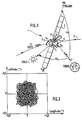
- FIG. 1 schematically represents a satellite 1 describing an orbit 2 around the Earth.
- satellite 1 is associated with a reference frame XYZ whose axis X is tangent to orbit 2, and oriented in the direction in which the orbit is traversed (from West to East), and the Z axis is directed towards the Earth (geocentric axis).
- the satellite comprises a platform carrying solar panels 3, reflectors 4 and propulsion nozzles of any suitable known type.
- the platform of this satellite comprises at least one terrestrial sensor oriented towards the Earth and shown diagrammatically in T1 as well as a plurality of solar detectors distributed in a plane parallel to the plane of the axes X and Z and adapted to be successively facing the Sun as the satellite describes its orbit.
- Different configurations are known; by way of example, there are three solar detectors here: S1, S2, S3, arranged one S2 on the face facing the Earth and the other two, S1 and S3, on the edges opposite to this face .
- the platform of this satellite is also provided, here on its north face (opposite the Y axis) with a star detector P, of any suitable known type, oriented towards the north, along the South-North axis.
- a star detector P of any suitable known type, oriented towards the north, along the South-North axis. This is for example a detector chosen from the SODERN or GALILEO range.
- the solar detectors S1 to S3, terrestrial T1 and stellar P are classified in decreasing order respectively from the point of view of incident radiation power.
- detectors are sensitive to different ranges of radiation: terrestrial detectors are sensitive to infrared radiation from the Earth, solar detectors are formed from photoelectric cells and stellar detectors are based on bars or networks. CCD (in English “Charge Coupled Device”).
- these detectors conventionally include integrated filters inducing different delays.
- the invention uses the peculiarity that the Polar Star is of being the only star of its magnitude to be always in the field of vision of a stellar detector mounted on the North face of a satellite, and therefore its recognition n 'requires no sophisticated software.
- the terrestrial T1, solar S1 to S3 and stellar P detectors allow the angular orientation of the Earth, the Sun and the Polar Star to be noted at any time, respectively, in the reference frame linked to the satellite.
- Figure 2 illustrates the structure of the autonomous geostationary orbit control system.
- a filtering and synchronization device whose outputs are connected to a position calculation element 13 followed by a calculation element of orbital parameters 14 with which an auxiliary calibration element 15 is associated, also connected to the position calculation element 13 and connected to a telemetry unit 16 in connection with the ground.
- the output of the orbital parameters calculation element is connected to a calculation and control unit 17 under the control of which the stationary nozzles 18 are placed.
- An attitude determination unit 19 is connected at the same time to the unfiltered outputs of the detectors T1, S1 to S3 and P and to the output of the element for calculating the orbital parameters 14.
- a memory 20 is associated with the calculating element 14 for storing the orbital parameters calculated by this item 14.
- calculation elements 13, 14, 15, 17, 18 can be integrated into the on-board computer of the satellite.
- the invention firstly proposes, in 10, 11 and 12, to filter the raw measurements of the various detectors differently so as not only to obtain a appropriate predetermined residual noise level, but also to add a delay, different from one detector to another, such as the overall delay associated with each detector (or group of detectors of the same kind), i.e. the sum of the delay specific to each detector and the additional delay induced by the associated filter 10, 11 or 12, ie the same for all the measurements.
- a delay different from one detector to another, such as the overall delay associated with each detector (or group of detectors of the same kind), i.e. the sum of the delay specific to each detector and the additional delay induced by the associated filter 10, 11 or 12, ie the same for all the measurements.
- the overall delay is for example chosen to be 10 seconds.
- Z be a measurement vector formed from the navigation angles ⁇ 1 and ⁇ 2.
- the determination of the components of the measurement matrix H is within the competence of a person skilled in the art taking into account the definitions chosen for the vectors Z and E.
- the parameters X z , Y z and Y p of the matrix C correspond to the coordinates of these same unit vectors if, by changing the abovementioned notation, we write these coordinates (X z , Y z , Z z ) for the Sun and (X p , Y p , Z p ) for Polar.
- bias vector B The purpose of the bias vector B is to account for the internal errors and the alignment errors of the detectors.
- the procedure for calibrating these biases is as follows: the ground regularly determines (for example after putting into orbit then every year) the position of the satellite and its orbital parameters then downloads to the latter, thanks to the telemetry unit 16, these orbit parameters and / or the associated navigation angles.
- the parameters are then processed, as is the value Z deduced from the measurements of the detectors, by the auxiliary calculation element 15 which deduces therefrom the new value of the bias vector B.
- the bias vector once estimated at the end of a period of ten days is stored in this element 15 until the next calibration.
- the calculation function of this element 15 can then be deactivated so as not to unnecessarily stress the on-board computer.
- the calculation element 14 is in fact an orbit estimator filter; it is for example a KALMAN filter, the equations of which are well known to those skilled in the art.
- the auxiliary calculation element 15 is in practice a filter, for example of the FRIEDLAND type, the equations of which are also known. They make it possible to evaluate B from several measurements.
- the raw measurements of the detectors can be used to, thanks to element 18, determine the three attitude angles of the satellite (roll, yaw, pitch) from knowledge orbital parameters provided by element 14, therefore independently (the time constants of the filters integrated into the detectors are commonly around a few tenths of a second for the solar detectors, 0.5 second for the terrestrial detector, and 0 , 1 to 0.5 seconds for the star detector).
- the system of FIG. 2 therefore constitutes a completely autonomous system for determining both the orbit and the attitude.
Applications Claiming Priority (2)
| Application Number | Priority Date | Filing Date | Title |
|---|---|---|---|
| FR888813121A FR2637564B1 (fr) | 1988-10-06 | 1988-10-06 | Procede et systeme de controle autonome d'orbite d'un satellite geostationnaire |
| FR8813121 | 1988-10-06 |
Publications (2)
| Publication Number | Publication Date |
|---|---|
| EP0363243A1 true EP0363243A1 (de) | 1990-04-11 |
| EP0363243B1 EP0363243B1 (de) | 1993-12-29 |
Family
ID=9370753
Family Applications (1)
| Application Number | Title | Priority Date | Filing Date |
|---|---|---|---|
| EP89402567A Expired - Lifetime EP0363243B1 (de) | 1988-10-06 | 1989-09-19 | Verfahren und Vorrichtung zur autonomen Steuerung einer geostationären satellitenumlaufbahn |
Country Status (7)
| Country | Link |
|---|---|
| US (1) | US5108050A (de) |
| EP (1) | EP0363243B1 (de) |
| JP (1) | JP2847302B2 (de) |
| CA (1) | CA2000214C (de) |
| DE (1) | DE68911830T2 (de) |
| ES (1) | ES2047695T3 (de) |
| FR (1) | FR2637564B1 (de) |
Cited By (6)
| Publication number | Priority date | Publication date | Assignee | Title |
|---|---|---|---|---|
| FR2661261A1 (fr) * | 1990-04-19 | 1991-10-25 | Gen Electric | Commande d'attitude tridimensionnelle d'un engin spatial utilisant un detecteur d'etoile polaire. |
| FR2670746A1 (fr) * | 1990-12-21 | 1992-06-26 | Aerospatiale | Systeme de controle d'attitude pour satellite 3-axes,; notamment pour satellite d'observation. |
| FR2670886A1 (fr) * | 1990-12-21 | 1992-06-26 | Aerospatiale | Procede de reacquisition d'attitude par reconnaissance d'etoile pour satellite stabilise 3-axes. |
| EP0496879A1 (de) * | 1990-08-22 | 1992-08-05 | Microcosm Inc | Vorrichtung zum halten eines satelliten auf seiner umlaufbahn. |
| DE4129630A1 (de) * | 1991-09-06 | 1993-05-06 | Deutsche Aerospace Ag, 8000 Muenchen, De | Messanordnung und regelungssystem zur lageregelung eines dreiachsenstabilisierten satelliten sowie zugehoerige mess- und regelverfahren |
| EP0748737A1 (de) * | 1995-05-24 | 1996-12-18 | Daimler-Benz Aerospace Aktiengesellschaft | Dreiachsenstabilisierter, erdorientierter Satellit und zugehöriges Sonnen- und Erdakquisitionsverfahren |
Families Citing this family (20)
| Publication number | Priority date | Publication date | Assignee | Title |
|---|---|---|---|---|
| DE19703629A1 (de) * | 1997-01-31 | 1998-08-06 | Daimler Benz Aerospace Ag | Verfahren zur bordautonomen Bestimmung der Position eines Satelliten |
| FR2697651B1 (fr) * | 1992-10-29 | 1995-02-03 | Aerospatiale | Procédé et appareil de calibration des gyromètres d'un satellite stabilisé 3-axes. |
| US5562266A (en) * | 1992-10-29 | 1996-10-08 | Aerospatiale Societe Nationale Industrielle | Rate gyro calibration method and apparatus for a three-axis stabilized satellite |
| US5452869A (en) * | 1992-12-18 | 1995-09-26 | Hughes Aircraft Company | On-board three-axes attitude determination and control system |
| RU2033949C1 (ru) * | 1993-02-09 | 1995-04-30 | Севастиян Дмитриевич Гнатюк | Автономная бортовая система управления космического аппарата "гасад" |
| US5452077A (en) * | 1993-12-09 | 1995-09-19 | Hughes Aircraft Company | Transient-free method of determining satellite attitude |
| US6098929A (en) * | 1998-01-28 | 2000-08-08 | Falbel; Gerald | Three axis attitude readout system for geosynchronous spacecraft |
| US6145790A (en) * | 1998-09-22 | 2000-11-14 | Hughes Electronics Corporation | Attitude determination system and method |
| DE60032681T2 (de) * | 1999-08-13 | 2007-10-18 | Hughes Electronics Corp., El Segundo | Umlaufbahnsteuerung eines Raumfahrzeuges bei Rückmeldung der Lage der Umlaufbahn |
| US6691033B1 (en) * | 2000-07-26 | 2004-02-10 | Hughes Electronics Corporation | System and method for calibrating inter-star-tracker misalignments in a stellar inertial attitude determination system |
| US7454272B1 (en) * | 2005-08-25 | 2008-11-18 | Raytheon Company | Geostationary stationkeeping method |
| US8174433B1 (en) | 2009-02-26 | 2012-05-08 | Raytheon Company | Bias estimation and orbit determination |
| US9091552B2 (en) * | 2011-10-25 | 2015-07-28 | The Boeing Company | Combined location and attitude determination system and methods |
| FR2983981B1 (fr) * | 2011-12-09 | 2014-08-22 | Thales Sa | Procede et systeme de commande d'un ensemble d'au moins deux satellites, concus pour fournir un service sur une orbite geostationnaire, rendant ledit service sur une orbite non-geostationnaire |
| US9073648B2 (en) * | 2013-02-15 | 2015-07-07 | The Boeing Company | Star tracker rate estimation with kalman filter enhancement |
| CN111238567A (zh) * | 2020-01-06 | 2020-06-05 | 航天恒星科技有限公司 | 一种卫星在轨健康监控装置 |
| CN112052560A (zh) * | 2020-07-30 | 2020-12-08 | 上海航天控制技术研究所 | 一种系统级星载计算机维护模式闭环仿真设计方法 |
| CN112319850B (zh) * | 2020-09-30 | 2022-05-24 | 中国卫通集团股份有限公司 | 一种自动实现同步轨道卫星位置保持的方法及装置 |
| CN112526561B (zh) * | 2020-11-27 | 2024-04-23 | 中国科学院国家天文台 | 延长地球静止轨道通信卫星两行星历预报时段方法 |
| CN112769466B (zh) * | 2020-12-22 | 2022-08-12 | 火眼位置数智科技服务有限公司 | 低轨卫星星座构型保持方法 |
Citations (5)
| Publication number | Priority date | Publication date | Assignee | Title |
|---|---|---|---|---|
| DE3417661A1 (de) * | 1983-05-13 | 1984-11-15 | Mitsubishi Denki K.K., Tokio/Tokyo | System zur regelung der lage eines kuenstlichen satelliten |
| EP0174715A2 (de) * | 1984-09-13 | 1986-03-19 | Mitsubishi Denki Kabushiki Kaisha | Neigungswinkelrechner für einen geostationären Satelliten |
| EP0209429A1 (de) * | 1985-06-20 | 1987-01-21 | Matra | Vorrichtung und Verfahren zum Einbringen eines Satelliten auf einer geostationären Bahn mit Stabilisierung in den drei Raumachsen |
| EP0251808A2 (de) * | 1986-07-04 | 1988-01-07 | The Marconi Company Limited | Satelliten-Lageregelung |
| EP0267086A1 (de) * | 1986-10-16 | 1988-05-11 | Centre National D'etudes Spatiales | Raumfahrzeug mit Ausrichtanordnung einer Antenne zur Erde |
Family Cites Families (2)
| Publication number | Priority date | Publication date | Assignee | Title |
|---|---|---|---|---|
| US4617634A (en) * | 1983-06-28 | 1986-10-14 | Mitsubishi Denki Kabushiki Kaisha | Artificial satellite attitude control system |
| GB8809247D0 (en) * | 1988-04-20 | 1988-05-25 | British Aerospace | Attitude recovery for spacecraft |
-
1988
- 1988-10-06 FR FR888813121A patent/FR2637564B1/fr not_active Expired - Fee Related
-
1989
- 1989-09-19 ES ES89402567T patent/ES2047695T3/es not_active Expired - Lifetime
- 1989-09-19 EP EP89402567A patent/EP0363243B1/de not_active Expired - Lifetime
- 1989-09-19 DE DE89402567T patent/DE68911830T2/de not_active Expired - Lifetime
- 1989-10-03 US US07/416,694 patent/US5108050A/en not_active Expired - Fee Related
- 1989-10-05 CA CA002000214A patent/CA2000214C/en not_active Expired - Fee Related
- 1989-10-05 JP JP1261230A patent/JP2847302B2/ja not_active Expired - Lifetime
Patent Citations (5)
| Publication number | Priority date | Publication date | Assignee | Title |
|---|---|---|---|---|
| DE3417661A1 (de) * | 1983-05-13 | 1984-11-15 | Mitsubishi Denki K.K., Tokio/Tokyo | System zur regelung der lage eines kuenstlichen satelliten |
| EP0174715A2 (de) * | 1984-09-13 | 1986-03-19 | Mitsubishi Denki Kabushiki Kaisha | Neigungswinkelrechner für einen geostationären Satelliten |
| EP0209429A1 (de) * | 1985-06-20 | 1987-01-21 | Matra | Vorrichtung und Verfahren zum Einbringen eines Satelliten auf einer geostationären Bahn mit Stabilisierung in den drei Raumachsen |
| EP0251808A2 (de) * | 1986-07-04 | 1988-01-07 | The Marconi Company Limited | Satelliten-Lageregelung |
| EP0267086A1 (de) * | 1986-10-16 | 1988-05-11 | Centre National D'etudes Spatiales | Raumfahrzeug mit Ausrichtanordnung einer Antenne zur Erde |
Cited By (11)
| Publication number | Priority date | Publication date | Assignee | Title |
|---|---|---|---|---|
| FR2661261A1 (fr) * | 1990-04-19 | 1991-10-25 | Gen Electric | Commande d'attitude tridimensionnelle d'un engin spatial utilisant un detecteur d'etoile polaire. |
| EP0496879A1 (de) * | 1990-08-22 | 1992-08-05 | Microcosm Inc | Vorrichtung zum halten eines satelliten auf seiner umlaufbahn. |
| EP0496879A4 (en) * | 1990-08-22 | 1992-08-12 | Microcosm, Inc. | Satellite orbit maintenance system |
| US5277385A (en) * | 1990-12-12 | 1994-01-11 | Aerospatiale Societe Nationale Industrielle | Method of attitude reacquisition for three-axis stabilized satellites using star recognition |
| FR2670746A1 (fr) * | 1990-12-21 | 1992-06-26 | Aerospatiale | Systeme de controle d'attitude pour satellite 3-axes,; notamment pour satellite d'observation. |
| FR2670886A1 (fr) * | 1990-12-21 | 1992-06-26 | Aerospatiale | Procede de reacquisition d'attitude par reconnaissance d'etoile pour satellite stabilise 3-axes. |
| EP0493143A1 (de) * | 1990-12-21 | 1992-07-01 | AEROSPATIALE Société Nationale Industrielle | System zur Lagestabilisierung eines dreiachs-stabilisierten Satelliten, insbesondere eines Beobachtungssatelliten |
| EP0493228A1 (de) * | 1990-12-21 | 1992-07-01 | AEROSPATIALE Société Nationale Industrielle | Verfahren zur Wiederlangung der Lage eines dreiachs-stabilisierten Satelliten mittels Sternidentifizierung |
| US5279483A (en) * | 1990-12-21 | 1994-01-18 | Aerospatiale Societe Nationale Industrielle | Attitude control system for a three-axis stabilized satellite especially a remote sensing satellite |
| DE4129630A1 (de) * | 1991-09-06 | 1993-05-06 | Deutsche Aerospace Ag, 8000 Muenchen, De | Messanordnung und regelungssystem zur lageregelung eines dreiachsenstabilisierten satelliten sowie zugehoerige mess- und regelverfahren |
| EP0748737A1 (de) * | 1995-05-24 | 1996-12-18 | Daimler-Benz Aerospace Aktiengesellschaft | Dreiachsenstabilisierter, erdorientierter Satellit und zugehöriges Sonnen- und Erdakquisitionsverfahren |
Also Published As
| Publication number | Publication date |
|---|---|
| ES2047695T3 (es) | 1994-03-01 |
| JPH02156312A (ja) | 1990-06-15 |
| CA2000214C (en) | 1993-12-21 |
| DE68911830D1 (de) | 1994-02-10 |
| FR2637564B1 (fr) | 1994-10-14 |
| DE68911830T2 (de) | 1994-04-28 |
| FR2637564A1 (fr) | 1990-04-13 |
| CA2000214A1 (en) | 1990-04-06 |
| EP0363243B1 (de) | 1993-12-29 |
| US5108050A (en) | 1992-04-28 |
| JP2847302B2 (ja) | 1999-01-20 |
Similar Documents
| Publication | Publication Date | Title |
|---|---|---|
| EP0363243B1 (de) | Verfahren und Vorrichtung zur autonomen Steuerung einer geostationären satellitenumlaufbahn | |
| EP0363244B1 (de) | Verfahren zur aktiven Steuerung nach drei Achsen einer geostationären Satelliteneinstellung | |
| EP0435708B1 (de) | Verfahren zur Steuerung der Neigung eines Satelliten bezüglich der Roll- und der Gierachse | |
| EP0571239B1 (de) | Verfahren und Vorrichtung zur Erdgewinnung mit Hilfe des Polarsterns für einen Dreiachs-stabilisierten Satelliten | |
| EP2181923B1 (de) | Entsättigungsverfahren und -system für die Trägheitsräder eines Raumschiffs | |
| EP0076179B1 (de) | Verfahren zur Ausrichtung der Rollachse eines Satelliten mit einer gewünschten Richtung | |
| FR2705448A1 (fr) | Système et procédé de détermination d'attitude d'un engin spatial utilisant des capteurs stellaires ou terrestres. | |
| EP0603058B1 (de) | Lagesteuerungsverfahren für zu einem Himmelsobjekt- ausgerichteten Satelliten und Satellit zur Durchführung desselben | |
| EP0199648B1 (de) | Verfahren und Vorrichtung zur Nutationsdämpfung eines Satelliten durch Steuerung der Gewichtslagebestimmung | |
| EP0493228B1 (de) | Verfahren zur Wiederlangung der Lage eines dreiachs-stabilisierten Satelliten mittels Sternidentifizierung | |
| EP3201091B1 (de) | Verfahren zur überwachung der lage eines satelliten in überlebensmodus, angepasste satellit und verfahren zur fernsteuerung solch eines satelliten | |
| EP0209429B1 (de) | Vorrichtung und Verfahren zum Einbringen eines Satelliten auf einer geostationären Bahn mit Stabilisierung in den drei Raumachsen | |
| EP3921235B1 (de) | Verfahren zur lageregelung eines satelliten im überlebensmodus ohne a-priori-kenntnis der lokalen umlaufzeit des satelliten | |
| CA1267949A (fr) | Procedure de repointage rapide des satellites a pointage terrestre, et notamment des satellites geostationnaires de telecommunication a stabilisation par volant d'inertie | |
| EP0341130B1 (de) | Verfahren zur Ausrichtung des Rollträgheitsmomentes eines drehenden Körpers im Raum zu einer gegebenen Richtung | |
| EP0678732B1 (de) | Verfahren und Vorrichtung zum Kalibrieren der Kreiseln eines dreiachsenstabilisierten Satelliten | |
| EP1635485B1 (de) | Optisches Übertragungsverfahren zwischen einem Terminal an Bord eines Raumfahrzeuges, und Raumfahrzeug für das Verfahren | |
| EP0717264B1 (de) | Verfahren und Vorrichtung zum Schätzen von gyrometrischen Nullpunktabweichungen | |
| EP4183066B1 (de) | Verfahren zur datenübertragung durch ein raumfahrzeug mit einem laser-sendemodul | |
| FR2701762A1 (fr) | Dispositif de restitution d'orbite de corps célestes, notamment de satellites artificiels, par écartométrie. | |
| FR3137190A1 (fr) | Manœuvre de satellites sans detecteurs de variation | |
| FR2756065A1 (fr) | Appareil et procede permettant de commander l'attitude d'un satellite par rapport aux trois axes a l'aide d'un detecteur du soleil monte sur un panneau solaire |
Legal Events
| Date | Code | Title | Description |
|---|---|---|---|
| PUAI | Public reference made under article 153(3) epc to a published international application that has entered the european phase |
Free format text: ORIGINAL CODE: 0009012 |
|
| AK | Designated contracting states |
Kind code of ref document: A1 Designated state(s): DE ES GB IT NL SE |
|
| 17P | Request for examination filed |
Effective date: 19900518 |
|
| 17Q | First examination report despatched |
Effective date: 19920430 |
|
| GRAA | (expected) grant |
Free format text: ORIGINAL CODE: 0009210 |
|
| AK | Designated contracting states |
Kind code of ref document: B1 Designated state(s): DE ES GB IT NL SE |
|
| PG25 | Lapsed in a contracting state [announced via postgrant information from national office to epo] |
Ref country code: NL Effective date: 19931229 |
|
| ITF | It: translation for a ep patent filed |
Owner name: JACOBACCI & PERANI S.P. |
|
| REF | Corresponds to: |
Ref document number: 68911830 Country of ref document: DE Date of ref document: 19940210 |
|
| REG | Reference to a national code |
Ref country code: ES Ref legal event code: FG2A Ref document number: 2047695 Country of ref document: ES Kind code of ref document: T3 |
|
| GBT | Gb: translation of ep patent filed (gb section 77(6)(a)/1977) |
Effective date: 19940218 |
|
| NLV1 | Nl: lapsed or annulled due to failure to fulfill the requirements of art. 29p and 29m of the patents act | ||
| PLBE | No opposition filed within time limit |
Free format text: ORIGINAL CODE: 0009261 |
|
| STAA | Information on the status of an ep patent application or granted ep patent |
Free format text: STATUS: NO OPPOSITION FILED WITHIN TIME LIMIT |
|
| 26N | No opposition filed | ||
| EAL | Se: european patent in force in sweden |
Ref document number: 89402567.5 |
|
| PGFP | Annual fee paid to national office [announced via postgrant information from national office to epo] |
Ref country code: GB Payment date: 19980909 Year of fee payment: 10 |
|
| PGFP | Annual fee paid to national office [announced via postgrant information from national office to epo] |
Ref country code: DE Payment date: 19980917 Year of fee payment: 10 |
|
| PGFP | Annual fee paid to national office [announced via postgrant information from national office to epo] |
Ref country code: SE Payment date: 19980922 Year of fee payment: 10 |
|
| PGFP | Annual fee paid to national office [announced via postgrant information from national office to epo] |
Ref country code: ES Payment date: 19980930 Year of fee payment: 10 |
|
| PG25 | Lapsed in a contracting state [announced via postgrant information from national office to epo] |
Ref country code: GB Free format text: LAPSE BECAUSE OF NON-PAYMENT OF DUE FEES Effective date: 19990919 |
|
| PG25 | Lapsed in a contracting state [announced via postgrant information from national office to epo] |
Ref country code: ES Free format text: LAPSE BECAUSE OF NON-PAYMENT OF DUE FEES Effective date: 19990920 |
|
| PG25 | Lapsed in a contracting state [announced via postgrant information from national office to epo] |
Ref country code: SE Free format text: THE PATENT HAS BEEN ANNULLED BY A DECISION OF A NATIONAL AUTHORITY Effective date: 19990929 |
|
| GBPC | Gb: european patent ceased through non-payment of renewal fee |
Effective date: 19990919 |
|
| EUG | Se: european patent has lapsed |
Ref document number: 89402567.5 |
|
| PG25 | Lapsed in a contracting state [announced via postgrant information from national office to epo] |
Ref country code: DE Free format text: LAPSE BECAUSE OF NON-PAYMENT OF DUE FEES Effective date: 20000701 |
|
| REG | Reference to a national code |
Ref country code: ES Ref legal event code: FD2A Effective date: 20001013 |
|
| PG25 | Lapsed in a contracting state [announced via postgrant information from national office to epo] |
Ref country code: IT Free format text: LAPSE BECAUSE OF NON-PAYMENT OF DUE FEES Effective date: 20050919 |