EP0363243A1 - Method and system for autonomously controlling the orbit of a geostationary satellite - Google Patents
Method and system for autonomously controlling the orbit of a geostationary satellite Download PDFInfo
- Publication number
- EP0363243A1 EP0363243A1 EP89402567A EP89402567A EP0363243A1 EP 0363243 A1 EP0363243 A1 EP 0363243A1 EP 89402567 A EP89402567 A EP 89402567A EP 89402567 A EP89402567 A EP 89402567A EP 0363243 A1 EP0363243 A1 EP 0363243A1
- Authority
- EP
- European Patent Office
- Prior art keywords
- satellite
- vector
- delay
- detectors
- measurements
- Prior art date
- Legal status (The legal status is an assumption and is not a legal conclusion. Google has not performed a legal analysis and makes no representation as to the accuracy of the status listed.)
- Granted
Links
- 238000000034 method Methods 0.000 title claims abstract description 9
- 239000013598 vector Substances 0.000 claims abstract description 39
- 238000005259 measurement Methods 0.000 claims abstract description 35
- 239000011159 matrix material Substances 0.000 claims abstract description 16
- 230000035945 sensitivity Effects 0.000 claims abstract description 6
- 238000004364 calculation method Methods 0.000 claims description 23
- 235000019892 Stellar Nutrition 0.000 claims description 9
- 238000012423 maintenance Methods 0.000 claims description 4
- 238000001914 filtration Methods 0.000 description 4
- 230000005855 radiation Effects 0.000 description 3
- 238000004088 simulation Methods 0.000 description 3
- PEDCQBHIVMGVHV-UHFFFAOYSA-N Glycerine Chemical compound OCC(O)CO PEDCQBHIVMGVHV-UHFFFAOYSA-N 0.000 description 1
- 230000001174 ascending effect Effects 0.000 description 1
- 238000010276 construction Methods 0.000 description 1
- 230000003247 decreasing effect Effects 0.000 description 1
- 230000001934 delay Effects 0.000 description 1
- 238000010586 diagram Methods 0.000 description 1
- 230000000694 effects Effects 0.000 description 1
- 230000006870 function Effects 0.000 description 1
- 230000005484 gravity Effects 0.000 description 1
- 230000001939 inductive effect Effects 0.000 description 1
- 230000014759 maintenance of location Effects 0.000 description 1
- 230000003287 optical effect Effects 0.000 description 1
- 230000007704 transition Effects 0.000 description 1
- 230000017105 transposition Effects 0.000 description 1
Images

Classifications
-
- G—PHYSICS
- G01—MEASURING; TESTING
- G01C—MEASURING DISTANCES, LEVELS OR BEARINGS; SURVEYING; NAVIGATION; GYROSCOPIC INSTRUMENTS; PHOTOGRAMMETRY OR VIDEOGRAMMETRY
- G01C21/00—Navigation; Navigational instruments not provided for in groups G01C1/00 - G01C19/00
- G01C21/24—Navigation; Navigational instruments not provided for in groups G01C1/00 - G01C19/00 specially adapted for cosmonautical navigation
-
- B—PERFORMING OPERATIONS; TRANSPORTING
- B64—AIRCRAFT; AVIATION; COSMONAUTICS
- B64G—COSMONAUTICS; VEHICLES OR EQUIPMENT THEREFOR
- B64G1/00—Cosmonautic vehicles
- B64G1/22—Parts of, or equipment specially adapted for fitting in or to, cosmonautic vehicles
- B64G1/24—Guiding or controlling apparatus, e.g. for attitude control
- B64G1/244—Spacecraft control systems
- B64G1/245—Attitude control algorithms for spacecraft attitude control
-
- B—PERFORMING OPERATIONS; TRANSPORTING
- B64—AIRCRAFT; AVIATION; COSMONAUTICS
- B64G—COSMONAUTICS; VEHICLES OR EQUIPMENT THEREFOR
- B64G1/00—Cosmonautic vehicles
- B64G1/22—Parts of, or equipment specially adapted for fitting in or to, cosmonautic vehicles
- B64G1/24—Guiding or controlling apparatus, e.g. for attitude control
- B64G1/36—Guiding or controlling apparatus, e.g. for attitude control using sensors, e.g. sun-sensors, horizon sensors
-
- B—PERFORMING OPERATIONS; TRANSPORTING
- B64—AIRCRAFT; AVIATION; COSMONAUTICS
- B64G—COSMONAUTICS; VEHICLES OR EQUIPMENT THEREFOR
- B64G1/00—Cosmonautic vehicles
- B64G1/22—Parts of, or equipment specially adapted for fitting in or to, cosmonautic vehicles
- B64G1/24—Guiding or controlling apparatus, e.g. for attitude control
- B64G1/26—Guiding or controlling apparatus, e.g. for attitude control using jets
-
- B—PERFORMING OPERATIONS; TRANSPORTING
- B64—AIRCRAFT; AVIATION; COSMONAUTICS
- B64G—COSMONAUTICS; VEHICLES OR EQUIPMENT THEREFOR
- B64G1/00—Cosmonautic vehicles
- B64G1/22—Parts of, or equipment specially adapted for fitting in or to, cosmonautic vehicles
- B64G1/24—Guiding or controlling apparatus, e.g. for attitude control
- B64G1/36—Guiding or controlling apparatus, e.g. for attitude control using sensors, e.g. sun-sensors, horizon sensors
- B64G1/361—Guiding or controlling apparatus, e.g. for attitude control using sensors, e.g. sun-sensors, horizon sensors using star sensors
-
- B—PERFORMING OPERATIONS; TRANSPORTING
- B64—AIRCRAFT; AVIATION; COSMONAUTICS
- B64G—COSMONAUTICS; VEHICLES OR EQUIPMENT THEREFOR
- B64G1/00—Cosmonautic vehicles
- B64G1/22—Parts of, or equipment specially adapted for fitting in or to, cosmonautic vehicles
- B64G1/24—Guiding or controlling apparatus, e.g. for attitude control
- B64G1/36—Guiding or controlling apparatus, e.g. for attitude control using sensors, e.g. sun-sensors, horizon sensors
- B64G1/363—Guiding or controlling apparatus, e.g. for attitude control using sensors, e.g. sun-sensors, horizon sensors using sun sensors
-
- B—PERFORMING OPERATIONS; TRANSPORTING
- B64—AIRCRAFT; AVIATION; COSMONAUTICS
- B64G—COSMONAUTICS; VEHICLES OR EQUIPMENT THEREFOR
- B64G1/00—Cosmonautic vehicles
- B64G1/22—Parts of, or equipment specially adapted for fitting in or to, cosmonautic vehicles
- B64G1/24—Guiding or controlling apparatus, e.g. for attitude control
- B64G1/36—Guiding or controlling apparatus, e.g. for attitude control using sensors, e.g. sun-sensors, horizon sensors
- B64G1/365—Guiding or controlling apparatus, e.g. for attitude control using sensors, e.g. sun-sensors, horizon sensors using horizon or Earth sensors
Landscapes
- Engineering & Computer Science (AREA)
- Remote Sensing (AREA)
- Radar, Positioning & Navigation (AREA)
- Chemical & Material Sciences (AREA)
- Combustion & Propulsion (AREA)
- Aviation & Aerospace Engineering (AREA)
- Automation & Control Theory (AREA)
- Physics & Mathematics (AREA)
- Astronomy & Astrophysics (AREA)
- General Physics & Mathematics (AREA)
- Control Of Position, Course, Altitude, Or Attitude Of Moving Bodies (AREA)
- Navigation (AREA)
Abstract
Description
L'invention concerne le contrôle d'orbite de véhicules spatiaux tels que des satellites et vise plus particulièrement le cas de véhicules spatiaux en orbite géostationnaire (on parle couramment dans ce cas de "maintien à poste", en tant que synonyme de "contrôle d'orbite géostationnaire").The invention relates to the orbit control of space vehicles such as satellites and is more particularly aimed at the case of space vehicles in geostationary orbit (in this case, we commonly speak of "station keeping", as a synonym of "control of 'geostationary orbit').
La connaissance de la position et de la vitesse d'un satellite en orbite peut se déduire de la connaissance d'un vecteur d'état E formé de six paramètres orbitaux qui sont par exemple :
- le demi-grand axe de l'orbite, couramment désigné par a ;
- le vecteur excentricité défini, dans le plan de l'orbite, par ses coordonnées :
. ex = e.cos ω
. ey = e.sin ω
où e est l'excentricité de l'orbite (paramètre sans dimension) et ω est l'argument du périgée ;
- le vecteur d'inclinaison de l'orbite défini par ses coordonnées :
. ix = i.cosΩ
. iy = i.sinΩ
où i est l'inclinaison (en degrés), c'est-à-dire l'angle du plan de l'orbite par rapport à l'équateur terrestre, et Ω est l'ascension droite du noeud ascendant (cela désigne l'orientation de la ligne des noeuds par rapport à un repère inertiel quelconque prédéterminé) ;
- la longitude moyenne l m .Knowledge of the position and speed of an orbiting satellite can be deduced from knowledge of a state vector E formed by six orbital parameters which are for example:
- the semi-major axis of the orbit, commonly designated by a ;
- the eccentricity vector defined, in the plane of the orbit, by its coordinates:
. e x = e.cos ω
. e y = e.sin ω
where e is the eccentricity of the orbit (dimensionless parameter) and ω is the argument of the perigee;
- the inclination vector of the orbit defined by its coordinates:
. i x = i.cosΩ
. i y = i.sinΩ
where i is the inclination (in degrees), i.e. the angle of the plane of the orbit with respect to the earth's equator, and Ω is the right ascent of the ascending node (this designates the orientation of the line of nodes relative to any predetermined inertial coordinate system);
- the average longitude l m .
Si le satellite n'était soumis qu'au champ de gravité d'une terre homogène et parfaitement sphérique, les paramètres orbitaux du vecteur d'état E resteraient constants (a = 42.164 km, ex = ey = 0 et ix = iy = 0, lm = longitude de stationnement - ou de consigne-) et le satellite resterait rigoureusement géostationnaire.If the satellite were only subjected to the field of gravity of a homogeneous and perfectly spherical earth, the orbital parameters of the state vector E would remain constant ( a = 42,164 km, e x = e y = 0 and i x = i y = 0, l m = parking longitude - or setpoint longitude) and the satellite would remain strictly geostationary.
Cependant, en raison de perturbations liées notamment à la non-sphéricité de la Terre et l'inhomogénéité du potentiel terrestre, l'attraction de corps célestes comme le Soleil et la Lune et les forces de pression solaire, les paramètres orbitaux dérivent lentement.However, due to disturbances linked in particular to the non-sphericity of the Earth and the inhomogeneity of the Earth's potential, the attraction of celestial bodies like the Sun and the Moon and the forces of solar pressure, the orbital parameters slowly derive.
Or, la mission d'un satellite géostationnaire exige en pratique son maintien dans une fenêtre étroite en longitude et en latitude (de largeur typiquement comprise entre 0,05 degré et 0,1 degré). Cela exige des manoeuvres de correction (ou "manoeuvres de maintien à poste") qui sont actuellement calculées, et télécommandées au satellite, par un ou plusieurs centre(s) de contrôle au sol, à partir de mesures effectuées par des antennes au sol.However, the mission of a geostationary satellite requires in practice its maintenance in a narrow window in longitude and latitude (width typically between 0.05 degrees and 0.1 degrees). This requires corrective maneuvers (or "stationary maneuvers") which are currently calculated, and remotely controlled by satellite, by one or more ground control center (s), from measurements made by antennas on the ground.
Le maintien à poste nécessite donc actuellement une infrastructure au sol, avec une mobilisation permanente de son personnel (24h par jour, et 365 jours par an) ce qui induit pour le satellite des coûts d'exploitation importants. A cela s'ajoutent d'éventuelles difficultés quant à la possibilité de disposer au sol d'un emplacement approprié pour la construction d'un tel centre de contrôle, et à l'obligation d'en assurer la sécurité.Maintaining a position therefore currently requires ground infrastructure, with permanent staff mobilization (24 hours a day, 365 days a year), which results in significant operating costs for the satellite. In addition, there are possible difficulties regarding the possibility of having a suitable location on the ground for the construction of such a control center, and the obligation to ensure its security.
L'invention a pour objet de permettre de calculer, à bord même du satellite et de façon autonome, les paramètres d'orbite et les manoeuvres de maintien à poste à effectuer, de façon à pouvoir se passer d'une assistance au sol permanente, et de ne plus faire intervenir un tel centre de contrôle au sol que de façon occasionnelle.The object of the invention is to make it possible to calculate, on board the satellite and autonomously, the orbit parameters and the station maintenance maneuvers to be carried out, so as to be able to do without permanent ground assistance, and no longer involve such a ground control center only occasionally.
L'invention propose à cet effet un procédé pour le maintien à poste d'un satellite en orbite géostationnaire, caractérisé en ce que :
- on détermine au même instant l'angle α₁ entre la direction (Satellite-Soleil) et la direction (Satellite-Terre), et l'angle α₂ entre la direction (Satellite-Etoile Polaire) et la direction (Satellite-Terre),
- on en déduit le vecteur d'état E formé des paramètres orbitaux par la formule :
Z = H.E + C.B
où :
. Z est un vecteur de mesure dont les composantes sont déduites des angles α₁ et α₂
. H est une matrice de mesure . C est une matrice de sensibilité aux biais de forme
. B est un vecteur biais déterminé préalablement par comparaison entre le vecteur Z mesuré et des mesures faites au sol,
on détermine en conséquence et on applique par des tuyères des manoeuvres de maintien à poste.To this end, the invention provides a method for maintaining a satellite in geostationary orbit, characterized in that:
- the angle α₁ between the direction (Satellite-Sun) and the direction (Satellite-Earth) is determined at the same time, and the angle α₂ between the direction (Satellite-Polar Star) and the direction (Satellite-Earth),
- we deduce the state vector E formed from the orbital parameters by the formula:
Z = HE + CB
or :
. Z is a measurement vector whose components are deduced from the angles α₁ and α₂
. H is a measurement matrix. It is a matrix of sensitivity to shape bias
. B is a bias vector determined beforehand by comparison between the measured vector Z and measurements made on the ground,
consequently, station maintenance maneuvers are applied by nozzles.
Ainsi, selon l'invention, on choisit de caractériser la position du satellite dans l'espace par les angles que font, vus du satellite, le soleil et l'Etoile Polaire par rapport à la Terre.Thus, according to the invention, one chooses to characterize the position of the satellite in space by the angles made, seen from the satellite, the sun and the Polar Star with respect to the Earth.
De manière préférée on détermine les angles α₁ et α₂ à partir de mesures effectuées par au moins un détecteur terrestre, une pluralité de détecteurs solaires et un détecteur stellaire orienté vers le Nord selon l'axe Sud-Nord du satellite, les mesures de ces détecteurs étant filtrées séparément en sorte d'obtenir pour ces mesures un retard global (retard intrinsèque du détecteur + retard de filtrage) identique.Preferably, the angles α₁ and α₂ are determined from measurements made by at least one terrestrial detector, a plurality of solar detectors and a stellar detector oriented towards the North along the South-North axis of the satellite, the measurements of these detectors being filtered separately so as to obtain for these measurements a global delay (intrinsic delay of the detector + filtering delay) identical.
L'invention propose également un système de maintien à poste comportant :
- au moins un détecteur terrestre muni d'un filtre adapté à générer un retard tel que le retard global (retard propre du détecteur + retard du filtre) ait une valeur prédéterminée,
- une pluralité de détecteurs solaires munie d'un filtre adapté à générer un retard tel que le retard global soit égal à ladite valeur prédéterminée,
- au moins un détecteur stellaire orienté vers le Nord selon l'axe Sud-Nord du satellite muni d'un filtre adapté à générer un retard tel que le retard global soit égal à ladite valeur prédéterminée,
- un élément de calcul de position connecté à ces filtres et adapté à déduire des mesures filtrées desdits détecteurs l'angle α₁ entre les directions (Satellite-Soleil) et (Satellite-Terre) et l'angle α₂ entre les directions (Satellite-Etoile Polaire) et (Satellite-Terre),
- un élément de calcul de paramètres orbitaux connecté à la sortie de l'élément de calcul de position et adapté à déterminer le vecteur d'état E du satellite, composé des paramètres orbitaux, selon la formule :
Z = H.E + C.B
- un élément auxiliaire de calcul de biais connecté à la sortie de l'élément de calcul de position, à une unité de télémétrie en liaison avec le sol, et dont la sortie est connectée à l'élément de calcul de paramètres orbitaux, adapté à déterminer et mémoriser le vecteur biais B par comparaison du vecteur E avec des mesures correspondantes venues du sol, et
- une unité de commande reliée à des tuyères de maintien à poste.The invention also provides a station retention system comprising:
at least one terrestrial detector fitted with a filter adapted to generate a delay such that the overall delay (own delay of the detector + delay of the filter) has a predetermined value,
a plurality of solar detectors fitted with a filter adapted to generate a delay such that the overall delay is equal to said predetermined value,
at least one star detector oriented towards the North along the South-North axis of the satellite fitted with a filter adapted to generate a delay such that the overall delay is equal to said predetermined value,
- a position calculation element connected to these filters and adapted to deduce from the filtered measurements of said detectors the angle α₁ between the directions (Satellite-Sun) and (Satellite-Earth) and the angle α₂ between the directions (Satellite-Star Polar) and (Satellite-Earth),
an orbital parameter calculation element connected to the output of the position calculation element and adapted to determine the state vector E of the satellite, composed of the orbital parameters, according to the formula:
Z = HE + CB
- an auxiliary bias calculation element connected to the output of the position calculation element, to a telemetry unit in connection with the ground, and whose output is connected to the orbital parameter calculation element, adapted to determine and store the bias vector B by comparison of the vector E with corresponding measurements from the ground, and
- a control unit connected to the station holding nozzles.
Selon des dispositions préférées :
- une unité de détermination d'attitude est connectée aux sorties des détecteurs terrestre, solaires et stellaire et à la sortie de l'élément de calcul de paramètres orbitaux.
- l'élément de calcul de paramètres orbitaux est un filtre KALMAN.
- l'élément auxiliaire de calcul de biais est un filtre FRIEDLAND.According to preferred arrangements:
an attitude determination unit is connected to the outputs of the terrestrial, solar and stellar detectors and to the output of the element for calculating orbital parameters.
- the element for calculating orbital parameters is a KALMAN filter.
- the auxiliary element for bias calculation is a FRIEDLAND filter.
Des objets, caractéristiques et avantages de l'invention ressortent de la description qui suit, donnée à titre d'exemple d'illustration non limitatif, en regard des dessins annexés sur lesquels :
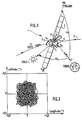
- - la figure 1 est une vue schématique d'un satellite équipé d'un système de contrôle d'orbite autonome conforme à l'invention ;
- - la figure 2 est un schéma simplifié de ce système de contrôle d'orbite géostationnaire autonome ; et
- - la figure 3 est la simulation sur un an de la trace d'un tel satellite.
- - Figure 1 is a schematic view of a satellite equipped with an autonomous orbit control system according to the invention;
- - Figure 2 is a simplified diagram of this autonomous geostationary orbit control system; and
- - Figure 3 is the simulation over a year of the trace of such a satellite.
La figure 1 représente de façon schématique un satellite 1 décrivant une orbite 2 autour de la Terre.FIG. 1 schematically represents a satellite 1 describing an orbit 2 around the Earth.
De façon classique, au satellite 1 est associé un repère de référence X Y Z dont l'axe X est tangent à l'orbite 2, et orienté dans le sens dans lequel l'orbite est parcourue (d'Ouest en Est), et l'axe Z est dirigé vers la Terre (axe géocentrique).Conventionally, satellite 1 is associated with a reference frame XYZ whose axis X is tangent to orbit 2, and oriented in the direction in which the orbit is traversed (from West to East), and the Z axis is directed towards the Earth (geocentric axis).
Le satellite comporte une plate-forme portant des panneaux solaires 3, des réflecteurs 4 et des tuyères de propulsion de tout type connu approprié.The satellite comprises a platform carrying
De façon également connue la plate-forme de ce satellite comporte au moins un capteur terrestre orienté vers la Terre et schématisé en T₁ ainsi qu'une pluralité de détecteurs solaires répartis dans un plan parallèle au plan des axes X et Z et adaptés à être successivement en regard du Soleil au fur et à mesure que le satellite décrit son orbite. Différentes configurations sont connues ; à titre d'exemple, les détecteurs solaires sont ici au nombre de trois : S₁, S₂, S₃, disposés l'un S₂ sur la face tournée vers la Terre et les deux autres, S₁ et S₃, sur les arêtes opposées à cette face.In a manner also known, the platform of this satellite comprises at least one terrestrial sensor oriented towards the Earth and shown diagrammatically in T₁ as well as a plurality of solar detectors distributed in a plane parallel to the plane of the axes X and Z and adapted to be successively facing the Sun as the satellite describes its orbit. Different configurations are known; by way of example, there are three solar detectors here: S₁, S₂, S₃, arranged one S₂ on the face facing the Earth and the other two, S₁ and S₃, on the edges opposite to this face .
Selon l'invention, la plate-forme de ce satellite est également munie, ici sur sa face Nord (à l'opposé de l'axe Y) d'un détecteur stellaire P, de tout type connu approprié, orienté vers le nord, selon l'axe Sud-Nord. Il s'agit par exemple d'un détecteur choisi dans la gamme SODERN ou GALILEO.According to the invention, the platform of this satellite is also provided, here on its north face (opposite the Y axis) with a star detector P, of any suitable known type, oriented towards the north, along the South-North axis. This is for example a detector chosen from the SODERN or GALILEO range.
Ainsi qu'on le sait, il existe actuellement des différences importantes entre les trois types précités de détecteurs, même s'ils sont tous des détecteurs optiques.As is known, there are currently significant differences between the above three types of detectors, even if they are all optical detectors.
Tout d'abord les détecteurs solaires S₁ à S₃, terrestre T₁ et stellaire P se classent respectivement par ordre décroissant du point de vue puissance de rayonnement incident.First of all, the solar detectors S₁ to S₃, terrestrial T₁ and stellar P are classified in decreasing order respectively from the point of view of incident radiation power.
En outre ces détecteurs connus sont sensibles à des gammes différentes de rayonnement : les détecteurs terrestres sont sensibles au rayonnement infra-rouge de la Terre, les détecteurs solaires sont formés de cellules photo-électriques et les détecteurs stellaires sont à base de barrettes ou de réseaux CCD (en anglais "Charge Coupled Device").In addition, these known detectors are sensitive to different ranges of radiation: terrestrial detectors are sensitive to infrared radiation from the Earth, solar detectors are formed from photoelectric cells and stellar detectors are based on bars or networks. CCD (in English "Charge Coupled Device").
Enfin, ces détecteurs comportent classiquement des filtres intégrés induisant des retards différents.Finally, these detectors conventionally include integrated filters inducing different delays.
L'invention utilise la particularité qu'a l'Etoile Polaire d'être la seule étoile de sa magnitude à être toujours dans le champ de vision d'un détecteur stellaire monté sur la face Nord d'un satellite, et donc sa reconnaissance n'exige pas de logiciel sophistiqué.The invention uses the peculiarity that the Polar Star is of being the only star of its magnitude to be always in the field of vision of a stellar detector mounted on the North face of a satellite, and therefore its recognition n 'requires no sophisticated software.
Les détecteurs terrestre T₁, solaires S₁ à S₃ et stellaire P permettent à tout instant de relever l'orientation angulaire de la Terre, du Soleil et de l'Etoile Polaire, respectivement, dans le repère lié au satellite.The terrestrial T₁, solar S₁ to S₃ and stellar P detectors allow the angular orientation of the Earth, the Sun and the Polar Star to be noted at any time, respectively, in the reference frame linked to the satellite.
La figure 2 illustre la structure du système autonome de contrôle d'orbite géostationnaire.Figure 2 illustrates the structure of the autonomous geostationary orbit control system.
Aux détecteurs T₁, S₁ à S₃ et P sont associés des éléments parallèles de filtrage 10, 11 et 12, dans un dispositif de filtrage et de synchronisation dont les sorties sont connectées à un élément de calcul de position 13 suivi d'un élément de calcul de paramètres orbitaux 14 auquel est associé un élément auxiliaire de calibration 15, également connecté à l'élément de calcul de position 13 et relié à une unité de télémétrie 16 en liaison avec le sol. La sortie de l'élément de calcul de paramètres orbitaux est connectée à une unité de calcul et de commande 17 sous le contrôle de laquelle sont placées les tuyères de maintien à poste 18. Une unité de détermination d'attitude 19 est connectée à la fois aux sorties non filtrées des détecteurs T₁, S₁ à S₃ et P et à la sortie de l'élément de calcul des paramètres orbitaux 14. En pratique une mémoire 20 est associée à l'élément de calcul 14 pour stocker les paramètres orbitaux calculés par cet élément 14.To the detectors T₁, S₁ to S₃ and P are associated
En pratique les éléments de calculs 13, 14, 15, 17, 18 peuvent être intégrés au calculateur de bord du satellite.In practice, the
Conformément à l'invention, on choisit de caractériser la position du satellite dans l'espace par la mesure, au même instant, des écarts angulaires α₁ et α₂, existant respectivement, vus du satellite, d'une part entre le Soleil et la Terre, d'autre part entre l'Etoile Polaire et la Terre.According to the invention, we choose to characterize the position of the satellite in space by measuring, at the same time, the angular differences α₁ and α₂, existing respectively, seen from the satellite, on the one hand between the Sun and the Earth. , on the other hand between the North Star and the Earth.
Les modalités de calcul de ces angles α₁ et α₂ accomplies par l'élément de calcul 13, sont à la portée de l'homme de métier.The methods of calculating these angles α₁ and α₂ accomplished by the calculation element 13 are within the reach of the skilled person.
Les grandes lignes de ces calculs peuvent se résumer comme suit, en désignant par RT, RS et RP des repères liés respectivement au détecteur terrestre, aux détecteurs solaires et au détecteur stellaire. On sait définir des matrices de passage PS et PP pour passer des repères RS et RP au repère RT. La mesure des détecteurs solaires et stellaire est constituée par un vecteur unitaire ![]()
![]()
![]()
![]()
Chacun de ces vecteurs peut s'écrire dans le repère RT :

En pratique, pour ramener les mesures des angles α₁ et α₂ exactement au même instant, l'invention propose dans un premier temps, en 10, 11 et 12, de filtrer différemment les mesures brutes des divers détecteurs de manière, non seulement à obtenir un niveau de bruit résiduel prédéterminé approprié, mais aussi à ajouter un retard, différent d'un détecteur à l'autre, tel que le retard global associé à chaque détecteur (ou groupe de détecteurs de même nature), c'est-à-dire la somme du retard propre à chaque détecteur et du retard additionnel induit par le filtre associé 10, 11 ou 12, soit le même pour toutes les mesures. Il en résulte une synchronisation des mesures qui élimine l'influence sur ces mesures de l'attitude qui, elle, est sujette à des variations parfois très rapides.In practice, to bring the measurements of the angles α₁ and α₂ at exactly the same instant, the invention firstly proposes, in 10, 11 and 12, to filter the raw measurements of the various detectors differently so as not only to obtain a appropriate predetermined residual noise level, but also to add a delay, different from one detector to another, such as the overall delay associated with each detector (or group of detectors of the same kind), i.e. the sum of the delay specific to each detector and the additional delay induced by the associated
Le retard global est par exemple choisi égal à 10 secondes.The overall delay is for example chosen to be 10 seconds.
Il est donc possible de ne traiter en 13 un couple d'angles de navigation qu'avec une périodicité modérée, typiquement toutes les dix minutes, ce qui ne représente pas une surcharge significative pour la calculateur de bord.It is therefore possible to process a pair of navigation angles at 13 only with a moderate periodicity, typically every ten minutes, which does not represent a significant overload for the on-board computer.
Soit Z un vecteur de mesure constitué à partir des angles de navigation α₁ et α₂.Let Z be a measurement vector formed from the navigation angles α₁ and α₂.
L'élément de calcul 14 est adapté à déduire le vecteur d'état E regroupant les paramètres orbitaux, selon une formule du type :
Z = H.E. + C.B
où
H est une matrice de mesure
B est un vecteur biais
et C est une matrice de sensibilité aux biais du type :
Xs étant un terme de période voisine de la journée,
YS étant un terme de période voisine de l'année,
YP étant un terme de période voisine du mouvement apparent de l'Etoile Polaire.The
Z = HE + CB
or
H is a measurement matrix
B is a bias vector
and C is a bias sensitivity matrix of the type:
Xs being a term close to the day,
Y S being a term close to the year,
Y P being a term of period close to the apparent movement of the Polar Star.
La détermination des composantes de la matrice de mesure H est de la compétence de l'homme de métier compte tenu des définitions choisies pour les vecteurs Z et E.The determination of the components of the measurement matrix H is within the competence of a person skilled in the art taking into account the definitions chosen for the vectors Z and E.
Il en est de même des composantes de la matrice C.It is the same for the components of the matrix C.
Dans l'exemple qui suit, on a choisi pour les vecteurs Z et E des définitions légèrement différentes de celles données ci-dessus :
- Z = (cos x₁ - cos x1zyn, x₂ - x2zyn) T
où l'indice "syn" est associé à la valeur du paramètre x₁ ou x₂ pour le satellite supposé en orbite géosynchrone idéale non perturbée
et où l'indice "T" traduit une transposition de vecteur ou de matrice ;
- E = (η, ξ, ex, ey, ix, iy)T
où
η = a-azyn
ex = e.cos(Ω + w)
ix = i.cosΩ
ξ = Ω + ω + M-lm
ey = e.sin (Ω + ω)
iy = i.sinΩ
avec M étant l'anomalie moyenne ;
- la matrice H s'écrit alors ![]()
et
où (x₁, y₁, z₁) est le vecteur unitaire (Centre Terre-Soleil) et
où (x₂, y₂, z₂) est le vecteur unitaire (Centre Terre-Polaire).In the following example, we have chosen for the vectors Z and E definitions slightly different from those given above:
- Z = (cos x₁ - cos x 1zyn , x₂ - x 2zyn ) T
where the index "syn" is associated with the value of the parameter x₁ or x₂ for the satellite assumed in ideal undisturbed geosynchronous orbit
and where the index "T" translates a vector or matrix transposition;
- E = (η, ξ, e x , e y , i x , i y ) T
or
η = aa zyn
e x = e.cos (Ω + w)
i x = i.cosΩ
ξ = Ω + ω + Ml m
e y = e.sin (Ω + ω)
i y = i.sinΩ
with M being the mean anomaly;
- the matrix H is then written ![]()
and
where (x₁, y₁, z₁) is the unit vector (Earth-Sun Center) and
where (x₂, y₂, z₂) is the unit vector (Earth-Polar Center).
Quant aux paramètres Xz, Yz et Ypde la matrice C, ils correspondent aux coordonnées de ces mêmes vecteurs unitaires si, en changeant la notation précitée, on écrit ces coordonnées (Xz, Yz, Zz) pour le Soleil et (Xp, Yp, Zp) pour la Polaire.As for the parameters X z , Y z and Y p of the matrix C, they correspond to the coordinates of these same unit vectors if, by changing the abovementioned notation, we write these coordinates (X z , Y z , Z z ) for the Sun and (X p , Y p , Z p ) for Polar.
Comme cela a été déjà précisé, la forme de H dépend de la forme précise choisie pour Z et E.As already stated, the form of H depends on the precise form chosen for Z and E.
Le vecteur biais B a pour objet de rendre compte des erreurs internes et des erreurs d'alignement des détecteurs.The purpose of the bias vector B is to account for the internal errors and the alignment errors of the detectors.
Même si ces erreurs étaient soigneusement calibrées au sol, l'environnement et le déroulement du lancement seraient susceptibles de les modifier.Even if these errors were carefully calibrated on the ground, the environment and the launch procedure could modify them.
D'autre part, leur calibration en vol, individuellement, est actuellement reconnue comme impossible car ces biais ou écarts ne sont pas observables.On the other hand, their calibration in flight, individually, is currently recognized as impossible because these biases or deviations are not observable.
Il a été cependant constaté, dans le cadre de l'invention, qu'il était possible d'évaluer globalement l'effet de tous ces biais sur les deux angles de navigation grâce à une matrice de sensibilité aux biais du type précité.However, it has been found, within the framework of the invention, that it was possible to globally assess the effect of all these biases on the two navigation angles thanks to a bias sensitivity matrix of the aforementioned type.
Selon l'invention la procédure de calibration de ces biais est la suivante : le sol détermine régulièrement (par exemple après la mise en orbite puis tous les ans) la position du satellite et ses paramètres orbitaux puis télécharge à ce dernier, grâce à l'unité de télémétrie 16, ces paramètres d'orbite et/ou les angles de navigation associés. Les paramètres sont alors traités, de même que la valeur Z déduite des mesures des détecteurs, par l'élément auxiliaire de calcul 15 qui en déduit la nouvelle valeur du vecteur biais B. Le vecteur biais, une fois estimé à l'issue d'une période d'une dizaine de jours, est stocké dans cet élément 15 jusqu'à la prochaine calibration. La fonction calcul de cet élément 15 peut alors être désactivée pour ne pas solliciter inutilement le calculateur de bord.According to the invention, the procedure for calibrating these biases is as follows: the ground regularly determines (for example after putting into orbit then every year) the position of the satellite and its orbital parameters then downloads to the latter, thanks to the
L'élément de calcul 14 est en fait un filtre estimateur d'orbite ; il s'agit par exemple d'un filtre KALMAN, dont les équations sont bien connues de l'homme de métier.The
L'élément auxiliaire de calcul 15 est en pratique un filtre, par exemple du type FRIEDLAND dont les équations sont également connues. Elles permettent d'évaluer B à partir de plusieurs mesures.The
Des simulations effectuées sur un an ont permis de vérifier qu'il était possible de maintenir ainsi un satellite dans une fenêtre de 0,05 degré, aussi bien en longitude qu'en latitude (voir la figure 3) avec pour les paramètres orbitaux, la précision suivante (trois fois l'écart-type) :
sur a : 50 m
sur ex : 3,5 10⁻⁵
sur ey : 3,5.10⁻⁵
sur ix et iy : 0,001 degré
sur la longitude : 0,005 degré.Simulations carried out over a year made it possible to verify that it was possible to maintain a satellite in a 0.05 degree window, both in longitude and in latitude (see Figure 3) with for the orbital parameters, the following precision (three times the standard deviation):
on a: 50 m
on e x : 3.5 10⁻⁵
on e y : 3.5.10⁻⁵
on i x and i y : 0.001 degree
on longitude: 0.005 degrees.
Les mesures brutes des détecteurs (avant filtrage, donc correspondant à des instants légèrement différents) peuvent être utilisées pour, grâce à l'élément 18, déterminer les trois angles d'attitude du satellite (roulis, lacet, tangage) à partir de la connaissance des paramètres orbitaux fournis par l'élément 14, donc de façon autonome (les constantes de temps des filtres intétgrés aux détecteurs sont couramment environ de quelques dixièmes de seconde pour les détecteurs solaires, de 0,5 seconde pour le détecteur terrestres, et de 0,1 à 0,5 seconde pour le détecteur stellaire).The raw measurements of the detectors (before filtering, therefore corresponding to slightly different times) can be used to, thanks to
Le système de la figure 2 constitue donc une système entièrement autonome de détermination aussi bien de l'orbite que de l'attitude.The system of FIG. 2 therefore constitutes a completely autonomous system for determining both the orbit and the attitude.
Il va de soi que la description qui précède n'a été proposée qu'à titre illustratif non limitatif et que de nombreuses variantes peuvent être proposées par l'homme de métier sans sortir du cadre de l'invention, notamment en ce qui concerne la disposition des détecteurs solaires.It goes without saying that the foregoing description has been offered only by way of nonlimiting illustration and that numerous variants can be proposed by those skilled in the art without departing from the scope of the invention, in particular as regards the arrangement of solar detectors.
Claims (6)
- on détermine au même instant l'angle α₁ entre la direction (Satellite-Soleil) et la direction (Satellite-Terre), et l'angle α₂ entre la direction (Satellite-Etoile Polaire) et la direction (Satellite-Terre),
- on en déduit le vecteur d'état E formé des paramètres orbitaux par la formule :
Z = H.E + C.B
où :
. Z est un vecteur de mesure dont les composantes sont déduites des angles α₁ et α₂
. H est une matrice de mesure
. C est une matrice de sensibilité aux biais de forme

. B est un vecteur biais déterminé préalablement par comparaison entre le vecteur Z mesuré et des mesures faites au sol,
- on détermine en conséquence et on applique par des tuyères des manoeuvres de maintien à poste.1. Method for maintaining a satellite in geostationary orbit, characterized in that:
- the angle α₁ between the direction (Satellite-Sun) and the direction (Satellite-Earth) is determined at the same time, and the angle α₂ between the direction (Satellite-Polar Star) and the direction (Satellite-Earth),
- we deduce the state vector E formed from the orbital parameters by the formula:
Z = HE + CB
or :
. Z is a measurement vector whose components are deduced from the angles α₁ and α₂
. H is a measurement matrix
. It is a matrix of sensitivity to shape bias
. B is a bias vector determined beforehand by comparison between the measured vector Z and measurements made on the ground,
- We determine accordingly and apply by nozzles maintenance maneuvers at the post.
- au moins un détecteur terrestre (T₁) muni d'un filtre (10) adapté à générer un retard tel que le retard global (retard propre du détecteur + retard du filtre) ait une valeur prédéterminée,
- une pluralité de détecteurs solaires (S₁, S₂, S₃) munie d'un filtre (11) adapté à générer un retard tel que le retard global soit égal à ladite valeur prédéterminée,
- au moins un détecteur stellaire (P) orienté vers le Nord selon l'axe Sud-Nord du satellite muni d'un filtre (12) adapté à générer un retard tel que le retard global soit égal à ladite valeur prédéterminée,
- un élément de calcul de position (13) connecté à ces filtres et adapté à déduire des mesures filtrées desdits détecteurs (T₁, S₁-S₃, P) l'angle α₁ entre les directions (Satellite-Soleil) et (Satellite-Terre) et l'angle α₂ entre les directions (Satellite-Etoile Polaire) et (Satellite-Terre),
- un élément (14) de calcul de paramètres orbitaux connecté à la sortie de l'élément de calcul de position (13) et adapté à déterminer le vecteur d'état E du satellite, composé des paramètres orbitaux selon la formule :
Z = H.E + C.B
où :
. Z est un vecteur de mesure dont les composantes sont déduites des angles α₁ et α₂
. H est une matrice de mesure
. C est une matrice de sensibilité aux biais de forme

. B est un vecteur biais déterminé préalablement par comparaison entre le vecteur Z mesuré et des mesures faites au sol,
- un élément auxiliaire de calcul de biais (15) connecté à la sortie de l'élément de calcul de position (13), à une unité de télémétrie (16) en liaison avec le sol, et dont la sortie est connectée à l'élément de calcul de paramètres orbitaux, adapté à déterminer et mémoriser le vecteur biais B par comparaison du vecteur E avec des mesures correspondantes venues du sol, et
- une unité de commande (17) reliée à des tuyères de maintien à poste.3. Station keeping system comprising:
at least one terrestrial detector (T₁) provided with a filter (10) adapted to generate a delay such that the overall delay (own delay of the detector + delay of the filter) has a predetermined value,
- a plurality of solar detectors (S₁, S₂, S₃) provided with a filter (11) adapted to generate a delay such that the overall delay is equal to said predetermined value,
- at least one star detector (P) oriented towards the North along the South-North axis of the satellite fitted with a filter (12) adapted to generate a delay such that the overall delay is equal to said predetermined value,
a position calculating element (13) connected to these filters and adapted to deduce from the filtered measurements of said detectors (T₁, S₁-S₃, P) the angle α₁ between the directions (Satellite-Sun) and (Satellite-Earth) and the angle α₂ between the directions (Satellite-Polar Star) and (Satellite-Earth),
an element (14) for calculating orbital parameters connected to the output of the position calculating element (13) and adapted to determine the state vector E of the satellite, composed of the orbital parameters according to the formula:
Z = HE + CB
or :
. Z is a measurement vector whose components are deduced from the angles α₁ and α₂
. H is a measurement matrix
. It is a matrix of sensitivity to shape bias
. B is a bias vector determined beforehand by comparison between the measured vector Z and measurements made on the ground,
- an auxiliary bias calculation element (15) connected to the output of the position calculation element (13), to a telemetry unit (16) in connection with the ground, and the output of which is connected to the element for calculating orbital parameters, suitable for determining and storing the bias vector B by comparison of the vector E with corresponding measurements from the ground, and
- a control unit (17) connected to station holding nozzles.
Applications Claiming Priority (2)
| Application Number | Priority Date | Filing Date | Title |
|---|---|---|---|
| FR888813121A FR2637564B1 (en) | 1988-10-06 | 1988-10-06 | METHOD AND SYSTEM FOR AUTONOMOUS ORBIT CONTROL OF A GEOSTATIONARY SATELLITE |
| FR8813121 | 1988-10-06 |
Publications (2)
| Publication Number | Publication Date |
|---|---|
| EP0363243A1 true EP0363243A1 (en) | 1990-04-11 |
| EP0363243B1 EP0363243B1 (en) | 1993-12-29 |
Family
ID=9370753
Family Applications (1)
| Application Number | Title | Priority Date | Filing Date |
|---|---|---|---|
| EP89402567A Expired - Lifetime EP0363243B1 (en) | 1988-10-06 | 1989-09-19 | Method and system for autonomously controlling the orbit of a geostationary satellite |
Country Status (7)
| Country | Link |
|---|---|
| US (1) | US5108050A (en) |
| EP (1) | EP0363243B1 (en) |
| JP (1) | JP2847302B2 (en) |
| CA (1) | CA2000214C (en) |
| DE (1) | DE68911830T2 (en) |
| ES (1) | ES2047695T3 (en) |
| FR (1) | FR2637564B1 (en) |
Cited By (6)
| Publication number | Priority date | Publication date | Assignee | Title |
|---|---|---|---|---|
| FR2661261A1 (en) * | 1990-04-19 | 1991-10-25 | Gen Electric | THREE-DIMENSIONAL ATTITUDE CONTROL OF A SPACE MACHINE USING A POLAR STAR DETECTOR. |
| FR2670886A1 (en) * | 1990-12-21 | 1992-06-26 | Aerospatiale | METHOD FOR REACQUIRING ATTITUDE BY STAR RECOGNITION FOR 3-AXIS STABILIZED SATELLITE |
| FR2670746A1 (en) * | 1990-12-21 | 1992-06-26 | Aerospatiale | ATTITUDE CONTROL SYSTEM FOR 3-AXIS SATELLITE; IN PARTICULAR FOR SATELLITE OBSERVATION. |
| EP0496879A1 (en) * | 1990-08-22 | 1992-08-05 | Microcosm Inc | Satellite orbit maintenance system. |
| DE4129630A1 (en) * | 1991-09-06 | 1993-05-06 | Deutsche Aerospace Ag, 8000 Muenchen, De | MEASURING ARRANGEMENT AND CONTROL SYSTEM FOR THE POSITION CONTROL OF A THREE-AXIS-STABILIZED SATELLITE AND RELATED MEASURING AND CONTROL PROCEDURES |
| EP0748737A1 (en) * | 1995-05-24 | 1996-12-18 | Daimler-Benz Aerospace Aktiengesellschaft | Three-axis-stabilized earth satellite and corresponding sun and earth acquisition manoeuvers |
Families Citing this family (20)
| Publication number | Priority date | Publication date | Assignee | Title |
|---|---|---|---|---|
| DE19703629A1 (en) * | 1997-01-31 | 1998-08-06 | Daimler Benz Aerospace Ag | Method for autonomously determining the position of a satellite |
| US5562266A (en) * | 1992-10-29 | 1996-10-08 | Aerospatiale Societe Nationale Industrielle | Rate gyro calibration method and apparatus for a three-axis stabilized satellite |
| FR2697651B1 (en) * | 1992-10-29 | 1995-02-03 | Aerospatiale | Method and apparatus for calibrating the gyros of a stabilized 3-axis satellite. |
| US5452869A (en) * | 1992-12-18 | 1995-09-26 | Hughes Aircraft Company | On-board three-axes attitude determination and control system |
| RU2033949C1 (en) * | 1993-02-09 | 1995-04-30 | Севастиян Дмитриевич Гнатюк | Self-contained on-board control system for space vehicle |
| US5452077A (en) * | 1993-12-09 | 1995-09-19 | Hughes Aircraft Company | Transient-free method of determining satellite attitude |
| US6098929A (en) * | 1998-01-28 | 2000-08-08 | Falbel; Gerald | Three axis attitude readout system for geosynchronous spacecraft |
| US6145790A (en) * | 1998-09-22 | 2000-11-14 | Hughes Electronics Corporation | Attitude determination system and method |
| EP1076005B1 (en) * | 1999-08-13 | 2007-01-03 | Hughes Electronics Corporation | Spacecraft orbit control using orbit position feedback |
| US6691033B1 (en) * | 2000-07-26 | 2004-02-10 | Hughes Electronics Corporation | System and method for calibrating inter-star-tracker misalignments in a stellar inertial attitude determination system |
| US7454272B1 (en) * | 2005-08-25 | 2008-11-18 | Raytheon Company | Geostationary stationkeeping method |
| US8174433B1 (en) | 2009-02-26 | 2012-05-08 | Raytheon Company | Bias estimation and orbit determination |
| US9091552B2 (en) * | 2011-10-25 | 2015-07-28 | The Boeing Company | Combined location and attitude determination system and methods |
| FR2983981B1 (en) * | 2011-12-09 | 2014-08-22 | Thales Sa | METHOD AND SYSTEM FOR CONTROLLING A SET OF AT LEAST TWO SATELLITES, DESIGNED TO PROVIDE SERVICE ON A GEOSTATIONARY ORBIT, DELIVERING THIS SERVICE TO A NON-GEOSTATIONARY ORBIT |
| US9073648B2 (en) * | 2013-02-15 | 2015-07-07 | The Boeing Company | Star tracker rate estimation with kalman filter enhancement |
| CN111238567A (en) * | 2020-01-06 | 2020-06-05 | 航天恒星科技有限公司 | Satellite in-orbit health monitoring device |
| CN112052560A (en) * | 2020-07-30 | 2020-12-08 | 上海航天控制技术研究所 | Closed-loop simulation design method for system-level on-board computer maintenance mode |
| CN112319850B (en) * | 2020-09-30 | 2022-05-24 | 中国卫通集团股份有限公司 | Method and device for automatically keeping position of synchronous orbit satellite |
| CN112526561B (en) * | 2020-11-27 | 2024-04-23 | 中国科学院国家天文台 | Method for prolonging forecasting period of two ephemeris of geostationary orbit communication satellite |
| CN112769466B (en) * | 2020-12-22 | 2022-08-12 | 火眼位置数智科技服务有限公司 | Low-orbit satellite constellation configuration keeping method |
Citations (5)
| Publication number | Priority date | Publication date | Assignee | Title |
|---|---|---|---|---|
| DE3417661A1 (en) * | 1983-05-13 | 1984-11-15 | Mitsubishi Denki K.K., Tokio/Tokyo | System for controlling the orientation of an artificial satellite |
| EP0174715A2 (en) * | 1984-09-13 | 1986-03-19 | Mitsubishi Denki Kabushiki Kaisha | Attitude angle calculation apparatus for a geostationary satellite |
| EP0209429A1 (en) * | 1985-06-20 | 1987-01-21 | Matra | Method and device for placing a 3-axis stabilized satellite into a geostationary orbit |
| EP0251808A2 (en) * | 1986-07-04 | 1988-01-07 | The Marconi Company Limited | Satellite attitude control |
| EP0267086A1 (en) * | 1986-10-16 | 1988-05-11 | Centre National D'etudes Spatiales | Spacecraft with an antenna earth pointing device |
Family Cites Families (2)
| Publication number | Priority date | Publication date | Assignee | Title |
|---|---|---|---|---|
| US4617634A (en) * | 1983-06-28 | 1986-10-14 | Mitsubishi Denki Kabushiki Kaisha | Artificial satellite attitude control system |
| GB8809247D0 (en) * | 1988-04-20 | 1988-05-25 | British Aerospace | Attitude recovery for spacecraft |
-
1988
- 1988-10-06 FR FR888813121A patent/FR2637564B1/en not_active Expired - Fee Related
-
1989
- 1989-09-19 ES ES89402567T patent/ES2047695T3/en not_active Expired - Lifetime
- 1989-09-19 DE DE89402567T patent/DE68911830T2/en not_active Expired - Lifetime
- 1989-09-19 EP EP89402567A patent/EP0363243B1/en not_active Expired - Lifetime
- 1989-10-03 US US07/416,694 patent/US5108050A/en not_active Expired - Fee Related
- 1989-10-05 JP JP1261230A patent/JP2847302B2/en not_active Expired - Lifetime
- 1989-10-05 CA CA002000214A patent/CA2000214C/en not_active Expired - Fee Related
Patent Citations (5)
| Publication number | Priority date | Publication date | Assignee | Title |
|---|---|---|---|---|
| DE3417661A1 (en) * | 1983-05-13 | 1984-11-15 | Mitsubishi Denki K.K., Tokio/Tokyo | System for controlling the orientation of an artificial satellite |
| EP0174715A2 (en) * | 1984-09-13 | 1986-03-19 | Mitsubishi Denki Kabushiki Kaisha | Attitude angle calculation apparatus for a geostationary satellite |
| EP0209429A1 (en) * | 1985-06-20 | 1987-01-21 | Matra | Method and device for placing a 3-axis stabilized satellite into a geostationary orbit |
| EP0251808A2 (en) * | 1986-07-04 | 1988-01-07 | The Marconi Company Limited | Satellite attitude control |
| EP0267086A1 (en) * | 1986-10-16 | 1988-05-11 | Centre National D'etudes Spatiales | Spacecraft with an antenna earth pointing device |
Cited By (11)
| Publication number | Priority date | Publication date | Assignee | Title |
|---|---|---|---|---|
| FR2661261A1 (en) * | 1990-04-19 | 1991-10-25 | Gen Electric | THREE-DIMENSIONAL ATTITUDE CONTROL OF A SPACE MACHINE USING A POLAR STAR DETECTOR. |
| EP0496879A1 (en) * | 1990-08-22 | 1992-08-05 | Microcosm Inc | Satellite orbit maintenance system. |
| EP0496879A4 (en) * | 1990-08-22 | 1992-08-12 | Microcosm, Inc. | Satellite orbit maintenance system |
| US5277385A (en) * | 1990-12-12 | 1994-01-11 | Aerospatiale Societe Nationale Industrielle | Method of attitude reacquisition for three-axis stabilized satellites using star recognition |
| FR2670886A1 (en) * | 1990-12-21 | 1992-06-26 | Aerospatiale | METHOD FOR REACQUIRING ATTITUDE BY STAR RECOGNITION FOR 3-AXIS STABILIZED SATELLITE |
| FR2670746A1 (en) * | 1990-12-21 | 1992-06-26 | Aerospatiale | ATTITUDE CONTROL SYSTEM FOR 3-AXIS SATELLITE; IN PARTICULAR FOR SATELLITE OBSERVATION. |
| EP0493143A1 (en) * | 1990-12-21 | 1992-07-01 | AEROSPATIALE Société Nationale Industrielle | Attitude control system for a three-axis stabilized satellite, particularly for an observation satellite |
| EP0493228A1 (en) * | 1990-12-21 | 1992-07-01 | AEROSPATIALE Société Nationale Industrielle | Method of attitude recognition for a three axis stabilized satellite using star recognition |
| US5279483A (en) * | 1990-12-21 | 1994-01-18 | Aerospatiale Societe Nationale Industrielle | Attitude control system for a three-axis stabilized satellite especially a remote sensing satellite |
| DE4129630A1 (en) * | 1991-09-06 | 1993-05-06 | Deutsche Aerospace Ag, 8000 Muenchen, De | MEASURING ARRANGEMENT AND CONTROL SYSTEM FOR THE POSITION CONTROL OF A THREE-AXIS-STABILIZED SATELLITE AND RELATED MEASURING AND CONTROL PROCEDURES |
| EP0748737A1 (en) * | 1995-05-24 | 1996-12-18 | Daimler-Benz Aerospace Aktiengesellschaft | Three-axis-stabilized earth satellite and corresponding sun and earth acquisition manoeuvers |
Also Published As
| Publication number | Publication date |
|---|---|
| DE68911830T2 (en) | 1994-04-28 |
| CA2000214C (en) | 1993-12-21 |
| EP0363243B1 (en) | 1993-12-29 |
| US5108050A (en) | 1992-04-28 |
| JP2847302B2 (en) | 1999-01-20 |
| FR2637564A1 (en) | 1990-04-13 |
| DE68911830D1 (en) | 1994-02-10 |
| CA2000214A1 (en) | 1990-04-06 |
| FR2637564B1 (en) | 1994-10-14 |
| ES2047695T3 (en) | 1994-03-01 |
| JPH02156312A (en) | 1990-06-15 |
Similar Documents
| Publication | Publication Date | Title |
|---|---|---|
| EP0363243B1 (en) | Method and system for autonomously controlling the orbit of a geostationary satellite | |
| EP0435708B1 (en) | Control method of the attitude with respect to the roll- and the gear axis for a satellite | |
| EP0571239B1 (en) | Process and device for earth acquisition via the polar star for triaxially stabilised satellite on a small inclination orbit | |
| EP2181923B1 (en) | Method and system for desaturating the inertia wheels in a spacecraft | |
| EP0363244A1 (en) | Method for active control by means of three attitude axes of a geostationary satellite | |
| EP0076179B1 (en) | Process to align the roll axis of a satellite with a desired direction | |
| FR2705448A1 (en) | System and method for determining the attitude of a spacecraft using stellar or terrestrial sensors | |
| EP0603058B1 (en) | Method for controlling the attitude of a satellite directed towards a celestial object and a satellite for implementing the same | |
| EP0199648B1 (en) | Method and device for a satellite nutation damper by mass location control | |
| EP0493228B1 (en) | Method of attitude recognition for a three axis stabilized satellite using star recognition | |
| EP3201091B1 (en) | Method of supervising attitude of a satellite in survival mode, adapted satellite and method of remotely controlling such a satellite | |
| EP0209429B1 (en) | Method and device for placing a 3-axis stabilized satellite into a geostationary orbit | |
| EP3921235B1 (en) | Method for attitude control of a satellite in survival mode without a priori knowledge of the local time of the satellite's orbit | |
| CA1267949A (en) | Rapid repointing method for earth pointed satellites, particularly inertia wheel stabilized geostationary telecommunication satellites | |
| EP0341130B1 (en) | Method for slewing the inertial moment of a spinning body in space up to a given direction | |
| EP0678732B1 (en) | Procedure and device for calibrating the gyrometers of a three-axis stabilized satellite | |
| EP1635485B1 (en) | Optical transmission method between an on-board spacecraft terminal and a distant terminal, and spacecraft adapted for said method | |
| EP0717264B1 (en) | Procedure and device for estimating gyrometric biases | |
| EP4183066B1 (en) | Method for transmitting data by a spacecraft comprising a laser emission module | |
| FR2701762A1 (en) | Device for restoring the orbit of celestial bodies, particularly artificial satellites, by means of deviation. | |
| FR3137190A1 (en) | MANEUVERING SATELLITES WITHOUT VARIATION DETECTORS | |
| FR2756065A1 (en) | APPARATUS AND METHOD FOR CONTROLLING THE ATTITUDE OF A SATELLITE WITH RESPECT TO THREE AXES USING A SUN DETECTOR MOUNTED ON A SOLAR PANEL | |
| Hadj-Sahraoui et al. | Earth observation payload predimensioning software |
Legal Events
| Date | Code | Title | Description |
|---|---|---|---|
| PUAI | Public reference made under article 153(3) epc to a published international application that has entered the european phase |
Free format text: ORIGINAL CODE: 0009012 |
|
| AK | Designated contracting states |
Kind code of ref document: A1 Designated state(s): DE ES GB IT NL SE |
|
| 17P | Request for examination filed |
Effective date: 19900518 |
|
| 17Q | First examination report despatched |
Effective date: 19920430 |
|
| GRAA | (expected) grant |
Free format text: ORIGINAL CODE: 0009210 |
|
| AK | Designated contracting states |
Kind code of ref document: B1 Designated state(s): DE ES GB IT NL SE |
|
| PG25 | Lapsed in a contracting state [announced via postgrant information from national office to epo] |
Ref country code: NL Effective date: 19931229 |
|
| ITF | It: translation for a ep patent filed |
Owner name: JACOBACCI & PERANI S.P. |
|
| REF | Corresponds to: |
Ref document number: 68911830 Country of ref document: DE Date of ref document: 19940210 |
|
| REG | Reference to a national code |
Ref country code: ES Ref legal event code: FG2A Ref document number: 2047695 Country of ref document: ES Kind code of ref document: T3 |
|
| GBT | Gb: translation of ep patent filed (gb section 77(6)(a)/1977) |
Effective date: 19940218 |
|
| NLV1 | Nl: lapsed or annulled due to failure to fulfill the requirements of art. 29p and 29m of the patents act | ||
| PLBE | No opposition filed within time limit |
Free format text: ORIGINAL CODE: 0009261 |
|
| STAA | Information on the status of an ep patent application or granted ep patent |
Free format text: STATUS: NO OPPOSITION FILED WITHIN TIME LIMIT |
|
| 26N | No opposition filed | ||
| EAL | Se: european patent in force in sweden |
Ref document number: 89402567.5 |
|
| PGFP | Annual fee paid to national office [announced via postgrant information from national office to epo] |
Ref country code: GB Payment date: 19980909 Year of fee payment: 10 |
|
| PGFP | Annual fee paid to national office [announced via postgrant information from national office to epo] |
Ref country code: DE Payment date: 19980917 Year of fee payment: 10 |
|
| PGFP | Annual fee paid to national office [announced via postgrant information from national office to epo] |
Ref country code: SE Payment date: 19980922 Year of fee payment: 10 |
|
| PGFP | Annual fee paid to national office [announced via postgrant information from national office to epo] |
Ref country code: ES Payment date: 19980930 Year of fee payment: 10 |
|
| PG25 | Lapsed in a contracting state [announced via postgrant information from national office to epo] |
Ref country code: GB Free format text: LAPSE BECAUSE OF NON-PAYMENT OF DUE FEES Effective date: 19990919 |
|
| PG25 | Lapsed in a contracting state [announced via postgrant information from national office to epo] |
Ref country code: ES Free format text: LAPSE BECAUSE OF NON-PAYMENT OF DUE FEES Effective date: 19990920 |
|
| PG25 | Lapsed in a contracting state [announced via postgrant information from national office to epo] |
Ref country code: SE Free format text: THE PATENT HAS BEEN ANNULLED BY A DECISION OF A NATIONAL AUTHORITY Effective date: 19990929 |
|
| GBPC | Gb: european patent ceased through non-payment of renewal fee |
Effective date: 19990919 |
|
| EUG | Se: european patent has lapsed |
Ref document number: 89402567.5 |
|
| PG25 | Lapsed in a contracting state [announced via postgrant information from national office to epo] |
Ref country code: DE Free format text: LAPSE BECAUSE OF NON-PAYMENT OF DUE FEES Effective date: 20000701 |
|
| REG | Reference to a national code |
Ref country code: ES Ref legal event code: FD2A Effective date: 20001013 |
|
| PG25 | Lapsed in a contracting state [announced via postgrant information from national office to epo] |
Ref country code: IT Free format text: LAPSE BECAUSE OF NON-PAYMENT OF DUE FEES Effective date: 20050919 |