EP0363220B1 - Appareil pour couper en cubes - Google Patents
Appareil pour couper en cubes Download PDFInfo
- Publication number
- EP0363220B1 EP0363220B1 EP19890310260 EP89310260A EP0363220B1 EP 0363220 B1 EP0363220 B1 EP 0363220B1 EP 19890310260 EP19890310260 EP 19890310260 EP 89310260 A EP89310260 A EP 89310260A EP 0363220 B1 EP0363220 B1 EP 0363220B1
- Authority
- EP
- European Patent Office
- Prior art keywords
- feed
- product
- roll
- knife roll
- drum
- Prior art date
- Legal status (The legal status is an assumption and is not a legal conclusion. Google has not performed a legal analysis and makes no representation as to the accuracy of the status listed.)
- Expired - Lifetime
Links
- 238000005520 cutting process Methods 0.000 claims description 29
- 230000002093 peripheral effect Effects 0.000 claims description 25
- 238000000034 method Methods 0.000 claims description 5
- 235000013372 meat Nutrition 0.000 description 16
- 235000013305 food Nutrition 0.000 description 15
- 235000013622 meat product Nutrition 0.000 description 8
- 230000000712 assembly Effects 0.000 description 3
- 238000000429 assembly Methods 0.000 description 3
- 239000000463 material Substances 0.000 description 3
- 230000000979 retarding effect Effects 0.000 description 3
- 230000000694 effects Effects 0.000 description 2
- 235000013311 vegetables Nutrition 0.000 description 2
- 239000000853 adhesive Substances 0.000 description 1
- 230000001070 adhesive effect Effects 0.000 description 1
- 239000010868 animal carcass Substances 0.000 description 1
- 230000007812 deficiency Effects 0.000 description 1
- 238000013461 design Methods 0.000 description 1
- 238000007599 discharging Methods 0.000 description 1
- 235000013399 edible fruits Nutrition 0.000 description 1
- 238000005516 engineering process Methods 0.000 description 1
- 238000012423 maintenance Methods 0.000 description 1
- 239000002184 metal Substances 0.000 description 1
- 239000002245 particle Substances 0.000 description 1
- 238000012545 processing Methods 0.000 description 1
- 125000006850 spacer group Chemical group 0.000 description 1
- 239000000126 substance Substances 0.000 description 1
- 238000006467 substitution reaction Methods 0.000 description 1
- 238000012546 transfer Methods 0.000 description 1
Images


Classifications
-
- B—PERFORMING OPERATIONS; TRANSPORTING
- B26—HAND CUTTING TOOLS; CUTTING; SEVERING
- B26D—CUTTING; DETAILS COMMON TO MACHINES FOR PERFORATING, PUNCHING, CUTTING-OUT, STAMPING-OUT OR SEVERING
- B26D7/00—Details of apparatus for cutting, cutting-out, stamping-out, punching, perforating, or severing by means other than cutting
- B26D7/06—Arrangements for feeding or delivering work of other than sheet, web, or filamentary form
- B26D7/0625—Arrangements for feeding or delivering work of other than sheet, web, or filamentary form by endless conveyors, e.g. belts
-
- B—PERFORMING OPERATIONS; TRANSPORTING
- B26—HAND CUTTING TOOLS; CUTTING; SEVERING
- B26D—CUTTING; DETAILS COMMON TO MACHINES FOR PERFORATING, PUNCHING, CUTTING-OUT, STAMPING-OUT OR SEVERING
- B26D3/00—Cutting work characterised by the nature of the cut made; Apparatus therefor
- B26D3/18—Cutting work characterised by the nature of the cut made; Apparatus therefor to obtain cubes or the like
- B26D3/22—Cutting work characterised by the nature of the cut made; Apparatus therefor to obtain cubes or the like using rotating knives
-
- B—PERFORMING OPERATIONS; TRANSPORTING
- B26—HAND CUTTING TOOLS; CUTTING; SEVERING
- B26D—CUTTING; DETAILS COMMON TO MACHINES FOR PERFORATING, PUNCHING, CUTTING-OUT, STAMPING-OUT OR SEVERING
- B26D7/00—Details of apparatus for cutting, cutting-out, stamping-out, punching, perforating, or severing by means other than cutting
- B26D7/06—Arrangements for feeding or delivering work of other than sheet, web, or filamentary form
- B26D7/0683—Arrangements for feeding or delivering work of other than sheet, web, or filamentary form specially adapted for elongated articles
Definitions
- the present invention generally involves the field of technology pertaining to methods and apparatus for sectionalizing cuttable material into discrete particles of predetermined shape and size. More specifically, the invention relates to an improved machine for cutting a food product, particularly slabs of fresh or frozen tempered meat, into diced sections.
- Machines for sectionalizing or dividing materials into smaller discrete portions through a series of cutting operations are well known in the art. Such machines are particularly suited for cutting food products, such as vegetables and fruits, into discrete pieces having a substantially rectangular or diced configuration. This is generally accomplished by conveying a large piece of the food product through a rotating bank of circular knives which initially cut the product into a plurality of elongate strips that are thereafter directed into a crosscut assembly wherein a rotating bank of elongate knives effect transverse cutting of the strips into diced sections.
- the bank of circular knives is associated with either a rotating feed drum or a stationary transfer plate, and defines a throat therebetween for receiving the conveyed product.
- the bank of elongate knives is provided with an associated stationary stripper plate having a cooperating shear edge against which the transverse cutting of the strips is accomplished.
- the conveyor assembly includes a driven, generally horizontal feed belt for supporting and conveying the product, whereby the feed roll is positioned near an end of the feed belt, a carriage supporting the feed roll for vertical movement and biasing means operatively associated with the feed roll to resiliently bias the feed roll against the product on the feed belt and the rotatable feed drum having said peripheral surface defines a plurality of circumferentially spaced grooves extending generally across the product feed path adapted to contact the product so as to retard the movement of the product through the feed throat.
- an improved machine for sectionalizing cuttable material into discrete pieces of a desired size and configuration which can efficiently and reliably produce diced sections of food products at high speeds, and is particularly suited for producing discrete diced sections from slabs of flesh or frozen tempered meat.
- the invention also extends to a method of cutting a product into a plurality of diced sections using the apparatus of claim 1 characterised in that the conveyor assembly includes a driven, generally horizontal feed belt for supporting and conveying the product, whereby the feed roll is positioned near an end of the feed belt, a carriage supporting the feed roll for vertical movement and biasing means operatively associated with the feed roll to resiliently bias the feed roll against the product on the feed belt and the rotatable feed drum having said peripheral surface defines a plurality of circumferentially spaced grooves extending generally across the product feed path adapted to contact the product so as to retard the movement of the product through the feed throat.
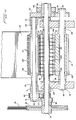
- a dicing machine 1 shall now be described with initial reference to Figs. 1 and 2.
- machine 1 is mounted on a rectangular-shaped support frame 3 by bolting a component support base 5 of machine 1 to a plurality of inwardly directed plates 7.
- Frame 3 includes a plurality of legs 9 sized to support machine 1 at a desired height.
- Frame 3 may be of any appropriate conventional design and is preferably formed from tubular or channel-shaped metal members welded or bolted together.
- Machine 1 includes an electric motor 11 for driving a pulley and gear assembly 13 which rotates the corresponding drive shafts of all of the components in a manner to be hereinafter detailed.
- Pulley and gear assembly 13 and its associated components are housed within a hood assembly 15 which permits easy access to assembly 13 and its components for maintenance purposes.
- a discharge chute 17 extends outwardly from hood 15 and frame 3 for discharging diced product DP produced by machine 1.
- the operation of machine 1 may be controlled by an appropriate known electrical or electronic system housed in a control box 19, through which electrical power may be transmitted to motor 11 for driving pulley and gear assembly 13.
- Machine 1 also includes a conveyor assembly 21 which comprises a horizontal feed belt 23 provided with a driven roll 25 and an idler roll 27. Roll 25 is driven by a gear 26 in a manner to be later described.
- assembly 13 includes a main drive pulley 29 mounted on a main drive shaft 31 which is rotated by the power output shaft of motor 11 through a main drive belt 33.
- Assembly 13 is supported on a pair of spaced side frames 35 and 37 which extend vertically from support base 5.
- a crossbar 43 is clamped in side frames 35 and 37.
- a driveshaft 45 of a crosscut assembly 47 is supported in side frames 35 and 37.
- a stripper plate 49, forming a portion of crosscut assembly 47, is also bolted to crossbar 43.
- Drive shaft 45 of crosscut assembly 47 is provided with a gear 51 which is engaged with and driven by a larger gear 53 mounted on main drive shaft 31 opposite drive pulley 29.
- a main drive gear 55 is also mounted on drive shaft 31 inwardly of drive pulley 29 and is in driving engagement with a secondary drive gear 57 for rotating a drive shaft 59.
- Rotation of main drive shaft 31 also drives a secondary pulley 61 through a secondary drive belt 63 for rotating a drive shaft 65.
- a feed roll 67 forming a part of conveyor assembly 21, is supported for rotation on drive shaft 65, with the latter being supported at its opposite ends on a carrier frame 69.
- Roll 67 may be provided with a plurality of longitudinal grooves 68 spaced around its periphery for engaging food product P.
- a pair of brackets 71 and 73 extend forwardly of frame 69 and are journalled for pivotal movement about main drive shaft 31.
- carrier 69 The opposite side of carrier 69 is provided with a pair of rearwardly extending brackets 75 and 77 which are supported on a pair of spring loading assemblies 79 and 81, respectively. Assemblies 79 and 81 are attached to corresponding pairs of spaced lugs 83 and 85 for pivotal movement about a pair of support shafts 87 and 89, respectively.
- feed roll 67 is supported in a floating manner by carrier 69 and biased downwardly towards the upper flight of feed belt 23 and directly above driven roll 25 by spring loading assembly 79.
- the bias imparted to roller 67 is realized by means of a coil spring 91 supported on a shaft 93 between a pair of opposed follower sleeves 95 and 97.
- the outer end of shaft 93 is threaded to receive an adjustment nut 99 for compressing or expanding spring 91 to vary the degree of bias, and a lock nut 101 for maintaining the bias adjustment.
- the other end of shaft 93 is secured to shaft 87 by a nut 103 for pivotal movement about lugs 83.
- a nut 105 is provided on shaft 93 for engagement by bracket 75 to establish the vertical position of roll 67 with respect to belt 23 and driven roll 25.
- Lugs 83 are rigidly secured to an upright 107 carried by support frame 3.
- Another upright (not shown) is provided for supporting lugs 85 in the same manner, and spring loading assembly 81 has the same structure and function as that described for assembly 79. It is thus apparent that assemblies 79 and 81 may be adjusted to secure the desired degree of spring loading imparted to carrier 69 so that feed roll 67 shall be permitted to realize a corresponding degree of resiliency when a food product P is engaged between feed roll 67 and driven roll 25 while it is being conveyed on belt 23 in the direction indicated by arrow A.
- Feed roll 67 is rotated by shaft 65 in the indicated clockwise direction.
- Driven roll 25 is rotated in the indicated counterclockwise direction.
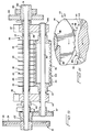
- a feed throat 111 of a strip cutting assembly 113 that includes a first knife roll 114 defined by a plurality of longitudinally spaced circular knives 115 supported on main drive shaft 31, and a feed drum 117 supported on drive shaft 59.
- Each blade 115 is separated from an adjacent knife 115 by an annular spacer ring 119, with knives 115 and rings 119 being carried on an arbor 121 supported on shaft 31.
- Feed drum 117 is provided with an outer circumferential surface 123 which is configured to retard the movement of food product P through throat 111 of assembly 113 for a purpose and in a manner to be later described.
- Strips of food product P exiting strip cutting assembly 113 are conveyed directly to crosscut assembly 47.
- Assembly 47 includes a second knife roll 124 defined by a longitudinal block 125 supported on drive shaft 45 for rotation in the indicated counterclockwise direction.
- a plurality of elongate knives 127 are circumferentially spaced around block 125 for sequential cooperation with a shear edge 129 provided on stripper plate 49. Diced food product DP exiting from crosscut assembly 47 is discharged through chute 17.
- feed roll 67 is supported for rotation on drive shaft 65 which is in turn journalled through a pair of opposed bearings 131 and 133 carried by brackets 71 and 73, respectively.
- the circumferential surface of roll 67 is provided with a plurality of longitudinally spaced peripheral grooves 135. The spacings between grooves 135 correspond to the spacings between circular knives 115 so that edge portions of knives 115 are intermeshed within grooves 135.
- Drive shaft 31 of first knife roll 114 is journalled through a pair of bearings 137 and 139 carried by side frames 35 and 37, respectively.
- Longitudinal block 125 of crosscut assembly 47 is supported for rotation on drive shaft 45, the latter also being journalled through a pair of opposed bearings 141 and 143 carried by side frames 35 and 37, respectively.
- Stripper plate 49 is provided with a plurality of longitudinally spaced slots 145 therein. The spacings between slots 145 also correspond to those of knives 115 so that edge portions of knives 115 are intermeshed within slots 145. As therefore apparent from Fig. 4, knives 115 are intermeshed with feed roll 67 and stripper plate 49 during rotation of drive shafts 31, 45 and 65.
- feed drum 117 of strip cutting assembly 113 is supported for rotation on drive shaft 59, the latter being journalled in a pair of opposed bearings 147 and 149 carried by side frames 35 and 37, respectively.
- the outer circumferential surface 123 of drum 117 is provided with a plurality of longitudinally spaced peripheral grooves 151, the spacings of which also correspond to those of knives 115 so that edge portions of knives 115 are intermeshed within grooves 151.
- knives 115 and feed drum 117 remain intermeshed during rotation about their respective driveshafts 31 and 59.
- main driveshaft 31 is provided with a flanged sleeve 153 for supporting gear 53 and a smaller outer gear 155, the latter being disposed in driving engagement with gear 26 of driven roll 25 for driving feed belt 23 of conveyor assembly 21, as shown in Fig. 1.
- Each circular knife 115 of first knife roll 114 may advantageously be provided with a serrated or scalloped peripheral cutting edge, as shown in Fig. 3.
- a plurality of circular knives 157 having plain cutting edges may also be advantageously utilized, as shown in Fig. 6.
- the choice of cutting edge configuration may be determined in accordance with the nature and consistency of food product P being cut by knife roll 114.
- circumferential surface 123 of feed drum 117 in addition to being provided with peripheral grooves 151, is also configured to define a plurality of longitudinally extending and circumferentially spaced grooves 159.
- Each groove 159 is defined by a radial face 161 and a corresponding tangential face 163.
- faces 161 are directed rearwardly of the direction of food product P travel through feed throat 111 of assembly 113. In this way, faces 161 serve to engage and retard the movement of product P through throat 111 during the cutting thereof, a procedure determined to be highly advantageous during the cutting of fresh meat due to its soft consistency.
- This retarding effect permits knives 115 or 157 to impart the appropriate slicing action on slabs of fresh meat, particularly when rotated at a peripheral speed that is at least twice the peripheral speed of feed drum 117. It is, of course, understood that the described configuration of surface 123 is only preferred and that other configurations are possible so long as such configurations serve the desired function of retarding the movement of food product P through throat 111 of assembly 113.
- Variations in the relative peripheral speeds of feed roll 67, first and second knife rolls 114 and 124, feed drum 117, feed roll 67 and driven roll 25 of conveyor assembly 21 are realized by varying the ratios of the gearing rotating the respective drive shafts through appropriate substitution and replacement of the gears forming pulley and gear assembly 13.
- the degree of spring bias imparted to feed roll 67 by spring loading assembly 79 and vertical position of roll 67 relative to driven roll 25 is established in accordance with the thickness and consistency of food product P and to compensate for occasional oversize pieces of product P moving between feed roll 67 and driven roll 25.
- motor 11 drives pulley and gear assembly 13, thereby imparting rotation in the indicated directions of driven roll 25, feed roll 67, first knife roll 114, feed drum 117 and second knife roll 124 of crosscut assembly 47.
- Product P exiting from between feed roll 67 and drive roll 25 in the direction indicated by arrow A is directly and horizontally transferred to feed throat 111 of strip cutting assembly 113 and is cut into plural strips by first knife roll 114 intermeshed with feed drum 117, the width of the strips corresponding to the spacings between circular knives 115.
- knife roll 114 is rotated by main drive shaft 31 in a clockwise direction, while associated feed drum 117 is rotated in a counterclockwise direction.
- Strips of product P exiting assembly 113 are conveyed to crosscut assembly 47 wherein blades 127 effect transverse cuts of the strips against shear edge 129 of stripper plate 49. This produces diced sections DP of product P, which sections DP are then discharged through chute 17.
- the spring-biased feed roll 67 in combination with the intermeshed disposition of first knife roll 114 within feed roll 67, feed drum 117 and stripper plate 49, collectively contribute to a high speed and reliable dicing of product P by machine 1 in a manner that cannot be duplicated by conventional dicing machines.
- machine 1 renders it particularly advantageous for the dicing of fresh, cooked or frozen tempered slabs of meat.
- pulley and gear assembly 13 is configured so that feed roll 67 will rotate at a peripheral speed that is approximately the same speed as feed belt 23.
- Feed drum 117 of assembly 113 is rotated at approximately the same peripheral speed as meat product P being conveyed by roll 67 and belt 23.
- first knife roll 114 is rotated at a peripheral speed that is at least twice the peripheral speed of feed drum 117. This minimum difference in peripheral speeds was found to produce a continuous slicing action on fresh meat. Since fresh meat has a soft consistency, the rapid rotation of circular knives 115 tends to move meat product P too quickly through assembly 113.
- feed drum 117 is therefore provided with the circumferential surface 123 configuration depicted in Fig. 6 to retard the movement of meat product P being conveyed through feed throat 111 of assembly 113, thus allowing knives 115 to perform the required slicing action on meat product P.
- the cut strips of meat product P are then directed to crosscut assembly 47 for transverse cutting to produce diced sections DP therefrom.
- pulley and gear assembly 13 is adjusted to rotate first knife roll 114 at a peripheral speed that is only slightly faster than the peripheral speed of feed drum 117.
- the smaller variation between the peripheral speeds of blades 115 and drum 117 is possible because cooked or frozen tempered slabs of meat have a harder consistency than fresh meat.
Landscapes
- Life Sciences & Earth Sciences (AREA)
- Forests & Forestry (AREA)
- Engineering & Computer Science (AREA)
- Mechanical Engineering (AREA)
- Crushing And Pulverization Processes (AREA)
- Nonmetal Cutting Devices (AREA)
- Formation And Processing Of Food Products (AREA)
Claims (11)
- Appareil pour découper un produit en morceaux en forme de dés comportant : un ensemble convoyeur (21) pour supporter et convoyer le produit, et un rouleau d'alimentation mobile en rotation (67) placé près d'une extrémité de sortie de l'ensemble convoyeur, le rouleau d'alimentation mobile en rotation (67) étant supporté par un chariot (69) et étant conçu pour venir en prise et convoyer le produit dans un étranglement d'alimentation (111) ; un premier rouleau de couteaux (114) mobile en rotation possédant une pluralité de couteaux circulaires (115), espacés, s'étendant transversalement au trajet d'alimentation de produit, pour découper le produit en une pluralité de bandes ; un tambour d'alimentation mobile en rotation (117) s'étendant globalement parallèlement au premier rouleau de couteaux (114) et définissant avec celui-ci un étranglement d'alimentation (111), le tambour d'alimentation mobile en rotation (117) possédant une pluralité de rainures périphériques (151) espacées longitudinalement ; un ensemble de découpe transversale (47) comprenant un second rouleau de couteaux (124) possédant une pluralité de couteaux allongés (127) s'étendant globalement transversalement au trajet d'alimentation de produit ; une plaque de séparation (49) définissant un bord de cisaillement (129), la plaque de séparation (49) étant associée fonctionnellement avec le premier rouleau de couteaux (114) pour retirer le produit d'entre les couteaux (115) espacés, après que le produit a été découpé en une pluralité de bandes et un bord de cisaillement (129) associé fonctionnellement avec le second rouleau de couteaux (124) de telle manière que les couteaux allongés (127) coopèrent avec le bord de cisaillement (129) pour découper le produit en des morceaux en forme de dés, la plaque de séparation (49) comportant une pluralité de fentes espacées (145) ; et un moyen d'entraînement (11, 13, 33) associé de manière fonctionnelle avec le premier rouleau de couteaux (114), le tambour d'alimentation (117), le rouleau d'alimentation (67), et le second rouleau de couteaux (124) de manière à entraîner en rotation le premier rouleau de couteaux (114), le tambour d'alimentation (117), le rouleau d'alimentation (67) et le second rouleau de couteaux (124), caractérisé en ce que l'ensemble convoyeur (21) comprend : une courroie d'alimentation (23) entraînée, globalement horizontale, pour supporter et convoyer le produit, ce par quoi le rouleau d'alimentation (67) est placé près d'une extrémité de la courroie d'alimentation (23) ; un chariot (69) supportant le rouleau d'alimentation (67) pour un déplacement vertical ; et un moyen de rappel (91) associé de façon fonctionnelle avec le rouleau d'alimentation (67) pour rappeler de manière élastique le rouleau d'alimentation (67) contre le produit, sur la courroie d'alimentation (23) ; et en ce que le tambour d'alimentation rotatif (117), ayant ladite surface périphérique, définit une pluralité de rainures (159), espacées le long de la circonférence, s'étendant globalement transversalement au trajet d'alimentation de produit (111), conçues pour contacter le produit de manière à retarder le déplacement du produit dans l'étranglement d'alimentation (111).
- Appareil selon la revendication 1, caractérisé en ce que les rainures longitudinales (159) dans le tambour d'alimentation (117), sont chacune définies par une face globalement radiale (161) et une face globalement tangentielle (163).
- Appareil selon la revendication 2, caractérisé en ce que la face globalement radiale (161) est tournée dans un sens globalement opposé au sens de rotation du tambour d'alimentation (117).
- Appareil selon l'une quelconque des revendications précédentes, caractérisé en ce que le moyen d'entraînement (11, 13, 33) entraîne en rotation le premier rouleau de couteaux (114) et le tambour d'alimentation (117) dans des sens contraires.
- Appareil selon l'une quelconque des revendications précédentes, caractérisé en ce que le moyen d'entraînement (11, 13, 33) entraîne en rotation le premier rouleau de couteaux (114) à une vitesse périphérique d'au moins environ deux fois la vitesse périphérique du tambour d'alimentation (117).
- Appareil selon l'une quelconque des revendications précédentes, caractérisé en ce que chacun des couteaux (115) globalement circulaires présente un bord de coupe dentelé.
- Appareil selon l'une quelconque des revendications précédentes, caractérisé en ce que le moyen de rappel comprend un moyen formant ressort (91) associé de manière fonctionnelle avec le rouleau d'alimentation (67).
- Appareil selon la revendication 7, caractérisé par un moyen (99) pour régler la force de rappel du moyen formant ressort (91).
- Appareil selon l'une quelconque des revendications précédentes, caractérisé en ce que l'ensemble convoyeur (21) comprend un rouleau entraîné (25) et un rouleau fou (27) pour entraîner la courroie d'alimentation (23), le rouleau entraîné (25) étant placé à une extrémité de sortie de la courroie d'alimentation (23), sensiblement au-dessous de la courroie d'alimentation (67).
- Procédé de découpe d'un produit en une pluralité de morceaux en forme de dés en utilisant l'appareil de la revendication 1 caractérisé par les étapes de :
convoyage du produit suivant un trajet d'alimentation en produit par un ensemble convoyeur (21) incluant une courroie d'alimentation (23), entraînée, globalement horizontale, ayant une extrémité de sortie et un rouleau d'alimentation mobile en rotation (67) placé près de l'extrémité de sortie de la courroie d'alimentation (23) pour venir en prise avec le produit ;
rappel du rouleau d'alimentation (67) contre le produit sur la courroie d'alimentation (23) ;
découpe du produit en une pluralité de bandes en le faisant passer directement à partir de l'ensemble convoyeur (23) et du rouleau d'alimentation (67) dans un étranglement d'alimentation (111), défini par un premier rouleau de couteaux (114) mobile en rotation comportant une pluralité de couteaux globalement circulaires (115), espacés, s'étendant transversalement au trajet d'alimentation de produit, et un tambour d'alimentation mobile en rotation (117) s'étendant globalement parallèlement au premier rouleau de couteaux (114) et ayant une surface périphérique définissant un pluralité de rainures longitudinales (159) s'étendant globalement transversalement au trajet d'alimentation de produit, de manière à contacter le produit de façon à commander la vitesse du produit dans l'étranglement d'alimentation (111) ;
utilisation d'une plaque de séparation (49) définissant un cisaillement (129) en association fonctionnelle avec le premier rouleau de couteaux (114) pour retirer les bandes de produit d'entre les couteaux espacés (115) ;
utilisation d'un ensemble de découpe transversale (47), possédant un second rouleau de couteaux (124) avec une pluralité de couteaux allongés (127) s'étendant globalement transversalement au trajet d'alimentation de produit et coopérant avec le bord de cisaillement (129) pour couper les bandes de produits en une pluralité de morceaux en forme de dés ; et
utilisation d'un moyen d'entraînement (11, 13, 33) pour entraîner en rotation le premier rouleau de couteaux (114), le rouleau d'alimentation (67), le tambour d'alimentation (117) et le second rouleau de couteaux (124). - Procédé selon la revendication 10, caractérisé par l'étape d'entraînement en rotation du rouleau de couteaux (114) à une vitesse périphérique qui est au moins environ deux fois la vitesse périphérique du tambour d'alimentation (117).
Applications Claiming Priority (2)
| Application Number | Priority Date | Filing Date | Title |
|---|---|---|---|
| US25484388A | 1988-10-07 | 1988-10-07 | |
| US254843 | 1988-10-07 |
Publications (3)
| Publication Number | Publication Date |
|---|---|
| EP0363220A2 EP0363220A2 (fr) | 1990-04-11 |
| EP0363220A3 EP0363220A3 (fr) | 1991-01-23 |
| EP0363220B1 true EP0363220B1 (fr) | 1993-08-11 |
Family
ID=22965799
Family Applications (1)
| Application Number | Title | Priority Date | Filing Date |
|---|---|---|---|
| EP19890310260 Expired - Lifetime EP0363220B1 (fr) | 1988-10-07 | 1989-10-06 | Appareil pour couper en cubes |
Country Status (4)
| Country | Link |
|---|---|
| EP (1) | EP0363220B1 (fr) |
| JP (1) | JPH02152793A (fr) |
| CA (1) | CA1318574C (fr) |
| DE (1) | DE68908328T2 (fr) |
Cited By (1)
| Publication number | Priority date | Publication date | Assignee | Title |
|---|---|---|---|---|
| DE19529613A1 (de) * | 1994-08-17 | 1996-02-22 | Pallmann Kg Maschf | Zerkleinerungsvorrichtung für schneidbare Stoffe zur Erzeugung prismatischer, insbesondere kubischer Partikel |
Families Citing this family (9)
| Publication number | Priority date | Publication date | Assignee | Title |
|---|---|---|---|---|
| GB2292880B (en) * | 1994-08-17 | 1996-12-04 | Pallmann Kg Maschf | Size reduction apparatus for the production of prismatical and particularly cubical particles from cuttable materials. |
| DE102007063295A1 (de) * | 2007-12-27 | 2009-07-02 | Natec Gmbh | Schneiden einer weichen Lebensmittelmasse |
| RO129769B1 (ro) * | 2013-03-12 | 2018-07-30 | Petru Tompea | Maşină şi metodă de tăiat carne în cuburi |
| US9855669B2 (en) * | 2014-03-13 | 2018-01-02 | Urschel Laboratories, Inc. | Dicing machines and methods of use |
| MX2019014918A (es) | 2017-06-14 | 2020-02-07 | Urschel Laboratories Inc | Maquina de reduccion de tamaño y unidad de reduccion de tamaño para la misma. |
| CN109176663A (zh) * | 2018-10-11 | 2019-01-11 | 漯河恒丰机械制造科技有限公司 | 食品切花机分段切断机构 |
| CN112792893A (zh) * | 2021-02-03 | 2021-05-14 | 黄冈市农业科学院 | 一种食用菌纵向切片机 |
| CN113092217B (zh) * | 2021-05-10 | 2024-07-02 | 济源市畜产品质量监测检验中心 | 畜产品检测样品处理装置 |
| CN113561242B (zh) * | 2021-07-01 | 2022-06-24 | 湖南炬神电子有限公司 | 一种新型自动分板机 |
Family Cites Families (5)
| Publication number | Priority date | Publication date | Assignee | Title |
|---|---|---|---|---|
| US2011475A (en) * | 1929-10-07 | 1935-08-13 | Micro Corp | Bread slicing machine |
| US2060540A (en) * | 1933-04-03 | 1936-11-10 | Ind Patents Corp | Slicing machine attachment |
| US2506985A (en) * | 1947-11-18 | 1950-05-09 | Herald P Arnt | Slicing machine, including spaced disk cutters and rotary feeder |
| US2603262A (en) * | 1948-01-29 | 1952-07-15 | William E Urschel | Sectionalizing cutting machine |
| US3826185A (en) * | 1972-03-09 | 1974-07-30 | Castle & Cooke | Pineapple recoring, segmenting and chunking |
-
1989
- 1989-09-15 CA CA000611619A patent/CA1318574C/fr not_active Expired - Lifetime
- 1989-10-06 JP JP26193489A patent/JPH02152793A/ja active Pending
- 1989-10-06 DE DE1989608328 patent/DE68908328T2/de not_active Expired - Lifetime
- 1989-10-06 EP EP19890310260 patent/EP0363220B1/fr not_active Expired - Lifetime
Cited By (2)
| Publication number | Priority date | Publication date | Assignee | Title |
|---|---|---|---|---|
| DE19529613A1 (de) * | 1994-08-17 | 1996-02-22 | Pallmann Kg Maschf | Zerkleinerungsvorrichtung für schneidbare Stoffe zur Erzeugung prismatischer, insbesondere kubischer Partikel |
| DE19529613C2 (de) * | 1994-08-17 | 1998-01-22 | Pallmann Kg Maschf | Zerkleinerungsvorrichtung für schneidbare Stoffe zur Erzeugung prismatischer, insbesondere kubischer Partikel |
Also Published As
| Publication number | Publication date |
|---|---|
| DE68908328T2 (de) | 1994-02-10 |
| EP0363220A3 (fr) | 1991-01-23 |
| CA1318574C (fr) | 1993-06-01 |
| DE68908328D1 (en) | 1993-09-16 |
| EP0363220A2 (fr) | 1990-04-11 |
| JPH02152793A (ja) | 1990-06-12 |
Similar Documents
| Publication | Publication Date | Title |
|---|---|---|
| US5129299A (en) | Dicing machine | |
| EP0759837B1 (fr) | Lame de coupe pour appareil rotatif pour couper un produit alimentaire et appareil rotatif de coupe | |
| CA3066248C (fr) | Machine de reduction de taille et unite de reduction de taille associee | |
| US7100486B2 (en) | Apparatus for dicing a deformable product | |
| EP0363220B1 (fr) | Appareil pour couper en cubes | |
| CA3041296C (fr) | Machines de reduction de taille, unites d'alimentation associees et procedes d'utilisation | |
| US3972256A (en) | Meat slicer | |
| EP0791293B1 (fr) | Procédé et appareil pour couper et déporer la pâte | |
| US5044240A (en) | Apparatus for conveying and cutting a product into discrete pieces | |
| US3195594A (en) | Material cutting machine | |
| EP1268142B1 (fr) | Machine de decoupage destinee a des articles de materiaux du type en bande equipee d'une zone d'affutage des lames laquelle est separee de la zone de decoupage | |
| US5673863A (en) | Size reduction apparatus for the production of prismatical and particularly cubical particles from cuttable materials | |
| US3654978A (en) | Powered cutter apparatus | |
| FI72895C (fi) | Foerfarande och anordning foer disintegrering av material. | |
| US3678976A (en) | Onion peeling apparatus | |
| US4960021A (en) | Meat slicer | |
| GB2139080A (en) | Slicing apparatus for bakery products | |
| GB1370380A (en) | Apparatus and method for handling a process cheese spread and cutting it into slices | |
| US3550658A (en) | Nut-kernel dicing machine | |
| US3799050A (en) | Pineapple chunking apparatus | |
| JPS6348676B2 (fr) | ||
| EP0353446B1 (fr) | Dispositif pour couper en longueurs des pièces alimentaires | |
| GB2037224A (en) | Apparatus for portioning meat | |
| GB2098463A (en) | Apparatus for cutting foodstuffs | |
| IE49830B1 (en) | Apparatus for portioning meat |
Legal Events
| Date | Code | Title | Description |
|---|---|---|---|
| PUAI | Public reference made under article 153(3) epc to a published international application that has entered the european phase |
Free format text: ORIGINAL CODE: 0009012 |
|
| AK | Designated contracting states |
Kind code of ref document: A2 Designated state(s): BE CH DE FR GB IT LI NL SE |
|
| PUAL | Search report despatched |
Free format text: ORIGINAL CODE: 0009013 |
|
| AK | Designated contracting states |
Kind code of ref document: A3 Designated state(s): BE CH DE FR GB IT LI NL SE |
|
| 17P | Request for examination filed |
Effective date: 19910703 |
|
| 17Q | First examination report despatched |
Effective date: 19920626 |
|
| ITF | It: translation for a ep patent filed | ||
| GRAA | (expected) grant |
Free format text: ORIGINAL CODE: 0009210 |
|
| AK | Designated contracting states |
Kind code of ref document: B1 Designated state(s): BE CH DE FR GB IT LI NL SE |
|
| REF | Corresponds to: |
Ref document number: 68908328 Country of ref document: DE Date of ref document: 19930916 |
|
| ET | Fr: translation filed | ||
| PLBE | No opposition filed within time limit |
Free format text: ORIGINAL CODE: 0009261 |
|
| STAA | Information on the status of an ep patent application or granted ep patent |
Free format text: STATUS: NO OPPOSITION FILED WITHIN TIME LIMIT |
|
| 26N | No opposition filed | ||
| EAL | Se: european patent in force in sweden |
Ref document number: 89310260.8 |
|
| PGFP | Annual fee paid to national office [announced via postgrant information from national office to epo] |
Ref country code: SE Payment date: 19960919 Year of fee payment: 8 |
|
| PGFP | Annual fee paid to national office [announced via postgrant information from national office to epo] |
Ref country code: NL Payment date: 19960924 Year of fee payment: 8 |
|
| PGFP | Annual fee paid to national office [announced via postgrant information from national office to epo] |
Ref country code: CH Payment date: 19970115 Year of fee payment: 8 |
|
| PG25 | Lapsed in a contracting state [announced via postgrant information from national office to epo] |
Ref country code: SE Free format text: LAPSE BECAUSE OF NON-PAYMENT OF DUE FEES Effective date: 19971007 |
|
| PG25 | Lapsed in a contracting state [announced via postgrant information from national office to epo] |
Ref country code: LI Free format text: LAPSE BECAUSE OF NON-PAYMENT OF DUE FEES Effective date: 19971031 Ref country code: CH Free format text: LAPSE BECAUSE OF NON-PAYMENT OF DUE FEES Effective date: 19971031 |
|
| PG25 | Lapsed in a contracting state [announced via postgrant information from national office to epo] |
Ref country code: NL Free format text: LAPSE BECAUSE OF NON-PAYMENT OF DUE FEES Effective date: 19980501 |
|
| REG | Reference to a national code |
Ref country code: CH Ref legal event code: PL |
|
| NLV4 | Nl: lapsed or anulled due to non-payment of the annual fee |
Effective date: 19980501 |
|
| EUG | Se: european patent has lapsed |
Ref document number: 89310260.8 |
|
| REG | Reference to a national code |
Ref country code: GB Ref legal event code: IF02 |
|
| PG25 | Lapsed in a contracting state [announced via postgrant information from national office to epo] |
Ref country code: IT Free format text: LAPSE BECAUSE OF NON-PAYMENT OF DUE FEES;WARNING: LAPSES OF ITALIAN PATENTS WITH EFFECTIVE DATE BEFORE 2007 MAY HAVE OCCURRED AT ANY TIME BEFORE 2007. THE CORRECT EFFECTIVE DATE MAY BE DIFFERENT FROM THE ONE RECORDED. Effective date: 20051006 |
|
| PGFP | Annual fee paid to national office [announced via postgrant information from national office to epo] |
Ref country code: GB Payment date: 20080915 Year of fee payment: 20 |
|
| PGFP | Annual fee paid to national office [announced via postgrant information from national office to epo] |
Ref country code: DE Payment date: 20081031 Year of fee payment: 20 |
|
| PGFP | Annual fee paid to national office [announced via postgrant information from national office to epo] |
Ref country code: BE Payment date: 20081031 Year of fee payment: 20 |
|
| PGFP | Annual fee paid to national office [announced via postgrant information from national office to epo] |
Ref country code: FR Payment date: 20081006 Year of fee payment: 20 |
|
| REG | Reference to a national code |
Ref country code: GB Ref legal event code: PE20 Expiry date: 20091005 |
|
| BE20 | Be: patent expired |
Owner name: *URSCHEL LABORATORIES INC. Effective date: 20091006 |
|
| PG25 | Lapsed in a contracting state [announced via postgrant information from national office to epo] |
Ref country code: GB Free format text: LAPSE BECAUSE OF EXPIRATION OF PROTECTION Effective date: 20091005 |