EP0361997A1 - Auflegegerät zum automatischen Auflegen einer Fasermatte auf eine Form - Google Patents
Auflegegerät zum automatischen Auflegen einer Fasermatte auf eine Form Download PDFInfo
- Publication number
- EP0361997A1 EP0361997A1 EP89402324A EP89402324A EP0361997A1 EP 0361997 A1 EP0361997 A1 EP 0361997A1 EP 89402324 A EP89402324 A EP 89402324A EP 89402324 A EP89402324 A EP 89402324A EP 0361997 A1 EP0361997 A1 EP 0361997A1
- Authority
- EP
- European Patent Office
- Prior art keywords
- head
- roller
- main support
- axis
- articulation
- Prior art date
- Legal status (The legal status is an assumption and is not a legal conclusion. Google has not performed a legal analysis and makes no representation as to the accuracy of the status listed.)
- Granted
Links
- 239000000835 fiber Substances 0.000 title claims abstract description 20
- 239000007787 solid Substances 0.000 claims abstract description 3
- 239000011248 coating agent Substances 0.000 claims description 26
- 238000000576 coating method Methods 0.000 claims description 26
- 239000002131 composite material Substances 0.000 claims description 15
- 230000001681 protective effect Effects 0.000 claims description 12
- 238000006073 displacement reaction Methods 0.000 claims description 10
- 238000005452 bending Methods 0.000 claims description 8
- 230000003321 amplification Effects 0.000 claims description 5
- 230000006835 compression Effects 0.000 claims description 5
- 238000007906 compression Methods 0.000 claims description 5
- 238000003199 nucleic acid amplification method Methods 0.000 claims description 5
- 239000000463 material Substances 0.000 claims description 4
- 238000011144 upstream manufacturing Methods 0.000 claims description 3
- 230000003044 adaptive effect Effects 0.000 description 7
- 238000009826 distribution Methods 0.000 description 4
- 238000000034 method Methods 0.000 description 3
- 230000008901 benefit Effects 0.000 description 2
- 238000010276 construction Methods 0.000 description 2
- 230000001627 detrimental effect Effects 0.000 description 2
- 238000004519 manufacturing process Methods 0.000 description 2
- 230000010355 oscillation Effects 0.000 description 2
- JOYRKODLDBILNP-UHFFFAOYSA-N Ethyl urethane Chemical compound CCOC(N)=O JOYRKODLDBILNP-UHFFFAOYSA-N 0.000 description 1
- 229910000831 Steel Inorganic materials 0.000 description 1
- 230000009471 action Effects 0.000 description 1
- 230000006978 adaptation Effects 0.000 description 1
- 230000001413 cellular effect Effects 0.000 description 1
- 230000001276 controlling effect Effects 0.000 description 1
- 238000005520 cutting process Methods 0.000 description 1
- 230000001419 dependent effect Effects 0.000 description 1
- 238000000151 deposition Methods 0.000 description 1
- 230000000694 effects Effects 0.000 description 1
- 239000003822 epoxy resin Substances 0.000 description 1
- 238000005470 impregnation Methods 0.000 description 1
- 238000003475 lamination Methods 0.000 description 1
- 210000000056 organ Anatomy 0.000 description 1
- 239000004033 plastic Substances 0.000 description 1
- 239000002985 plastic film Substances 0.000 description 1
- 229920006255 plastic film Polymers 0.000 description 1
- 229920000647 polyepoxide Polymers 0.000 description 1
- 230000008569 process Effects 0.000 description 1
- 230000009467 reduction Effects 0.000 description 1
- 230000001105 regulatory effect Effects 0.000 description 1
- 230000004044 response Effects 0.000 description 1
- 238000007493 shaping process Methods 0.000 description 1
- 239000010959 steel Substances 0.000 description 1
- 238000013517 stratification Methods 0.000 description 1
- 239000000126 substance Substances 0.000 description 1
Images
Classifications
-
- B—PERFORMING OPERATIONS; TRANSPORTING
- B29—WORKING OF PLASTICS; WORKING OF SUBSTANCES IN A PLASTIC STATE IN GENERAL
- B29C—SHAPING OR JOINING OF PLASTICS; SHAPING OF MATERIAL IN A PLASTIC STATE, NOT OTHERWISE PROVIDED FOR; AFTER-TREATMENT OF THE SHAPED PRODUCTS, e.g. REPAIRING
- B29C70/00—Shaping composites, i.e. plastics material comprising reinforcements, fillers or preformed parts, e.g. inserts
- B29C70/04—Shaping composites, i.e. plastics material comprising reinforcements, fillers or preformed parts, e.g. inserts comprising reinforcements only, e.g. self-reinforcing plastics
- B29C70/28—Shaping operations therefor
- B29C70/30—Shaping by lay-up, i.e. applying fibres, tape or broadsheet on a mould, former or core; Shaping by spray-up, i.e. spraying of fibres on a mould, former or core
- B29C70/38—Automated lay-up, e.g. using robots, laying filaments according to predetermined patterns
- B29C70/386—Automated tape laying [ATL]
- B29C70/388—Tape placement heads, e.g. component parts, details or accessories
-
- Y—GENERAL TAGGING OF NEW TECHNOLOGICAL DEVELOPMENTS; GENERAL TAGGING OF CROSS-SECTIONAL TECHNOLOGIES SPANNING OVER SEVERAL SECTIONS OF THE IPC; TECHNICAL SUBJECTS COVERED BY FORMER USPC CROSS-REFERENCE ART COLLECTIONS [XRACs] AND DIGESTS
- Y10—TECHNICAL SUBJECTS COVERED BY FORMER USPC
- Y10T—TECHNICAL SUBJECTS COVERED BY FORMER US CLASSIFICATION
- Y10T156/00—Adhesive bonding and miscellaneous chemical manufacture
- Y10T156/12—Surface bonding means and/or assembly means with cutting, punching, piercing, severing or tearing
- Y10T156/1348—Work traversing type
-
- Y—GENERAL TAGGING OF NEW TECHNOLOGICAL DEVELOPMENTS; GENERAL TAGGING OF CROSS-SECTIONAL TECHNOLOGIES SPANNING OVER SEVERAL SECTIONS OF THE IPC; TECHNICAL SUBJECTS COVERED BY FORMER USPC CROSS-REFERENCE ART COLLECTIONS [XRACs] AND DIGESTS
- Y10—TECHNICAL SUBJECTS COVERED BY FORMER USPC
- Y10T—TECHNICAL SUBJECTS COVERED BY FORMER US CLASSIFICATION
- Y10T156/00—Adhesive bonding and miscellaneous chemical manufacture
- Y10T156/17—Surface bonding means and/or assemblymeans with work feeding or handling means
- Y10T156/1788—Work traversing type and/or means applying work to wall or static structure
Definitions
- the invention relates to the automatic placement, on a mold, of a sheet of fibers for the manufacture of various parts such as aircraft wings, for example from a composite ribbon made up of glued fiber elements. (for example by impregnation of epoxy resin) which are precut to the desired shape and dimensions and which are held between two protective films until the place of their application on the mold.
- the upper film is formed by a paper tape of suitable mechanical and chemical characteristics, while the lower film is constituted by a very thin plastic film.
- the composite tape thus formed often having a width of between 25 and 150 mm and a length of around 250 m, is in the form of a reel carried by an orientable part known as a "topping head".
- the technique consists in depositing, on the mold, with the greatest possible precision, the fiber elements (already cut and impregnated) conveyed in the form of the aforementioned composite tape.
- Current machines for this purpose are equipped with a member, such as a roller or a shoe for applying the fiber ribbon to the mold, the upper strip of paper being recovered after it has passed under the application roller. , the lower protective film having been removed before the fibers were applied against the mold.
- the topping head which supports in particular the reel of composite tape, the reels for recovering protective films and the applicator device, is carried by a structure, for example analogous to a gantry, making it possible to move the topping head, in translation , along a longitudinal axis X (or axis of advance), a transverse axis Y and a vertical axis Z, as well as in rotation about the axis Z and around a horizontal axis oriented according to the advance of the machine .
- a structure for example analogous to a gantry
- the topping head and therefore the tape applicator device, can thus be positioned and oriented, generally under the control of a numerical control, to deposit the composite tape according to the chosen profile.
- the object of the present invention is to remedy this drawback by incorporating a joint, along a horizontal axis, on the support of the tape application member, so that the orientation of this member is instantly adapts to profile variations encountered, without presenting the drawbacks of known joints.
- the present invention relates to a lapping device, for the automatic placement of a sheet of fibers on a mold, which comprises a topping head adapted to move, under the control of a numerical control, in following translation three axes X, Y, Z and, in rotation, around the vertical axis Z as well as around a horizontal axis oriented along the advance of the machine, said coating head carrying an applicator member of the fiber web to be deposited on the surface to be coated, said applicator member being mounted on a support which is connected to the lapping by an articulation around a horizontal axis, the articulation being interposed between an auxiliary support, supporting the applicator member and a main support carried by the lapping head, characterized in that the articulation is a deformable articulation without play with very slight flexibility.
- such a deformable articulation without play, advantageously consists of a solid part reserved between two slots formed between the main support and the auxiliary support.
- the aforementioned flexible articulation has only limited freedom of flexion, of a few degrees, for example 2 degrees and only provides an "adaptation" of the orientation of the applicator member along an axis of oscillation which can be designated under the name of auxiliary axis, with respect to the "main" axis of rotation of the lapping head, around the aforementioned horizontal axis, the rotations around this "main” axis being controlled by digital control in a conventional manner.
- this flexible joint could be passive and it would simply allow the applicator member to orient itself normally on the surface.
- the application pressures of the applicator member on the strip of composite material are not distributed equitably over the entire width of the strip.
- the articula Flexible tion is used in active form, that is to say that any flexion of the joint is detected by a sensor which delivers a signal.
- this signal controls, by means of the machine's digital control, a rotation of the coating head, along the main axis of rotation, in the desired direction to regain the equitable distribution of pressures over the entire width.
- the band Of the band.
- the applicator member is advantageously a roller.
- the roller has a double flexibility and comprises an axis which is deformable in bending, providing general flexibility, said axis being surrounded by a volume of flexible material which is deformable in local compression.
- the roller advantageously has a curved outer surface, either convex in a barrel, or concave in a diabolo.
- the device comprises means for separating two protective strips from the strip of impregnated fibers arranged upstream of the applicator roller.
- a displacement sensor When the movements of the coating head are controlled by a digital control, it is advantageous for a displacement sensor to be interposed between the auxiliary support and the main support; that the signals supplied by this sensor are transmitted, after amplification by an amplifier, to the digital control in order to adapt the instructions contained in the digital control and rotate the topping head in the direction canceling the bending of the flexible joint.
- the main support is mounted vertically movable on the topping head; pneumatic springs or cylinders interposed between the main support and the coating head tend to exert a contact pressure of the applicator member on the surface to be coated; a displacement sensor is interposed between the coating head and the main support; the signals supplied by this sensor are transmitted, after amplification by an amplifier, to the digital control to raise or lower, according to the normal to the surface to be coated, the topping head and maintain the deflection of the main support at a determined value.
- the main support comprises arms mounted in rotation about an axis and guide means centered on the axis are provided to guide the composite strip supplied and the protective strips in return.
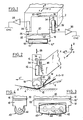
- topping head 2 for applying a strip of composite material 4 on the surface of a mold 6, for example for the manufacture of part of an aircraft.
- the topping head 2 is carried by a structure (not shown) so as to move in translation along the three axes X, Y, Z and, in rotation, around the vertical axis Z and around a horizontal axis oriented along the advance of the machine.
- the movements of the coating head are controlled by a digital control (not shown) so as to follow the profile of the surface 6 to be coated.
- the strip of composite material 4 + 8 + 12 is unwound from a supply reel (not shown), is stripped of a lower protective strip 8, and is then stripped of the upper protective strip 12 and is then applied to the surface 6 by an applicator member such as a roller 10.
- the upper protective strip 12 (generally made of paper) is separated from the composite strip immediately before passing under the applicator member (roller 10), so that only the strip of prepreg fibers is in contact with the roller at the point of contact with the surface to be coated.
- the roller 10 is preferable to an applicator shoe, because even if the strip of fibers stripped of its protective strip sticks to it, it can rotate and allow the application.
- the different bodies of the coating device are carried by a main support or carriage 16 which can be rigidly linked to the coating head 2 but is preferably, as will be seen below, mounted vertically movable on the topping head by sliding, in the manner of a carriage, or else by means of an articulated arm.
- the applicator member 10 such as a roller
- an auxiliary support 18 which is connected to the main support 16 by a flexible deformable articulation 20, the flexibility of this articulation being around an axis.
- horizontal X ′ (FIG. 2) oriented in the direction of advance of the machine and located equidistant from the edges 10′-10 ⁇ of the roller 10.
- the deformable joint 20 is only very slightly flexible (for example 2 degrees) and it only has an adaptive function, as will be seen in the following.
- the articulation 20 can be simply produced, as shown in FIG. 1, by cutting two slots 22-22 ′ between the main support 16 and the auxiliary support 18, but another form of flexible deformable articulation without play, could be used, as long as the low flexibility is provided only around the axis X ′ and that the connection is clear and rigid around the other axes.
- the articulation 20 is located, in the vertical direction, as close as possible to the roller 10 or equivalent applicator member. Thanks to the flexibility of the joint, the applicator member can normally bear, over its entire width, against the surface to be coated.
- a displacement sensor 24 is fixed to the main support 16, its detector member 26 being in contact with the auxiliary support 18 (FIG. 1).
- a displacement signal is then delivered by the sensor 24.
- This signal is amplified by an amplifier 28 and is sent to CNC numerical control, which controls a rotation of the coating head 2, around the horizontal axis, in the appropriate direction to find an equitable distribution of pressures over the entire width of the deposited strip, which improves the quality of the coating .
- This function of the flexible joint is therefore an adaptive function which is superimposed on the conventional function of digital control.
- this function has the advantage that the coating head is brought back (by the rotation described above) in a symmetrical position relative to the auxiliary support 18.
- This is an important advantage, because several organs (for example the supply coils and the receiving coils as well as the guide rollers of the composite strip) are carried either by the main support 16 or by the head 2 itself and the good is thus preserved alignment between these various members and the applicator roller. This avoids “drifts” or “misalignment” of the tape which are detrimental to the quality of the coating.
- the device according to the invention preferably further comprises an automatic axial adaptive system for regulating the pressure for applying the composite strip.
- the main support 16 is mounted, not rigidly on the topping head 2, but with a freedom of movement normal to the surface to be coated limited (see arrow 29 in FIG. 2), for example at by means of slides (not shown), in the manner of a machine tool carriage.
- One or more springs or pneumatic cylinders 30 tend to lower the support carriage 16 relative to the lay-up head 2 and to exert an application pressure of the roller 10 on the strip 4 to be deposited.
- a displacement sensor 32 is fixed to the covering head 2 while its movable member 34 bears against a stop 36 integral with the support carriage 16.
- the signal supplied by the sensor 32 is amplified by an amplifier 38 and transmitted to the digital control CNC ( Figure 1) so as to superimpose the orders issued by it and to maintain the sensor in the central position by raising or lowering the coating head according to the normal to the surface to be coated.
- the adaptivity function both in rotation and in application pressure regulation, can be selected or not by an auxiliary function of the digital control.
- the adaptive control is selected or not by the program. If it is not selected, the rotation of the head is controlled by the numerical control of a conventional material. If selected, then it is locked until the roller touches the workpiece. The movement then obeys the information delivered by the digital control as above. After contact, the adaptive function is unlocked and the movement of the head is that controlled by the digital control plus that controlled by the signal delivered by the sensor 24. This option makes it possible to keep the head normal to the surface even if it is is roughly defined or if this surface is modified by the tablecloths already deposited.
- the axial adaptive function is controlled by the sensor 32 and the amplifier 38. Its operation is analogous to that of the rotary control. Its action is to raise and lower the head normally to the surface to be coated as a function of the signal delivered by the sensor 32 and amplified by the amplifier 38.
- the control conditions are the same as above.
- a roller can be used as the applicator member, as shown in FIGS. 1 and 2.
- an applicator roller 40 such as that shown in FIGS. 3 and 4 is preferably used and the construction of which is such that it has double flexibility, one in general bending, the other in local compression.
- the roller 40 is mounted on an axis 42 carried by the auxiliary support 18 of the topping head, this axis being produced for example from steel or composite fibers and being deformable in bending to ensure the general bending function of the roller.
- the volume 44 of the roller is made of flexible material (for example urethane, rubber, cellular plastic) which can deform under local compression.
- flexible material for example urethane, rubber, cellular plastic
- empty cavities 46 in the volume 44 of the roller Preferably, the outer surface of the roller has a shape adapted to the surface to be coated, for example a barrel shape (see FIG. 3) for a concave surface, or a diabolo shape for a convex surface.
- the overall flexibility of a roller thus produced is such that the local pressure on the fibers is low, which eliminates the "wave” effect often encountered with the applicator rollers used until now and makes it possible to obtain, in combination with the adaptive system described in the above, high-quality laminated structures, especially for the aeronautical industry.
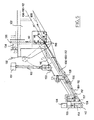
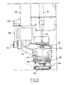
- FIGS. 5 and 6 show a preferred embodiment of the invention.
- the applicator roller 110 is mounted on the head 102 by means of two applicator arms 116, roller supports. These arms 116 are pivotally mounted around an axis 150 and are controlled by a pneumatic cylinder 151 whose body is articulated to the head 102 and whose rod 152 is articulated on a plate 153 connecting the two arms.
- the roller 110 pivots in the branches of a stirrup 154 connected by the deformable articulation 120 to the support 155 secured to the arms 116.
- the deformable articulation allows a very slight inclination of the order of 1 / 10th of mm by 50 mm.
- the sensor 124 makes it possible to measure the displacement, or better the forces exerted on the roller 110.
- the assembly 104 + 112 continues to a second roller 157, located just upstream of the applicator roller 110, and making it possible to extract the paper 112, which allows the only bare strip 104 of prepreg fibers to pass through the roller 110.
- guide rollers 158 pinch, on the one hand, the assembly 104 + 108 + 112 supplied, on the other hand, the strips 108 and 112 in return, so to guarantee the consistency of the strip lengths whatever the deflection of the applicator arms 116.
- the normal displacement at the application surface of the arm, or the application force of the arm, is measured by means of a displacement sensor 132, the rod 134 of which rests on a bar 136 integral in rotation with the arms 116.
- sensors 136 and 124 are analogous to what has already been explained on the occasion of FIGS. 1 and 2.
- the numerical control is provided for memorizing and calculating the three geometric coordinates of each point on the surface, and also the three geometric components of the vector normal to the surface at said point, so as to be able to control the disengagement movement of the applicator roller normally. on the surface, which avoids involuntary dragging of the applied strip and therefore positioning errors.
Landscapes
- Engineering & Computer Science (AREA)
- Robotics (AREA)
- Chemical & Material Sciences (AREA)
- Composite Materials (AREA)
- Mechanical Engineering (AREA)
- Moulding By Coating Moulds (AREA)
- Application Of Or Painting With Fluid Materials (AREA)
- Coating Apparatus (AREA)
Applications Claiming Priority (2)
| Application Number | Priority Date | Filing Date | Title |
|---|---|---|---|
| FR8811244 | 1988-08-26 | ||
| FR8811244A FR2635714B1 (fr) | 1988-08-26 | 1988-08-26 | Dispositif de nappage pour la mise en place automatique d'une nappe de fibres sur un moule et machine comportant un tel dispositif |
Publications (2)
| Publication Number | Publication Date |
|---|---|
| EP0361997A1 true EP0361997A1 (de) | 1990-04-04 |
| EP0361997B1 EP0361997B1 (de) | 1992-01-15 |
Family
ID=9369528
Family Applications (1)
| Application Number | Title | Priority Date | Filing Date |
|---|---|---|---|
| EP89402324A Expired - Lifetime EP0361997B1 (de) | 1988-08-26 | 1989-08-23 | Auflegegerät zum automatischen Auflegen einer Fasermatte auf eine Form |
Country Status (6)
| Country | Link |
|---|---|
| US (1) | US5074948A (de) |
| EP (1) | EP0361997B1 (de) |
| DE (1) | DE68900716D1 (de) |
| ES (1) | ES2029127T3 (de) |
| FR (1) | FR2635714B1 (de) |
| WO (1) | WO1993013931A1 (de) |
Cited By (2)
| Publication number | Priority date | Publication date | Assignee | Title |
|---|---|---|---|---|
| WO2010091997A1 (de) * | 2009-02-16 | 2010-08-19 | Airbus Operations Gmbh | Anpressvorrichtung zum anpressen von faserverstärkten thermoplastischen materialien, faseranordnungsvorrichtung und verfahren zum anordnen eines faserverstärkten thermoplastischen materials |
| FR3019084A1 (de) * | 2014-03-25 | 2015-10-02 | Deutsch Zentr Luft & Raumfahrt |
Families Citing this family (18)
| Publication number | Priority date | Publication date | Assignee | Title |
|---|---|---|---|---|
| US5352306A (en) * | 1993-05-27 | 1994-10-04 | Cincinnati Milacron Inc. | Tape laying apparatus and method |
| GB9825999D0 (en) * | 1998-11-28 | 1999-01-20 | British Aerospace | A machine for laying up fabric to produce a laminate |
| US7004219B2 (en) * | 2002-10-11 | 2006-02-28 | The Boeing Company | Roller for automated fabric layup |
| EP1666353B1 (de) * | 2004-12-06 | 2010-02-10 | Saab Ab | Verfahren zur Herstellung eines gekrümmten Trägers aus Verbundwerkstoff |
| FR2888156B1 (fr) * | 2005-07-05 | 2007-09-21 | Forest Line Capdenac Soc Par A | Guide mobile pour tete de drapage |
| IL192601A (en) | 2008-07-03 | 2014-07-31 | Elta Systems Ltd | Discovery / Transmission Device, System and Method |
| US8844108B2 (en) | 2011-07-12 | 2014-09-30 | The Boeing Company | Large area repair of composite aircraft |
| US8955206B2 (en) | 2011-07-12 | 2015-02-17 | The Boeing Company | Method and apparatus for creating a layup of reinforcing fibers |
| JP5669777B2 (ja) | 2012-02-29 | 2015-02-18 | 三菱重工業株式会社 | 強化繊維基材の製造方法および製造装置 |
| JP2013191746A (ja) * | 2012-03-14 | 2013-09-26 | Toshiba Corp | 半導体装置の製造方法、半導体製造装置 |
| US11565484B2 (en) * | 2013-02-08 | 2023-01-31 | Lm Wp Patent Holding A/S | System and method for the manufacture of an article |
| EP2808158A1 (de) * | 2013-05-31 | 2014-12-03 | Siemens Aktiengesellschaft | Verfahren und Vorrichtug zum Verlegen eines Fasermaterials auf einer Formoberfläche |
| CN104859159B (zh) * | 2015-06-12 | 2017-03-08 | 江苏恒神股份有限公司 | 铺放带偏转半径预浸料的装置及方法 |
| DE102017212068B4 (de) * | 2017-07-14 | 2021-03-18 | Airbus Defence and Space GmbH | Faserverbund-Ablegevorrichtung und Faserverbund-Ablegeverfahren zur Herstellung eines Faserverbundgeleges für die Bildung eines Faserverbundbauteils |
| CN110682556B (zh) * | 2019-09-19 | 2022-04-19 | 中航复合材料有限责任公司 | 一种变宽度不等厚复合材料板簧模压工艺方法 |
| FR3101569B1 (fr) * | 2019-10-08 | 2021-09-10 | Safran Nacelles | Machine de drapage et de compactage automatique |
| CN113524391B (zh) * | 2021-08-12 | 2024-07-02 | 中电建成都混凝土制品有限公司 | 一种盾构管片混凝土外弧面精抹面装置 |
| CN113601672B (zh) * | 2021-08-12 | 2024-07-02 | 中电建成都混凝土制品有限公司 | 一种盾构管片混凝土粗抹面装置 |
Citations (11)
| Publication number | Priority date | Publication date | Assignee | Title |
|---|---|---|---|---|
| US3574040A (en) * | 1967-06-29 | 1971-04-06 | Gen Dynamics Corp | Apparatus for making laminated structural shapes by the controlled detrusive placement and polymerization of tectonic filamentous tapes |
| US3775219A (en) * | 1971-04-05 | 1973-11-27 | Goldsworthy Eng Inc | Composite-tape placement head |
| DE3117608A1 (de) * | 1981-05-05 | 1982-11-18 | Messerschmitt-Bölkow-Blohm GmbH, 8000 München | "automatische ablegemaschine zum herstellen von bauteilen aus faservertaerkten werkstoffen" |
| FR2507959A1 (fr) * | 1981-06-22 | 1982-12-24 | Vought Corp | Appareil et procede de fabrication d'une structure composite, tete d'application d'une bande sur un moule, et dispositif et procede pour suivre automatiquement une surface de travail |
| FR2529871A1 (fr) * | 1982-07-09 | 1984-01-13 | Dassault Avions | Machine pour revetir une surface quelconque avec un materiau composite de fibres et de resine |
| WO1984000351A1 (en) * | 1982-07-19 | 1984-02-02 | Boeing Co | Method and apparatus for fiber lamination |
| US4591402A (en) * | 1981-06-22 | 1986-05-27 | Ltv Aerospace And Defense Company | Apparatus and method for manufacturing composite structures |
| EP0204249A2 (de) * | 1985-06-03 | 1986-12-10 | Cincinnati Milacron Inc. | Bandauflegevorrichtung und Bandpressgerät in einer Bandauflegevorrichtung |
| EP0250673A1 (de) * | 1986-07-04 | 1988-01-07 | Cincinnati Milacron Inc. | Auflegevorrichtung für Verbundwerkstoffbänder mit drehendem Presskopf |
| EP0255425A1 (de) * | 1986-07-21 | 1988-02-03 | Forest-Line | Gerät zum automatischen Auflegen einer Fasermatte auf eine Form, sowie Vorrichtungen mit einem derartigen Gerät |
| US4750965A (en) * | 1986-03-28 | 1988-06-14 | The Ingersoll Milling Machine Company | Adaptive control for tape laying head having natural path generation |
Family Cites Families (4)
| Publication number | Priority date | Publication date | Assignee | Title |
|---|---|---|---|---|
| US3774040A (en) * | 1972-05-10 | 1973-11-20 | Lauer G | Photoelectric system for grading objects according to size |
| US4588466A (en) * | 1983-04-08 | 1986-05-13 | Vektronics Manufacturing, Inc. | Tape laying method and apparatus |
| US4461669A (en) * | 1983-09-30 | 1984-07-24 | The Boeing Company | Pivotal mount for laminating head |
| JPH0688340B2 (ja) * | 1988-03-28 | 1994-11-09 | 新日本工機株式会社 | テープの自動貼付装置 |
-
1988
- 1988-08-26 FR FR8811244A patent/FR2635714B1/fr not_active Expired - Fee Related
-
1989
- 1989-08-23 EP EP89402324A patent/EP0361997B1/de not_active Expired - Lifetime
- 1989-08-23 ES ES198989402324T patent/ES2029127T3/es not_active Expired - Lifetime
- 1989-08-23 DE DE8989402324T patent/DE68900716D1/de not_active Expired - Fee Related
- 1989-08-23 US US07/477,901 patent/US5074948A/en not_active Expired - Fee Related
- 1989-08-23 WO PCT/FR1989/000426 patent/WO1993013931A1/fr unknown
Patent Citations (11)
| Publication number | Priority date | Publication date | Assignee | Title |
|---|---|---|---|---|
| US3574040A (en) * | 1967-06-29 | 1971-04-06 | Gen Dynamics Corp | Apparatus for making laminated structural shapes by the controlled detrusive placement and polymerization of tectonic filamentous tapes |
| US3775219A (en) * | 1971-04-05 | 1973-11-27 | Goldsworthy Eng Inc | Composite-tape placement head |
| DE3117608A1 (de) * | 1981-05-05 | 1982-11-18 | Messerschmitt-Bölkow-Blohm GmbH, 8000 München | "automatische ablegemaschine zum herstellen von bauteilen aus faservertaerkten werkstoffen" |
| FR2507959A1 (fr) * | 1981-06-22 | 1982-12-24 | Vought Corp | Appareil et procede de fabrication d'une structure composite, tete d'application d'une bande sur un moule, et dispositif et procede pour suivre automatiquement une surface de travail |
| US4591402A (en) * | 1981-06-22 | 1986-05-27 | Ltv Aerospace And Defense Company | Apparatus and method for manufacturing composite structures |
| FR2529871A1 (fr) * | 1982-07-09 | 1984-01-13 | Dassault Avions | Machine pour revetir une surface quelconque avec un materiau composite de fibres et de resine |
| WO1984000351A1 (en) * | 1982-07-19 | 1984-02-02 | Boeing Co | Method and apparatus for fiber lamination |
| EP0204249A2 (de) * | 1985-06-03 | 1986-12-10 | Cincinnati Milacron Inc. | Bandauflegevorrichtung und Bandpressgerät in einer Bandauflegevorrichtung |
| US4750965A (en) * | 1986-03-28 | 1988-06-14 | The Ingersoll Milling Machine Company | Adaptive control for tape laying head having natural path generation |
| EP0250673A1 (de) * | 1986-07-04 | 1988-01-07 | Cincinnati Milacron Inc. | Auflegevorrichtung für Verbundwerkstoffbänder mit drehendem Presskopf |
| EP0255425A1 (de) * | 1986-07-21 | 1988-02-03 | Forest-Line | Gerät zum automatischen Auflegen einer Fasermatte auf eine Form, sowie Vorrichtungen mit einem derartigen Gerät |
Cited By (3)
| Publication number | Priority date | Publication date | Assignee | Title |
|---|---|---|---|---|
| WO2010091997A1 (de) * | 2009-02-16 | 2010-08-19 | Airbus Operations Gmbh | Anpressvorrichtung zum anpressen von faserverstärkten thermoplastischen materialien, faseranordnungsvorrichtung und verfahren zum anordnen eines faserverstärkten thermoplastischen materials |
| US8863805B2 (en) | 2009-02-16 | 2014-10-21 | Airbus Operations Gmbh | Pressing-on device for pressing on fiber-reinforced thermoplastic materials, fiber arranging device, and method for arranging a fiber-reinforced thermoplastic material |
| FR3019084A1 (de) * | 2014-03-25 | 2015-10-02 | Deutsch Zentr Luft & Raumfahrt |
Also Published As
| Publication number | Publication date |
|---|---|
| WO1993013931A1 (fr) | 1993-07-22 |
| EP0361997B1 (de) | 1992-01-15 |
| DE68900716D1 (de) | 1992-02-27 |
| FR2635714B1 (fr) | 1991-02-01 |
| US5074948A (en) | 1991-12-24 |
| ES2029127T3 (es) | 1992-07-16 |
| FR2635714A1 (fr) | 1990-03-02 |
Similar Documents
| Publication | Publication Date | Title |
|---|---|---|
| EP0361997B1 (de) | Auflegegerät zum automatischen Auflegen einer Fasermatte auf eine Form | |
| EP2414152B1 (de) | Verfahren und maschine zum aufbringen einer faserbahn auf konvexe und/oder geriffelte flächen | |
| EP2697039B1 (de) | Kompaktiervorrichtung für eine maschine zum aufwickeln einer faserigen textur auf einen imprägnierdorn | |
| FR2515377A1 (fr) | Systeme de suivi automatique pour transmission de commande a une structure de travail mobile | |
| EP3307662B1 (de) | Gatter für faserspule | |
| EP1001066B1 (de) | Verfahren und Vorrichtung zum Kontaktauflegen eines Fadens aus vorimprägnierten Fasern insbesondere zur Herstellung eines Formteils aus einem ionisationspolymerisierten Kompositwerkstoff | |
| EP0255425B1 (de) | Gerät zum automatischen Auflegen einer Fasermatte auf eine Form, sowie Vorrichtungen mit einem derartigen Gerät | |
| EP0846551B1 (de) | Bandlegekopf zur Herstellung von Verbundplatten | |
| CA2968052C (fr) | Tete de depose d'un ruban de fibres impregnees, et dispositif de placement d'un tel ruban | |
| EP2152500B1 (de) | Verbundauflagekopf mit ausziehbarer vorrichtung zur trennung eines prepregs von seinem trägerband | |
| FR2672878A1 (fr) | Dispositif de bobinage de matieres en bande ou en ruban. | |
| FR2950285A1 (fr) | Dispositif de drapage automatise | |
| FR2915925A1 (fr) | Machine d'application de fibres avec systeme de changement d'outils | |
| FR2865156A1 (fr) | Dispositif de depose de nappe ou de fils dans un moule pour la fabrication de pieces en materiaux composites | |
| EP3880453B1 (de) | Manipulatorvorrichtung mit dreieckiger architektur und anlage zur herstellung von bandagen unter verwendung einer solchen manipulatorvorrichtung zum platzieren von streifen | |
| EP0411995B1 (de) | Auftragskopf für die Auflegung von Verbundwerkstoffbänder | |
| FR2595673A1 (fr) | Perfectionnements aux enrouleuses a compression | |
| FR3033140A1 (fr) | Procede de depose d'une bande de matiere et dispositif pour sa mise en oeuvre | |
| WO2007006879A1 (fr) | Guide mobile pour tete de drapage | |
| FR3074085A1 (fr) | Tete d'application comprenant un systeme de coupe a commande integre en translation et en rotation | |
| FR2919517A1 (fr) | Tete de nappage a trois axes de rotation. | |
| FR2529871A1 (fr) | Machine pour revetir une surface quelconque avec un materiau composite de fibres et de resine | |
| FR3107001A1 (fr) | Têtes d'application de fibres avec bobines embarquées | |
| FR2894510A1 (fr) | Double tete de nappage de fibres a systeme de compactage unique | |
| FR3141877A1 (fr) | Machine de placement de fibres |
Legal Events
| Date | Code | Title | Description |
|---|---|---|---|
| PUAI | Public reference made under article 153(3) epc to a published international application that has entered the european phase |
Free format text: ORIGINAL CODE: 0009012 |
|
| AK | Designated contracting states |
Kind code of ref document: A1 Designated state(s): DE ES FR GB IT |
|
| 17P | Request for examination filed |
Effective date: 19900621 |
|
| 17Q | First examination report despatched |
Effective date: 19910618 |
|
| GRAA | (expected) grant |
Free format text: ORIGINAL CODE: 0009210 |
|
| AK | Designated contracting states |
Kind code of ref document: B1 Designated state(s): DE ES FR GB IT |
|
| ITF | It: translation for a ep patent filed | ||
| REF | Corresponds to: |
Ref document number: 68900716 Country of ref document: DE Date of ref document: 19920227 |
|
| GBT | Gb: translation of ep patent filed (gb section 77(6)(a)/1977) | ||
| REG | Reference to a national code |
Ref country code: ES Ref legal event code: FG2A Ref document number: 2029127 Country of ref document: ES Kind code of ref document: T3 |
|
| PLBE | No opposition filed within time limit |
Free format text: ORIGINAL CODE: 0009261 |
|
| STAA | Information on the status of an ep patent application or granted ep patent |
Free format text: STATUS: NO OPPOSITION FILED WITHIN TIME LIMIT |
|
| 26N | No opposition filed | ||
| PGFP | Annual fee paid to national office [announced via postgrant information from national office to epo] |
Ref country code: FR Payment date: 19960614 Year of fee payment: 8 |
|
| PGFP | Annual fee paid to national office [announced via postgrant information from national office to epo] |
Ref country code: ES Payment date: 19960807 Year of fee payment: 8 |
|
| PGFP | Annual fee paid to national office [announced via postgrant information from national office to epo] |
Ref country code: GB Payment date: 19960815 Year of fee payment: 8 |
|
| PGFP | Annual fee paid to national office [announced via postgrant information from national office to epo] |
Ref country code: DE Payment date: 19960830 Year of fee payment: 8 |
|
| PG25 | Lapsed in a contracting state [announced via postgrant information from national office to epo] |
Ref country code: GB Free format text: LAPSE BECAUSE OF NON-PAYMENT OF DUE FEES Effective date: 19970823 |
|
| PG25 | Lapsed in a contracting state [announced via postgrant information from national office to epo] |
Ref country code: ES Free format text: LAPSE BECAUSE OF EXPIRATION OF PROTECTION Effective date: 19970825 |
|
| GBPC | Gb: european patent ceased through non-payment of renewal fee |
Effective date: 19970823 |
|
| PG25 | Lapsed in a contracting state [announced via postgrant information from national office to epo] |
Ref country code: FR Free format text: LAPSE BECAUSE OF NON-PAYMENT OF DUE FEES Effective date: 19980430 |
|
| PG25 | Lapsed in a contracting state [announced via postgrant information from national office to epo] |
Ref country code: DE Free format text: LAPSE BECAUSE OF NON-PAYMENT OF DUE FEES Effective date: 19980501 |
|
| REG | Reference to a national code |
Ref country code: FR Ref legal event code: ST |
|
| REG | Reference to a national code |
Ref country code: ES Ref legal event code: FD2A Effective date: 20010301 |
|
| PG25 | Lapsed in a contracting state [announced via postgrant information from national office to epo] |
Ref country code: IT Free format text: LAPSE BECAUSE OF NON-PAYMENT OF DUE FEES Effective date: 20050823 |