EP3307662B1 - Gatter für faserspule - Google Patents
Gatter für faserspule Download PDFInfo
- Publication number
- EP3307662B1 EP3307662B1 EP16730440.1A EP16730440A EP3307662B1 EP 3307662 B1 EP3307662 B1 EP 3307662B1 EP 16730440 A EP16730440 A EP 16730440A EP 3307662 B1 EP3307662 B1 EP 3307662B1
- Authority
- EP
- European Patent Office
- Prior art keywords
- fiber
- axis
- mandrel
- pulley
- oscillating
- Prior art date
- Legal status (The legal status is an assumption and is not a legal conclusion. Google has not performed a legal analysis and makes no representation as to the accuracy of the status listed.)
- Active
Links
Images

Classifications
-
- B—PERFORMING OPERATIONS; TRANSPORTING
- B65—CONVEYING; PACKING; STORING; HANDLING THIN OR FILAMENTARY MATERIAL
- B65H—HANDLING THIN OR FILAMENTARY MATERIAL, e.g. SHEETS, WEBS, CABLES
- B65H49/00—Unwinding or paying-out filamentary material; Supporting, storing or transporting packages from which filamentary material is to be withdrawn or paid-out
- B65H49/18—Methods or apparatus in which packages rotate
- B65H49/20—Package-supporting devices
- B65H49/32—Stands or frameworks
-
- B—PERFORMING OPERATIONS; TRANSPORTING
- B29—WORKING OF PLASTICS; WORKING OF SUBSTANCES IN A PLASTIC STATE IN GENERAL
- B29C—SHAPING OR JOINING OF PLASTICS; SHAPING OF MATERIAL IN A PLASTIC STATE, NOT OTHERWISE PROVIDED FOR; AFTER-TREATMENT OF THE SHAPED PRODUCTS, e.g. REPAIRING
- B29C70/00—Shaping composites, i.e. plastics material comprising reinforcements, fillers or preformed parts, e.g. inserts
- B29C70/04—Shaping composites, i.e. plastics material comprising reinforcements, fillers or preformed parts, e.g. inserts comprising reinforcements only, e.g. self-reinforcing plastics
- B29C70/28—Shaping operations therefor
- B29C70/30—Shaping by lay-up, i.e. applying fibres, tape or broadsheet on a mould, former or core; Shaping by spray-up, i.e. spraying of fibres on a mould, former or core
- B29C70/38—Automated lay-up, e.g. using robots, laying filaments according to predetermined patterns
- B29C70/382—Automated fiber placement [AFP]
-
- B—PERFORMING OPERATIONS; TRANSPORTING
- B65—CONVEYING; PACKING; STORING; HANDLING THIN OR FILAMENTARY MATERIAL
- B65H—HANDLING THIN OR FILAMENTARY MATERIAL, e.g. SHEETS, WEBS, CABLES
- B65H49/00—Unwinding or paying-out filamentary material; Supporting, storing or transporting packages from which filamentary material is to be withdrawn or paid-out
- B65H49/18—Methods or apparatus in which packages rotate
- B65H49/34—Arrangements for effecting positive rotation of packages
-
- B—PERFORMING OPERATIONS; TRANSPORTING
- B65—CONVEYING; PACKING; STORING; HANDLING THIN OR FILAMENTARY MATERIAL
- B65H—HANDLING THIN OR FILAMENTARY MATERIAL, e.g. SHEETS, WEBS, CABLES
- B65H59/00—Adjusting or controlling tension in filamentary material, e.g. for preventing snarling; Applications of tension indicators
- B65H59/10—Adjusting or controlling tension in filamentary material, e.g. for preventing snarling; Applications of tension indicators by devices acting on running material and not associated with supply or take-up devices
- B65H59/20—Co-operating surfaces mounted for relative movement
- B65H59/26—Co-operating surfaces mounted for relative movement and arranged to deflect material from straight path
-
- B—PERFORMING OPERATIONS; TRANSPORTING
- B65—CONVEYING; PACKING; STORING; HANDLING THIN OR FILAMENTARY MATERIAL
- B65H—HANDLING THIN OR FILAMENTARY MATERIAL, e.g. SHEETS, WEBS, CABLES
- B65H59/00—Adjusting or controlling tension in filamentary material, e.g. for preventing snarling; Applications of tension indicators
- B65H59/38—Adjusting or controlling tension in filamentary material, e.g. for preventing snarling; Applications of tension indicators by regulating speed of driving mechanism of unwinding, paying-out, forwarding, winding, or depositing devices, e.g. automatically in response to variations in tension
- B65H59/384—Adjusting or controlling tension in filamentary material, e.g. for preventing snarling; Applications of tension indicators by regulating speed of driving mechanism of unwinding, paying-out, forwarding, winding, or depositing devices, e.g. automatically in response to variations in tension using electronic means
- B65H59/387—Regulating unwinding speed
-
- B—PERFORMING OPERATIONS; TRANSPORTING
- B65—CONVEYING; PACKING; STORING; HANDLING THIN OR FILAMENTARY MATERIAL
- B65H—HANDLING THIN OR FILAMENTARY MATERIAL, e.g. SHEETS, WEBS, CABLES
- B65H2701/00—Handled material; Storage means
- B65H2701/30—Handled filamentary material
- B65H2701/31—Textiles threads or artificial strands of filaments
Definitions
- the present invention relates to a creel for a fiber bobbin, as well as a fiber application machine equipped with such a creel, in particular a fiber placement machine, and a method for producing parts made of composite material by means of such an application machine.
- Fiber applicator or draping machines are known for automatically draping on draping tools, such as a male or female mold, a broad band formed of one or more fibers, in particular continuous fibers.
- flat ribbon type in particular carbon fibers consisting of a multitude of carbon threads or filaments.
- These machines conventionally comprise a fiber application head comprising guiding means for guiding the fiber or fibers to the draping surface.
- These machines further comprise fiber storage means, routing means for conveying fibers from said storage means to the head, and possibly a system for moving the drape head.
- the means for guiding the head make it possible to bring the fibers in the form of a strip to the draping surface, in which the fibers are arranged in a substantially parallel manner. edge to edge, or with a defined spacing between two adjacent fibers.
- these machines For draping in contact with the fibers, these machines, conventionally called fiber placement machines, comprise a head equipped with a compacting roller intended to come into contact against the draping surface to apply the strip, the guide means guiding the fibers. fibers to the roll in the form of a band.
- the head conventionally comprises, as described in particular in the patent document WO2008132299 , cutting means for individually cutting each fiber, re-routing means for individually rerouting each cut-off fiber, so as to be able to stop and resume the application of a fiber at any time, as well as to choose the width of the fiber; band, and preferably locking means for blocking a fiber just cut.
- the fibers applied may be fibers pre-impregnated with a thermoplastic or thermosetting resin, dry fibers, and / or dry fibers provided with a binder, conventionally called "binder", to impart a stickiness to the fibers during the layup. .
- the travel of the oscillating roller must be large enough.
- minimum travel is required.
- the distance between the coil and the voltage control system must be large enough to unroll the coils correctly, without turning.
- the creel must be able to receive large coils, for example of the order of 15 kg.
- the fiber can be wound on the coil with a protective film on one of its faces, so that the fiber turns wound on the coil are separated from each other.
- This protective film also called interlayer film or separator, prevents the fiber turns stick to each other and ensures proper unwinding of the fiber, especially in the case of pre-impregnated fibers.
- the creel must then include a recovery system associated with each fiber coil, this recovery system conventionally comprising a mandrel on which is placed a reel or roll to recover the protective film as the fiber is unwound.
- the modules can be relatively bulky, and the resulting creel which has several modules side by side, sometimes up to 24 or 32 modules, is bulky.
- each module comprises a first mandrel for receiving a fiber spool, rotatably mounted about a first axis of rotation, and a fiber tension control system comprising a rotatably mounted pulley around a spool, a second axis of rotation, an oscillating arm pivotally mounted about a third axis of rotation and carrying at its end an oscillating pulley rotatably mounted about a fourth axis, and a return pulley rotatably mounted about a fifth axis; rotation, said axes of rotation being all parallel to each other, the unrolled fiber of the coil passing over the unwinding pulley, the oscillating pulley then the return pulley, the rotation of the first mandrel being controlled according to the angular position of the arm oscillating.
- the document WO 02/090225 describes a similar module, the rotation of the first mandrel being controlled by a sensor disposed downstream of the return pulley.
- the unwinding pulley and the aforementioned oscillating pulley are replaced by rollers.
- the document US 3,384,322 discloses a module comprising a first mandrel for receiving a fiber spool, rotatably mounted about a first axis of rotation, and a tension control system comprising a spool pulley rotatably mounted about a second axis of rotation parallel to the first axis, an oscillating arm pivotally mounted about a third axis of rotation perpendicular to the first axis and the second axis, and carrying at its end an oscillating pulley rotatably mounted around a fourth axis parallel to the third axis, the fiber unwound from the coil passing on the unwinding pulley and the oscillating pulley.
- the object of the present invention is to propose a solution to overcome at least one of the aforementioned drawbacks, and in particular to provide a creel which has a reasonable bulk while guaranteeing tension control of the fiber, in particular in the case of use in a fiber placement machine.
- the present invention proposes a creel for a fiber coil comprising at least one module for a fiber coil, each module comprising at least one first mandrel for receiving a fiber coil, mounted rotatably around a first axis of rotation on a support structure of the creel, for unrolling a fiber bobbin, and a fiber tension control system acting on the rotation of the first mandrel according to the tension in the unrolled fiber, characterized in that, for each module, the voltage control system comprises a unwinding roller rotatably mounted about a second axis of rotation parallel to the first axis, an oscillating arm pivotally mounted about a third axis of rotation perpendicular to the first axis and the second axis, and carrying at its end an oscillating pulley rotatably mounted about a fourth axis parallel to the third axis, and a rotatably mounted return pulley autou r of a fifth axis of rotation, parallel to the fourth axis
- the decalcification of the fiber at an angle proportional to the length of the coil, as well as the voltage control of the fiber are performed on a fiber path which is parallel to the axis of the first mandrel.
- the first axis of the first mandrel and the second axis of the unwinding roller are parallel to a first direction
- the second axis of the unwinding roller is offset from the first axis of the first mandrel in a second direction perpendicular to the first direction
- the fourth axis of the oscillating pulley and the fifth axis of the return pulley are offset from the unwinding roller in a third direction perpendicular to the first and second directions.
- the oscillating pulley and the return pulley are arranged in a plane substantially tangent to the cylindrical surface of the unwinding roller.
- the third, fourth and fifth axes are arranged in the second direction which is substantially horizontal, the fiber path between the unwinding roller, the oscillating pulley and the return pulley being preferably carried out according to a plane. substantially vertical.
- the creel comprises at least two modules arranged in the opposite direction in the third direction.
- each module comprises a motor adapted to drive the first mandrel in rotation, the motor being controlled by a control unit for rotating the first mandrel according to the position of the oscillating arm.
- each module comprises a jack connected to the oscillating arm, rotatably mounted on the support structure by a first element of its body and the end of its rod, and rotatably assembled to the oscillating arm by the other element.
- said cylinder being equipped with a position or encoder sensor, for example detecting the position of the piston, the rotation of the first mandrel, in particular the rotation of the aforementioned motor, being controlled as a function of the position of the cylinder detected by said position sensor.
- each module further comprises a diameter sensor adapted to detect the diameter of the fiber coil placed on the first mandrel, the motor being controlled by a control unit for rotating the first mandrel according to the diameter detected by said diameter sensor.
- each module further comprises a second mandrel for receiving a reel for rewinding the separator film of a fiber reel, said second mandrel being coupled to the first mandrel for rotating it, for example by means of a belt by interposing a torque limiter system.
- Said second mandrel is advantageously arranged in the second direction between the first mandrel and the unwinding roll.
- the unwind roller is equipped with a longitudinal bar for guiding the fiber on said unwinding roller, said bar being preferably movable between a position spaced to guide said fiber and a pinch position to pinch the fiber. between the bar and the roller, especially during splicing operations.
- the present invention also relates to a fiber application machine characterized in that it comprises a creel as defined above.
- the application machine according to the invention may be a fiber placement machine for contacting, on an application surface, a broad band formed of one or more fibers or wicks, or a machine for the non-contact application, for example a filament winding machine for the application of a strip formed of one or more fibers or wicks.
- the machine is preferably a fiber placement machine, comprising a fiber placement head, as previously described, with a compacting roller, the machine preferably comprising a head displacement system.
- the subject of the present invention is also a process for producing composite material parts comprising draping fibers on an application surface, in particular tooling, characterized in that said draping is carried out by means of a machine of fiber application comprising a creel as defined above, in particular a fiber placement machine, each applied fiber being unwound from a fiber reel placed on a first mandrel of the creel rotatably mounted about a first axis of rotation, and passing in a voltage control system associated with said first mandrel, said control system comprising an unwinding roller rotatably mounted about a second axis of rotation parallel to the first axis, an oscillating arm pivotally mounted about a third perpendicular axis of rotation at the first axis and the second axis, and carrying at its end an oscillating pulley rotatably mounted around a fourth axis parallel to the third axis, and a return pulley rotatably mounted about a fifth axis of rotation, parallel to the
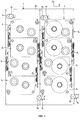
- FIG. 1 illustrates an embodiment of a creel 1 according to the invention, for example part of a machine placement of fiber, known per se, for example as described in the patent document WO2012 / 160270 .
- the creel 1 comprises a structure here formed of a vertical support wall 10, in one or more parts, mounted on a frame (not shown).
- the creel is provided here to receive eight fiber reels, in particular fiber reels provided with a protective film. Each fiber reel is obtained by a winding or slicing operation of regularly winding the spire fiber by turn and layer by layer over the entire length of a spool.
- the creel includes a set or module for each fiber reel.
- the modules bear the general reference 2, and are referenced individually from 2 1 to 2 8 on the figure 1 .
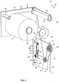
- each module 2 comprises a first mandrel 21 for receiving a fiber coil 9, a second mandrel 22 for rewinding the protective film, and a voltage control system 3.
- the voltage control system comprises a roller 31, said unwinding or deflagging, a so-called oscillating pulley 32 mounted at the end of an oscillating arm 33 and a return pulley 34.
- the first mandrel 21 extends perpendicular to the front face 10a of the support wall 10, and is connected to the end of the drive shaft of a motor 23 ( Fig. 4 ) for its rotational drive about its axis A1, arranged perpendicularly to the support wall 10.
- the mandrel is equipped with locking means, for example of the pneumatic type, for locking the coil in position on the mandrel.
- the motor is fixed on the rear face 10b of the support wall.
- Three orthogonal directions X, Y and Z are defined which will be used in the figures and in the description, Y being the direction of the axis A1, and X and Z being respectively the horizontal and vertical directions.
- the unwinding roll 31 of the voltage control system is shifted from the first mandrel 21 in the horizontal X direction.
- the unwinding roller is rotatably mounted about its axis A2 on the support wall, the axis A2 being parallel to the axis A1.
- the length of this unwinding roller corresponds substantially to the maximum length of coil that can be received by the first mandrel 21.
- the oscillating arm 33 is rotatably mounted by a first end about an axis A3, perpendicular to the axes A1 and A2, on a support plate 11 which is assembled on the support wall 10 and which extends perpendicularly from the front face 10a of the support wall in the Y direction.
- the axis A3 is shifted in the direction Z relative to the unwinding roller, and is disposed near the support wall.
- the oscillating arm extends perpendicularly to the support wall and carries at its second end the oscillating pulley 32 mounted to rotate about an axis A4 which is parallel to the axis A3.
- the pulley 34 is mounted on the support plate, rotatable about an axis A5 which is parallel to the axis A4.
- the return pulley is disposed between the unwinding roller 31 and the oscillating pulley 32.
- a jack 35 is pivotally mounted on the support plate by its cylinder body and the free end of its rod is assembled pivoting to the arm, the pivot axes of the cylinder being parallel to the axis A3.
- the cylinder is equipped with a position sensor 35a, for example magnetic type, to detect the position of the cylinder piston which is a function of the angular position of the arm.
- the sensor 35a is connected to a control unit of the fiber placement machine which, depending on the position signal of the jack, dynamically drives the motor to vary the rotational speed of the first mandrel.
- the oscillating arm is rotatable between a first stop 36 and a second stop 37.
- the fiber path is as follows: the fiber 91 unwound from the spool passes on the unwinding roller 31, on the oscillating pulley 32, then on the return pulley 34.
- the cylinder is a low friction type jack, known in itself, supplied with air under adjustable pressure, so as to be pre-loaded to ensure a return of the arm in abutment against the first stop 36 in the absence of tension in the fiber.
- the oscillating pulley 32 and the return pulley 34 are arranged in the same vertical plane which is substantially tangential to the cylindrical surface of the unwinding roll 31.
- the arm When the fiber is not unwound, the arm abuts against the first stop.
- a voltage is applied to the fiber, as illustrated by the arrow referenced T, for example when the fiber is draped by the fiber placement head, the arm pivots upwards in the case of the figure 4 , and the motor is controlled by the control unit to unwind the fiber coil according to the position of the cylinder detected by the position sensor.
- the tension of the fiber may vary, especially during acceleration or deceleration of the fiber.
- the arm pivots and the motor is dynamically controlled in speed according to the position of the jack. In operation, the motor is dynamically controlled so as to maintain the arm in a substantially horizontal position between the two stops, as shown in FIG. figure 4 .
- a second sensor 38 said overvoltage or safety, is provided to detect when the arm abuts against the second stop 37.
- the control unit stops the displacement of the placement head.
- the angular displacement of the oscillating arm between the two abutments 36, 37 is defined so as to obtain a linear displacement of the oscillating pulley in the Z direction of between 100 and 150 millimeters (mm), for example 125 mm.
- the distance between the unwinding roller 31 and the oscillating pulley 32 is defined to ensure efficient clearance of the fiber at an angle ⁇ without turning the fiber.
- the distance between the unwinding roller and the axis A3 of the oscillating arm is between 600 and 800 mm.
- the deflection pulley 34 is shifted in the Y direction beyond the oscillating pulley 32, to allow the clearance of the fiber at an angle ⁇ , without coming into contact with the return pulley.
- Each module 2 further comprises a sensor 39 for detecting the diameter of the coil which varies during draping.
- the sensor for example an ultrasonic sensor, is connected to the control unit which controls the motor 23 to define the speed of rotation of the coil according to its diameter.
- the second mandrel 22 is connected to the first mandrel 21 by a belt for its rotation drive to rewind the protective film as the course of the fiber.
- the connection between the two mandrels 21, 22 with the belt is performed by interposing a torque limiting system, known per se, to ensure the winding of the entire protective film regardless of the diameter of the fiber coil and the diameter of the protective film coil.
- the unwinding roller 31 is equipped with a longitudinal bar 40 defining a passage between said bar and the surface of the unwinding roller through which the fiber passes.
- the bar keeps the fiber on the roll and avoid a reversal of the latter.
- the bar is movable via actuating means (not shown) between a spaced position and a pinch position to pinch the fiber between the bar and the roller, and thus block it to perform butchering operations. .
- the fiber is blocked via the bar brought into the pinch position.
- the fiber is cut upstream of the bar and can then be spliced to the end of a fiber of a new fiber spool placed on the first mandrel.
- the creel comprises eight modules arranged in two columns of four superimposed modules. Each module is delimited by discontinuous lines on the figure 1 .
- the first column comprises a first module 2 1 which is oriented in the Z direction so that the oscillating pulley and the deflecting roller are arranged below the unwind roll, the fiber exiting the deflecting roller being oriented downwards.
- the second module 2 2 is oriented as the first module, and is disposed below the latter, with an offset in the X direction, for positioning on the left of the support plate of the first module carrying the oscillating pulley and the return pulley.
- the first mandrels of the first module and the second module are aligned vertically, as their second mandrels, the unwinding roller of the second module being in turn shifted horizontally to the left relative to that of the first module.
- the third module 23 is disposed below the second module and is oriented in the Z direction in the opposite direction with respect to the first and second modules, its oscillating pulley and its return pulley being disposed above its unwinding roller, the fiber coming out of its deflection pulley going up.
- first mandrel and second mandrel are positioned to the left of the support plates of the first and second modules, and its oscillating pulley and its return pulley are positioned to the left of the first and second mandrels of the first and second modules.
- the fourth module 24 is disposed under the third module and is oriented in the same direction as the latter.
- the second column comprises four nested modules like those of the first column, the two upper modules being oriented in the Z direction so that the fibers unrolled from these modules are recovered at the bottom of the creel, the two lower modules being oriented in the opposite direction in the direction Z, their fibers being recovered towards the top of the creel.
- the fibers emerging from the upper modules 2 1 , 2 2 , 2 5 , 2 6 of the two columns extend downwards and each pass on a lower return pulley 6 1 , 6 2 , 6 5 , 6 6 .
- the fibers emerging from the upper modules 2 3 , 2 4 , 2 7 , 2 8 of the two columns extend upwards and each pass on a lower return pulley 6 3 , 6 4 , 6 7 , 6 8 .
- These pulleys are mounted on horizontal bars fixed to the support wall. at the output of the lower and upper return pulleys, the fibers extend here to the right of the creel, they will then be grouped, for example at the top of the creel for their output creel and their routing to the fiber placement head.
- the elements of the modules can be mounted directly on the support wall. As illustrated in figure 1 the support wall is in two parts, the elements of the modules of the same column are mounted on the same part of the support wall.
- the creel is advantageously integrated in a cabinet which will preferably be regulated in hygrometry and temperature.
- the creel can be placed on the ground near the placement head, for example in the case of a poly-articulated robot fixed to the ground carrying the fiber placement head, or can be mounted on an element of the head displacement system, for example on one of the carriages of a Cartesian robot carrying the head, or a follower carriage sliding on the linear axis of a polyarticulated robot carrying the head.
- the motors of the first mandrels are controlled independently of each other by the control unit of the fiber placement machine.
- the creel can incorporate a tension limiter system, as described in the patent document EP 1 855 870 , especially when the fiber conveyance means are formed of flexible tubes.
- the creel with motorized chucks can be loaded with large spools of fibers, for example of the order of 15kg.
- the creel according to the invention can be used for storing and dispensing reels of fibers of different kinds.
- the fibers are carbon fibers, glass fibers, aramid fibers, polyethylene fibers, and / or fibers, for example natural fibers, such as, for example, flax fibers.
- the fibers may be fibers pre-impregnated with a thermoplastic or thermosetting resin, dry fibers, and / or dry fibers provided with a binder, to impart stickiness to the fibers during draping.
- the fibers have a width of 1/8, 1/4 or 1/2 inch.
- each first mandrel in the case of a fiber coil of smaller size, for example of the order of 3-4 kg, is rotatably mounted on the support wall and is for example equipped with an automatic braking system controlled according to the tension of the fiber.
- the braking system is controlled according to the position of the swingarm, the control being for example mechanical, pneumatic or electric.
- the signal from the position sensor fitted to the aforementioned ram is used to control the braking system.
Landscapes
- Engineering & Computer Science (AREA)
- Robotics (AREA)
- Chemical & Material Sciences (AREA)
- Composite Materials (AREA)
- Mechanical Engineering (AREA)
- Moulding By Coating Moulds (AREA)
Claims (12)
- Gatter für Faserspule, umfassend mindestens ein Modul (2) für eine Faserspule (9), wobei jedes Modul mindestens einen Dorn (21) zur Aufnahme einer Faserspule umfasst, der um eine erste Drehachse (A1) drehbar montiert ist, und ein System zur Spannkontrolle (3) der Faser, dadurch gekennzeichnet, dass das System zur Spannkontrolle für jedes Modul umfasst- eine Abwickelrolle (31), die um eine zweite Drehachse (A2), parallel zur ersten Achse (A1) drehbar montiert ist,- eine Schwinge (33), die um eine dritte Drehachse (A3) senkrecht zur ersten Achse und zur zweiten Achse, schwenkbar montiert ist, und an ihrem Ende eine Schwingscheibe (32) tragend, die um eine vierte Achse (A4) parallel zur dritten Achse, drehbar montiert ist, und- eine Umlenkscheibe (34), die um eine fünfte Drehachse (A5), parallel zur vierten Achse, drehbar montiert ist, die zwischen der Abwickelrolle (31) und der Schwingscheibe (32) angeordnet ist,
wobei die von der Spule abgewickelte Faser (91) über die Abwickelrolle (31), die Schwingscheibe (32) und dann die Umlenkscheibe (34) läuft, wobei die Drehung des ersten Dorns (21) in Abhängigkeit von der Position der Schwinge (33) kontrolliert wird. - Gatter nach Anspruch 1, dadurch gekennzeichnet, dass bei jedem Modul die erste Achse (A1) des ersten Dorns (31) und die zweite Achse (A2) der Abwickelrolle (31) parallel zu einer ersten Richtung (Y) sind,- die zweite Achse (A2) der Abwickelrolle von der ersten Achse (A1) des ersten Dorns in eine zweite Richtung (X), senkrecht zu der ersten Richtung, versetzt ist,- die vierte Achse (A4) der Schwingscheibe (32) und die fünfte Achse (A5) der Umlenkscheibe (34) im Verhältnis zur Abwickelrolle in eine dritte Richtung (Z) senkrecht zu der ersten und zweiten Richtung versetzt sind.
- Gatter nach Anspruch 1 oder 2, dadurch gekennzeichnet, dass die Schwingscheibe (32) und die Umlenkscheibe (34) in einer im Wesentlichen tangentialen Ebene zu der zylindrischen Oberfläche der Abwickelrolle (31) angeordnet sind.
- Gatter nach einem der Ansprüche 1 bis 3, dadurch gekennzeichnet, dass die dritte, vierte und fünfte Achse (A3, A4, A5) in der zweiten Richtung (X) angeordnet sind, die im Wesentlichen horizontal ist, wobei der Faserweg zwischen der Abwickelrolle (31), der Schwingscheibe (32) und der Umlenkscheine (34) in einer im Wesentlichen vertikalen Ebene durchgeführt wird.
- Gatter nach einem der Ansprüche 2 bis 4, dadurch gekennzeichnet, dass das Gatter mindestens zwei Module umfasst, die umgekehrt in der dritten Richtung (Z) angeordnet sind.
- Gatter nach einem der Ansprüche 1 bis 5, dadurch gekennzeichnet, dass jedes Modul (2) einen Motor (23) umfasst, der imstande ist, den ersten Dorn (21) in Drehung zu versetzen, wobei der Motor kontrolliert wird, um den ersten Dorn (21) in Abhängigkeit von der Position der Schwinge (33) in Drehung zu versetzen.
- Gatter nach einem der Ansprüche 1 bis 6, dadurch gekennzeichnet, dass jedes Modul (2) einen Zylinder (35) umfasst, der mit der Schwinge verbunden ist, wobei der Zylinder mit einem Positionssensor (35a) ausgerüstet ist, wobei die Drehung des ersten Dorns (21) in Abhängigkeit von der Position des von dem Positionssensor detektierten Zylinders kontrolliert wird.
- Gatter nach einem der Ansprüche 1 bis 7, dadurch gekennzeichnet, dass jedes Modul (2) weiter einen Durchmessersensor (39) umfasst, der imstande ist, den Durchmesser der Faserspule (9), die auf dem ersten Dorn (21) platziert ist, zu detektierten, wobei der Motor (31) kontrolliert ist, um den ersten Dorn (21) in Abhängigkeit von dem durch den Durchmessersensor (33) detektierten Durchmesser in Drehung zu versetzen.
- Gatter nach einem der Ansprüche 1 ä 8, dadurch gekennzeichnet, dass jedes Modul (2) weiter einen zweiten Dorn (22) zur Aufnahme einer Spule zum Rückspulen der Trennfolie einer Faserspule umfasst.
- Gatter nach einem der Ansprüche 1 ä 9, dadurch gekennzeichnet, dass die Abwickelrolle (31) mit einer Längsstange (40) ausgerüstet ist, um die Faser auf der Abwickelrolle zu führen, wobei die Stange zwischen einer abgespreizten Position und einer Klemmposition verschiebbar ist, um die Faser bei Anfügearbeiten zwischen der Stange und der Rolle zu klemmen.
- Maschine zum Anlegen von Fasern, dadurch gekennzeichnet, dass sie ein Gatter nach einem der Ansprüche 1 bis 10 umfasst.
- Verfahren zur Herstellung von Werkstücken aus Verbundmaterial, welches das Drapieren von Fasern auf einer Anlegeoberfläche umfasst, dadurch gekennzeichnet, dass das Drapieren anhand einer Maschine zum Anlegen von Fasern nach Anspruch 11 realisiert wird.
Applications Claiming Priority (2)
| Application Number | Priority Date | Filing Date | Title |
|---|---|---|---|
| FR1501197A FR3037330B1 (fr) | 2015-06-09 | 2015-06-09 | Cantre pour bobine de fibre |
| PCT/FR2016/000089 WO2016198755A1 (fr) | 2015-06-09 | 2016-05-25 | Cantre pour bobine de fibre |
Publications (2)
| Publication Number | Publication Date |
|---|---|
| EP3307662A1 EP3307662A1 (de) | 2018-04-18 |
| EP3307662B1 true EP3307662B1 (de) | 2019-07-03 |
Family
ID=53879539
Family Applications (1)
| Application Number | Title | Priority Date | Filing Date |
|---|---|---|---|
| EP16730440.1A Active EP3307662B1 (de) | 2015-06-09 | 2016-05-25 | Gatter für faserspule |
Country Status (3)
| Country | Link |
|---|---|
| EP (1) | EP3307662B1 (de) |
| FR (1) | FR3037330B1 (de) |
| WO (1) | WO2016198755A1 (de) |
Families Citing this family (9)
| Publication number | Priority date | Publication date | Assignee | Title |
|---|---|---|---|---|
| US9856106B1 (en) * | 2016-06-29 | 2018-01-02 | The Boeing Company | Dynamic feeding systems for knitting machines |
| CN108100640A (zh) * | 2018-01-04 | 2018-06-01 | 泰山玻璃纤维有限公司 | 基于视觉精确定位的短切纤维自动上纱系统 |
| CN108544769B (zh) * | 2018-04-23 | 2023-11-03 | 河北曜荣玻璃钢设备有限责任公司 | 玻璃钢管缠绕机及缠绕方法 |
| US11478997B2 (en) * | 2019-09-12 | 2022-10-25 | The Boeing Company | Automated fiber placement system and associated method |
| CN111693348A (zh) * | 2020-06-22 | 2020-09-22 | 重庆国际复合材料股份有限公司 | 一种玻璃纤维纱线制样系统及纱线制样方法 |
| US20220396040A1 (en) * | 2020-09-04 | 2022-12-15 | Fives Machining Systems, Inc. | Fiber placement machine with composite tape film removal |
| CN112141800A (zh) * | 2020-10-27 | 2020-12-29 | 湖南安圣电池有限公司 | 一种玻璃纤维丝放卷装置 |
| CN114228119B (zh) * | 2021-11-26 | 2022-07-08 | 合肥工业大学 | 一种悬臂丝嘴张力控制装置 |
| CN115056505B (zh) * | 2022-07-28 | 2023-09-05 | 西安英利科电气科技有限公司 | 球形核燃料外防护层的碳纤维球面缠绕设备及方法 |
Family Cites Families (8)
| Publication number | Priority date | Publication date | Assignee | Title |
|---|---|---|---|---|
| US3384322A (en) * | 1966-06-15 | 1968-05-21 | Irc Inc | Tensioner |
| US4623101A (en) * | 1984-07-25 | 1986-11-18 | Brunswick Corporation | Filament tensioner |
| US6491773B1 (en) * | 2000-01-24 | 2002-12-10 | Alliant Techsystems Inc. | Position-controlled tensioner system |
| EP1392587A4 (de) * | 2001-05-08 | 2009-03-18 | Magnatech International L P | Drahtablaufsystem und -verfahren mit elektronischer längensteuerung |
| FR2882681B1 (fr) | 2005-03-03 | 2009-11-20 | Coriolis Composites | Tete d'application de fibres et machine correspondante |
| FR2913365B1 (fr) | 2007-03-06 | 2013-07-26 | Coriolis Composites Attn Olivier Bouroullec | Tete d'application de fibres avec systemes de coupe de fibres particuliers |
| US8955787B2 (en) * | 2010-11-16 | 2015-02-17 | Murata Machinery, Ltd. | Filament winding apparatus |
| FR2975335B1 (fr) | 2011-05-20 | 2013-05-17 | Coriolis Composites Attn Olivier Bouroullec | Machine d'application de fibres avec tubes flexibles d'acheminement de fibres munis de lames flexibles |
-
2015
- 2015-06-09 FR FR1501197A patent/FR3037330B1/fr not_active Expired - Fee Related
-
2016
- 2016-05-25 EP EP16730440.1A patent/EP3307662B1/de active Active
- 2016-05-25 WO PCT/FR2016/000089 patent/WO2016198755A1/fr not_active Ceased
Non-Patent Citations (1)
| Title |
|---|
| None * |
Also Published As
| Publication number | Publication date |
|---|---|
| FR3037330B1 (fr) | 2017-06-16 |
| FR3037330A1 (fr) | 2016-12-16 |
| EP3307662A1 (de) | 2018-04-18 |
| WO2016198755A1 (fr) | 2016-12-15 |
Similar Documents
| Publication | Publication Date | Title |
|---|---|---|
| EP3307662B1 (de) | Gatter für faserspule | |
| EP2480400B1 (de) | Automatisierte drapiervorrichtung und drapierverfahren für verbundstoffe | |
| FR3006938A1 (fr) | Tete d application de fibres bi directionnelle a deux rouleaux | |
| FR2915925A1 (fr) | Machine d'application de fibres avec systeme de changement d'outils | |
| EP3426452A1 (de) | Verfahren zur herstellung von vorformlingen mit anwendung eines bindemittels auf trockener faser und entsprechende maschine | |
| EP2152500B1 (de) | Verbundauflagekopf mit ausziehbarer vorrichtung zur trennung eines prepregs von seinem trägerband | |
| EP0301989A1 (de) | Maschine zum Abwickeln von Bahnen mit Gestellen für Wickelrollen | |
| FR3033140A1 (fr) | Procede de depose d'une bande de matiere et dispositif pour sa mise en oeuvre | |
| EP4100240A1 (de) | Faserapplikationskopf mit eingebauten rollen | |
| EP0795504B1 (de) | Maschine zum kontinuierlichen Abwickeln von Rollen mit zumindest einer Einrichtung zum gleichzeitigen Abwickeln von zwei paarweise oder koaxial angeordneten Rollen | |
| EP1036026B1 (de) | Wickelmaschine für bahnen, zum wickeln von rollen | |
| FR2670130A1 (fr) | Procede et dispositif de fabrication de faisceaux de fibres creuses semi-permeables pour appareil a membrane. | |
| WO2024105310A1 (fr) | Machine et procédé de placement de fibres | |
| FR2888156A1 (fr) | Guide mobile pour tete de drapage | |
| EP4267500B1 (de) | Vorrichtung zum abwickeln eines fadens von einer spule | |
| FR2867453A1 (fr) | Dispositif de pose sur un fardeau d'une poignee preparee | |
| EP4519070B1 (de) | Faserapplikationsmaschine mit applikationskopf mit einem spannungsbegrenzungssystem | |
| EP4452608B1 (de) | Faserapplikationsmaschine mit einem spannungsbegrenzungssystem | |
| EP3423262B1 (de) | Faserapplikationsmaschine mit bandförderer und verfahren zur herstellung von teilen unter verwendung solch einer maschine | |
| FR2880329A1 (fr) | Procede et dispositif de raccordement de deux gaines tubulaires aplaties dans une machine de pose de manchons sur des objets en defilement | |
| EP0619255A2 (de) | Vorrichtung zum Schneiden und Befestigen des Bahnanfanges einer neuen Rolle auf einem Wickelkern einer Wickelmaschine | |
| BE904294A (fr) | Machine pour debiter un ruban de matiere en sections et pour enrouler ces dernieres. |
Legal Events
| Date | Code | Title | Description |
|---|---|---|---|
| STAA | Information on the status of an ep patent application or granted ep patent |
Free format text: STATUS: THE INTERNATIONAL PUBLICATION HAS BEEN MADE |
|
| PUAI | Public reference made under article 153(3) epc to a published international application that has entered the european phase |
Free format text: ORIGINAL CODE: 0009012 |
|
| STAA | Information on the status of an ep patent application or granted ep patent |
Free format text: STATUS: REQUEST FOR EXAMINATION WAS MADE |
|
| 17P | Request for examination filed |
Effective date: 20171129 |
|
| AK | Designated contracting states |
Kind code of ref document: A1 Designated state(s): AL AT BE BG CH CY CZ DE DK EE ES FI FR GB GR HR HU IE IS IT LI LT LU LV MC MK MT NL NO PL PT RO RS SE SI SK SM TR |
|
| AX | Request for extension of the european patent |
Extension state: BA ME |
|
| RAP1 | Party data changed (applicant data changed or rights of an application transferred) |
Owner name: CORIOLIS GROUP |
|
| DAV | Request for validation of the european patent (deleted) | ||
| DAX | Request for extension of the european patent (deleted) | ||
| GRAP | Despatch of communication of intention to grant a patent |
Free format text: ORIGINAL CODE: EPIDOSNIGR1 |
|
| STAA | Information on the status of an ep patent application or granted ep patent |
Free format text: STATUS: GRANT OF PATENT IS INTENDED |
|
| INTG | Intention to grant announced |
Effective date: 20190118 |
|
| GRAS | Grant fee paid |
Free format text: ORIGINAL CODE: EPIDOSNIGR3 |
|
| GRAA | (expected) grant |
Free format text: ORIGINAL CODE: 0009210 |
|
| STAA | Information on the status of an ep patent application or granted ep patent |
Free format text: STATUS: THE PATENT HAS BEEN GRANTED |
|
| AK | Designated contracting states |
Kind code of ref document: B1 Designated state(s): AL AT BE BG CH CY CZ DE DK EE ES FI FR GB GR HR HU IE IS IT LI LT LU LV MC MK MT NL NO PL PT RO RS SE SI SK SM TR |
|
| REG | Reference to a national code |
Ref country code: GB Ref legal event code: FG4D Free format text: NOT ENGLISH |
|
| REG | Reference to a national code |
Ref country code: CH Ref legal event code: EP Ref country code: AT Ref legal event code: REF Ref document number: 1150747 Country of ref document: AT Kind code of ref document: T Effective date: 20190715 |
|
| REG | Reference to a national code |
Ref country code: DE Ref legal event code: R096 Ref document number: 602016016355 Country of ref document: DE |
|
| REG | Reference to a national code |
Ref country code: IE Ref legal event code: FG4D Free format text: LANGUAGE OF EP DOCUMENT: FRENCH |
|
| REG | Reference to a national code |
Ref country code: NL Ref legal event code: MP Effective date: 20190703 |
|
| REG | Reference to a national code |
Ref country code: LT Ref legal event code: MG4D |
|
| REG | Reference to a national code |
Ref country code: AT Ref legal event code: MK05 Ref document number: 1150747 Country of ref document: AT Kind code of ref document: T Effective date: 20190703 |
|
| PG25 | Lapsed in a contracting state [announced via postgrant information from national office to epo] |
Ref country code: PT Free format text: LAPSE BECAUSE OF FAILURE TO SUBMIT A TRANSLATION OF THE DESCRIPTION OR TO PAY THE FEE WITHIN THE PRESCRIBED TIME-LIMIT Effective date: 20191104 Ref country code: HR Free format text: LAPSE BECAUSE OF FAILURE TO SUBMIT A TRANSLATION OF THE DESCRIPTION OR TO PAY THE FEE WITHIN THE PRESCRIBED TIME-LIMIT Effective date: 20190703 Ref country code: LT Free format text: LAPSE BECAUSE OF FAILURE TO SUBMIT A TRANSLATION OF THE DESCRIPTION OR TO PAY THE FEE WITHIN THE PRESCRIBED TIME-LIMIT Effective date: 20190703 Ref country code: AT Free format text: LAPSE BECAUSE OF FAILURE TO SUBMIT A TRANSLATION OF THE DESCRIPTION OR TO PAY THE FEE WITHIN THE PRESCRIBED TIME-LIMIT Effective date: 20190703 Ref country code: NO Free format text: LAPSE BECAUSE OF FAILURE TO SUBMIT A TRANSLATION OF THE DESCRIPTION OR TO PAY THE FEE WITHIN THE PRESCRIBED TIME-LIMIT Effective date: 20191003 Ref country code: FI Free format text: LAPSE BECAUSE OF FAILURE TO SUBMIT A TRANSLATION OF THE DESCRIPTION OR TO PAY THE FEE WITHIN THE PRESCRIBED TIME-LIMIT Effective date: 20190703 Ref country code: SE Free format text: LAPSE BECAUSE OF FAILURE TO SUBMIT A TRANSLATION OF THE DESCRIPTION OR TO PAY THE FEE WITHIN THE PRESCRIBED TIME-LIMIT Effective date: 20190703 Ref country code: CZ Free format text: LAPSE BECAUSE OF FAILURE TO SUBMIT A TRANSLATION OF THE DESCRIPTION OR TO PAY THE FEE WITHIN THE PRESCRIBED TIME-LIMIT Effective date: 20190703 Ref country code: BG Free format text: LAPSE BECAUSE OF FAILURE TO SUBMIT A TRANSLATION OF THE DESCRIPTION OR TO PAY THE FEE WITHIN THE PRESCRIBED TIME-LIMIT Effective date: 20191003 Ref country code: NL Free format text: LAPSE BECAUSE OF FAILURE TO SUBMIT A TRANSLATION OF THE DESCRIPTION OR TO PAY THE FEE WITHIN THE PRESCRIBED TIME-LIMIT Effective date: 20190703 |
|
| PG25 | Lapsed in a contracting state [announced via postgrant information from national office to epo] |
Ref country code: RS Free format text: LAPSE BECAUSE OF FAILURE TO SUBMIT A TRANSLATION OF THE DESCRIPTION OR TO PAY THE FEE WITHIN THE PRESCRIBED TIME-LIMIT Effective date: 20190703 Ref country code: IS Free format text: LAPSE BECAUSE OF FAILURE TO SUBMIT A TRANSLATION OF THE DESCRIPTION OR TO PAY THE FEE WITHIN THE PRESCRIBED TIME-LIMIT Effective date: 20191103 Ref country code: LV Free format text: LAPSE BECAUSE OF FAILURE TO SUBMIT A TRANSLATION OF THE DESCRIPTION OR TO PAY THE FEE WITHIN THE PRESCRIBED TIME-LIMIT Effective date: 20190703 Ref country code: GR Free format text: LAPSE BECAUSE OF FAILURE TO SUBMIT A TRANSLATION OF THE DESCRIPTION OR TO PAY THE FEE WITHIN THE PRESCRIBED TIME-LIMIT Effective date: 20191004 Ref country code: AL Free format text: LAPSE BECAUSE OF FAILURE TO SUBMIT A TRANSLATION OF THE DESCRIPTION OR TO PAY THE FEE WITHIN THE PRESCRIBED TIME-LIMIT Effective date: 20190703 Ref country code: ES Free format text: LAPSE BECAUSE OF FAILURE TO SUBMIT A TRANSLATION OF THE DESCRIPTION OR TO PAY THE FEE WITHIN THE PRESCRIBED TIME-LIMIT Effective date: 20190703 |
|
| PG25 | Lapsed in a contracting state [announced via postgrant information from national office to epo] |
Ref country code: TR Free format text: LAPSE BECAUSE OF FAILURE TO SUBMIT A TRANSLATION OF THE DESCRIPTION OR TO PAY THE FEE WITHIN THE PRESCRIBED TIME-LIMIT Effective date: 20190703 |
|
| PG25 | Lapsed in a contracting state [announced via postgrant information from national office to epo] |
Ref country code: PL Free format text: LAPSE BECAUSE OF FAILURE TO SUBMIT A TRANSLATION OF THE DESCRIPTION OR TO PAY THE FEE WITHIN THE PRESCRIBED TIME-LIMIT Effective date: 20190703 Ref country code: RO Free format text: LAPSE BECAUSE OF FAILURE TO SUBMIT A TRANSLATION OF THE DESCRIPTION OR TO PAY THE FEE WITHIN THE PRESCRIBED TIME-LIMIT Effective date: 20190703 Ref country code: IT Free format text: LAPSE BECAUSE OF FAILURE TO SUBMIT A TRANSLATION OF THE DESCRIPTION OR TO PAY THE FEE WITHIN THE PRESCRIBED TIME-LIMIT Effective date: 20190703 Ref country code: EE Free format text: LAPSE BECAUSE OF FAILURE TO SUBMIT A TRANSLATION OF THE DESCRIPTION OR TO PAY THE FEE WITHIN THE PRESCRIBED TIME-LIMIT Effective date: 20190703 Ref country code: DK Free format text: LAPSE BECAUSE OF FAILURE TO SUBMIT A TRANSLATION OF THE DESCRIPTION OR TO PAY THE FEE WITHIN THE PRESCRIBED TIME-LIMIT Effective date: 20190703 |
|
| PG25 | Lapsed in a contracting state [announced via postgrant information from national office to epo] |
Ref country code: IS Free format text: LAPSE BECAUSE OF FAILURE TO SUBMIT A TRANSLATION OF THE DESCRIPTION OR TO PAY THE FEE WITHIN THE PRESCRIBED TIME-LIMIT Effective date: 20200224 Ref country code: SM Free format text: LAPSE BECAUSE OF FAILURE TO SUBMIT A TRANSLATION OF THE DESCRIPTION OR TO PAY THE FEE WITHIN THE PRESCRIBED TIME-LIMIT Effective date: 20190703 Ref country code: SK Free format text: LAPSE BECAUSE OF FAILURE TO SUBMIT A TRANSLATION OF THE DESCRIPTION OR TO PAY THE FEE WITHIN THE PRESCRIBED TIME-LIMIT Effective date: 20190703 |
|
| REG | Reference to a national code |
Ref country code: DE Ref legal event code: R097 Ref document number: 602016016355 Country of ref document: DE |
|
| PLBE | No opposition filed within time limit |
Free format text: ORIGINAL CODE: 0009261 |
|
| STAA | Information on the status of an ep patent application or granted ep patent |
Free format text: STATUS: NO OPPOSITION FILED WITHIN TIME LIMIT |
|
| PG2D | Information on lapse in contracting state deleted |
Ref country code: IS |
|
| 26N | No opposition filed |
Effective date: 20200603 |
|
| PG25 | Lapsed in a contracting state [announced via postgrant information from national office to epo] |
Ref country code: SI Free format text: LAPSE BECAUSE OF FAILURE TO SUBMIT A TRANSLATION OF THE DESCRIPTION OR TO PAY THE FEE WITHIN THE PRESCRIBED TIME-LIMIT Effective date: 20190703 |
|
| PG25 | Lapsed in a contracting state [announced via postgrant information from national office to epo] |
Ref country code: LI Free format text: LAPSE BECAUSE OF NON-PAYMENT OF DUE FEES Effective date: 20200531 Ref country code: CH Free format text: LAPSE BECAUSE OF NON-PAYMENT OF DUE FEES Effective date: 20200531 Ref country code: MC Free format text: LAPSE BECAUSE OF FAILURE TO SUBMIT A TRANSLATION OF THE DESCRIPTION OR TO PAY THE FEE WITHIN THE PRESCRIBED TIME-LIMIT Effective date: 20190703 |
|
| REG | Reference to a national code |
Ref country code: BE Ref legal event code: MM Effective date: 20200531 |
|
| PG25 | Lapsed in a contracting state [announced via postgrant information from national office to epo] |
Ref country code: LU Free format text: LAPSE BECAUSE OF NON-PAYMENT OF DUE FEES Effective date: 20200525 |
|
| PG25 | Lapsed in a contracting state [announced via postgrant information from national office to epo] |
Ref country code: IE Free format text: LAPSE BECAUSE OF NON-PAYMENT OF DUE FEES Effective date: 20200525 |
|
| PG25 | Lapsed in a contracting state [announced via postgrant information from national office to epo] |
Ref country code: BE Free format text: LAPSE BECAUSE OF NON-PAYMENT OF DUE FEES Effective date: 20200531 |
|
| PG25 | Lapsed in a contracting state [announced via postgrant information from national office to epo] |
Ref country code: MT Free format text: LAPSE BECAUSE OF FAILURE TO SUBMIT A TRANSLATION OF THE DESCRIPTION OR TO PAY THE FEE WITHIN THE PRESCRIBED TIME-LIMIT Effective date: 20190703 Ref country code: CY Free format text: LAPSE BECAUSE OF FAILURE TO SUBMIT A TRANSLATION OF THE DESCRIPTION OR TO PAY THE FEE WITHIN THE PRESCRIBED TIME-LIMIT Effective date: 20190703 |
|
| PG25 | Lapsed in a contracting state [announced via postgrant information from national office to epo] |
Ref country code: MK Free format text: LAPSE BECAUSE OF FAILURE TO SUBMIT A TRANSLATION OF THE DESCRIPTION OR TO PAY THE FEE WITHIN THE PRESCRIBED TIME-LIMIT Effective date: 20190703 |
|
| PGFP | Annual fee paid to national office [announced via postgrant information from national office to epo] |
Ref country code: GB Payment date: 20220426 Year of fee payment: 7 |
|
| PGFP | Annual fee paid to national office [announced via postgrant information from national office to epo] |
Ref country code: DE Payment date: 20230419 Year of fee payment: 8 |
|
| GBPC | Gb: european patent ceased through non-payment of renewal fee |
Effective date: 20230525 |
|
| PG25 | Lapsed in a contracting state [announced via postgrant information from national office to epo] |
Ref country code: GB Free format text: LAPSE BECAUSE OF NON-PAYMENT OF DUE FEES Effective date: 20230525 |
|
| REG | Reference to a national code |
Ref country code: DE Ref legal event code: R119 Ref document number: 602016016355 Country of ref document: DE |
|
| PG25 | Lapsed in a contracting state [announced via postgrant information from national office to epo] |
Ref country code: DE Free format text: LAPSE BECAUSE OF NON-PAYMENT OF DUE FEES Effective date: 20241203 |
|
| PGFP | Annual fee paid to national office [announced via postgrant information from national office to epo] |
Ref country code: FR Payment date: 20250424 Year of fee payment: 10 |