EP0361777A2 - Lubrication of printed circuit card contact tabs - Google Patents
Lubrication of printed circuit card contact tabs Download PDFInfo
- Publication number
- EP0361777A2 EP0361777A2 EP89309577A EP89309577A EP0361777A2 EP 0361777 A2 EP0361777 A2 EP 0361777A2 EP 89309577 A EP89309577 A EP 89309577A EP 89309577 A EP89309577 A EP 89309577A EP 0361777 A2 EP0361777 A2 EP 0361777A2
- Authority
- EP
- European Patent Office
- Prior art keywords
- lubricant
- applicator
- conveying
- rollers
- printed circuit
- Prior art date
- Legal status (The legal status is an assumption and is not a legal conclusion. Google has not performed a legal analysis and makes no representation as to the accuracy of the status listed.)
- Withdrawn
Links
Images


Classifications
-
- H—ELECTRICITY
- H05—ELECTRIC TECHNIQUES NOT OTHERWISE PROVIDED FOR
- H05K—PRINTED CIRCUITS; CASINGS OR CONSTRUCTIONAL DETAILS OF ELECTRIC APPARATUS; MANUFACTURE OF ASSEMBLAGES OF ELECTRICAL COMPONENTS
- H05K3/00—Apparatus or processes for manufacturing printed circuits
- H05K3/0091—Apparatus for coating printed circuits using liquid non-metallic coating compositions
-
- B—PERFORMING OPERATIONS; TRANSPORTING
- B05—SPRAYING OR ATOMISING IN GENERAL; APPLYING FLUENT MATERIALS TO SURFACES, IN GENERAL
- B05C—APPARATUS FOR APPLYING FLUENT MATERIALS TO SURFACES, IN GENERAL
- B05C1/00—Apparatus in which liquid or other fluent material is applied to the surface of the work by contact with a member carrying the liquid or other fluent material, e.g. a porous member loaded with a liquid to be applied as a coating
- B05C1/04—Apparatus in which liquid or other fluent material is applied to the surface of the work by contact with a member carrying the liquid or other fluent material, e.g. a porous member loaded with a liquid to be applied as a coating for applying liquid or other fluent material to work of indefinite length
- B05C1/08—Apparatus in which liquid or other fluent material is applied to the surface of the work by contact with a member carrying the liquid or other fluent material, e.g. a porous member loaded with a liquid to be applied as a coating for applying liquid or other fluent material to work of indefinite length using a roller or other rotating member which contacts the work along a generating line
-
- H—ELECTRICITY
- H05—ELECTRIC TECHNIQUES NOT OTHERWISE PROVIDED FOR
- H05K—PRINTED CIRCUITS; CASINGS OR CONSTRUCTIONAL DETAILS OF ELECTRIC APPARATUS; MANUFACTURE OF ASSEMBLAGES OF ELECTRICAL COMPONENTS
- H05K1/00—Printed circuits
- H05K1/02—Details
- H05K1/11—Printed elements for providing electric connections to or between printed circuits
- H05K1/117—Pads along the edge of rigid circuit boards, e.g. for pluggable connectors
-
- H—ELECTRICITY
- H05—ELECTRIC TECHNIQUES NOT OTHERWISE PROVIDED FOR
- H05K—PRINTED CIRCUITS; CASINGS OR CONSTRUCTIONAL DETAILS OF ELECTRIC APPARATUS; MANUFACTURE OF ASSEMBLAGES OF ELECTRICAL COMPONENTS
- H05K2203/00—Indexing scheme relating to apparatus or processes for manufacturing printed circuits covered by H05K3/00
- H05K2203/01—Tools for processing; Objects used during processing
- H05K2203/0104—Tools for processing; Objects used during processing for patterning or coating
- H05K2203/0143—Using a roller; Specific shape thereof; Providing locally adhesive portions thereon
-
- H—ELECTRICITY
- H05—ELECTRIC TECHNIQUES NOT OTHERWISE PROVIDED FOR
- H05K—PRINTED CIRCUITS; CASINGS OR CONSTRUCTIONAL DETAILS OF ELECTRIC APPARATUS; MANUFACTURE OF ASSEMBLAGES OF ELECTRICAL COMPONENTS
- H05K2203/00—Indexing scheme relating to apparatus or processes for manufacturing printed circuits covered by H05K3/00
- H05K2203/12—Using specific substances
- H05K2203/127—Lubricants, e.g. during drilling of holes
-
- H—ELECTRICITY
- H05—ELECTRIC TECHNIQUES NOT OTHERWISE PROVIDED FOR
- H05K—PRINTED CIRCUITS; CASINGS OR CONSTRUCTIONAL DETAILS OF ELECTRIC APPARATUS; MANUFACTURE OF ASSEMBLAGES OF ELECTRICAL COMPONENTS
- H05K2203/00—Indexing scheme relating to apparatus or processes for manufacturing printed circuits covered by H05K3/00
- H05K2203/15—Position of the PCB during processing
- H05K2203/1509—Horizontally held PCB
-
- H—ELECTRICITY
- H05—ELECTRIC TECHNIQUES NOT OTHERWISE PROVIDED FOR
- H05K—PRINTED CIRCUITS; CASINGS OR CONSTRUCTIONAL DETAILS OF ELECTRIC APPARATUS; MANUFACTURE OF ASSEMBLAGES OF ELECTRICAL COMPONENTS
- H05K2203/00—Indexing scheme relating to apparatus or processes for manufacturing printed circuits covered by H05K3/00
- H05K2203/15—Position of the PCB during processing
- H05K2203/1572—Processing both sides of a PCB by the same process; Providing a similar arrangement of components on both sides; Making interlayer connections from two sides
Definitions
- the present invention relates to lubricating electrical contact tabs located along the edges of printed circuit cards. More specifically it relates to automatically and reliably applying uniform amounts of liquid lubricant to electrical contact tabs.
- a lubricant can have beneficial electrical as well as mechanical effects.
- a lubricant when applied to separable contacts as a thin film reduces friction and wear during sliding action of contacting surfaces. Wear reduction is particularly important where thin precious metal plating is used over base metal.
- a method for use in a manufacturing process for applying a thin, uniform layer of lubricant on gold contact tabs is desirable.
- Conventional methods include felt tips with lubricant, cotton swabs with lubricant, and wiping on lubricant with a lint free cloth.
- the main drawback of these methods is that the amount of lubricant on contact tabs is not consistent due to the manual nature of the methods.
- the lubrication process In an automated production environment, it is desirable for the lubrication process to perform several functions including supplying a continuous lubricant film in controlled amounts while moving a card past the supply point at a controllable speed, while accommodating card thickness variations.
- the present invention seeks to provide apparatus and a method for applying uniform amounts of liquid lubricant in a reliable, consistently repeatable manner to electrical contacts located along an edge of printed circuit cards conveyed at a uniform rate of speed past a lubricant applying station.
- the invention provides apparatus for applying uniform amounts of liquid lubricant to electrical contact tabs located along an edge of a printed circuit card, comprising first free rolling lubricant applicator means; lubricant supplying means, including at least one wicking member for supplying lubricant to said applicator means and conveying means for conveying a printed circuit card along a linear path at a predetermined, constant rate of speed in wiping contact past said lubricant applicator means.
- the invention provides a method of applying uniform amounts of liquid lubricant to planar electrical contacts located along an edge of a printed circuit board comprising providing a first station having a lintless applicator with a continuous supply of lubricant; and conveying said circuit board at a predetermined constant rate in a linear path past said applicator in wiping contact therewith.
- Rollers are provided for conveying the cards. Rollers may be mounted on an adjustable block so that spacing between rollers can be varied to accommodate different card thicknesses. A rail may be used to guide a card through the rollers and provide a reference for control of oil film thickness with respect to tab edge.
- Lubricant flow adjustment may be made at the lubricant reservoir and is affected by factors such as card speed and geometrical attributes of gold tabs. Desired flow rate may be determined by lubing a run ahead sample so as to obtain a uniform oil film on tabs without oil globs or oil starvation. Card speed may be adjusted.
- Lubricant applicator drive rollers should be cleaned periodically with a lint free cloth. When not in use, precautions should be taken to avoid dust accumulations on the lubricant application rollers.
- Fig. 1 is a schematic illustration of apparatus embodying the present invention.
- the lubricating apparatus is attached to mounting plate 1.
- Printed circuit card 2 has a variety of components inserted or mounted thereon. These components are not shown as they are not part of the present invention. Circuitry not shown on the card 2 terminates in edge contact tabs 4, which are typically plated with gold. It is these electrical contact tabs 4 which are shown along one side of card 2; they may also be provided along the other linear edge, and on one or both linear edges on the opposite planar side as well.
- Lubricant is desirably provided on edge tabs 4 as one of the final steps after the component assembly in the manufacture of the printed circuit card.
- a lubricant is preferably chosen to have characteristics which will enable it to last the useful life of the card.
- lubricant from source 10 is supplied through appropriate piping 12 to a lubrication station indicated generally at 14. Lubricant is applied to edge contact tabs 4 as they pass in wiping contact with lubricant applicator rollers 16. Rollers 16 are free rolling and mounted on studs 17 in plate 1. It has been found that two rollers 16 usually provide better coverage than a single roller.
- applicator station 14 The structure of applicator station 14 will be discussed in greater detail in connection with Fig. 4.
- Means are provided for conveying card 2 at a uniform rate of speed past lubrication station 14 in the direction of arrow 18.
- Motor 30 is provided for driving entry roller pair 32, 32′ and exit roller pair 36, 36′.
- Rollers 32, 32′, 36 and 36′ convey card 2, the edge of which to be lubricated is aligned by means of guide rail 38.
- FIG. 1 a rear view of the apparatus of Fig. 1 with mounting plate 1 removed for clarity.
- Motor 30 drives shafts 46 and 48 via belt 40.
- Shaft 46 drives rollers 32 and 32′.
- Shaft 48 drives rollers 36 and 36′ in the direction as shown in Fig. 1. It is extremely important that rollers 32, 32′, 36 and 36′ be driven in synchronism so that they rotate at the same constant rate.
- One motor with appropriate motion transmission mechanism may be used. Those having skill in the art will understand this is not a necessary limitation and that other motive means may be used.
- Shaft 46 terminates in worm screw 50 adjacent worm wheel 52 which is drivingly attached to feed roller 32 via shaft 54.
- worm wheel 56 driven by worm screw 50, drives shaft 58 fixedly attached to feed roller 32′.
- Shaft 48 terminates in worm screw 60 which drives worm wheels 62 and 66.
- Worm wheel 62 drives exit roller 36 via shaft 64.
- exit roller 36′ is driven by worm wheel 66 via shaft 68.
- rollers 32 and 32′, 36 and 36′ may be adjustable along their respective shafts 54, 58, 64 and 68, so that depending on the layout of components on a given card, a linear path parallel to the contact edge of a card 2 is described. In any case, rollers 32 and 36 should contact the surface of card 2 and define a linear path so as not to interfere with or damage components on card 2.
- Fig. 3A is a schematic cross-section of any of the drive or exit rollers 32, 32′, 36, 36′.
- Each roller has a cylindrical portion 80 and a frusto conical portion 82 such that the roller taken as a whole is frusto conical in shape.
- the angle 84 of the cone is preferably in the range of 5-10 degrees.
- Fig. 3B shows the deformation of roller portions 80 and 82 as the roller rotates. Thus, the deformation of the portion 82 is toward rail 38 of Fig. 1.
- the phenomenon of conical rollers having both an edge aligning and forward driving face components is well known.
- exit rollers 36 and 36′ provide the advantage of smearing oil applied at lubricating station 14.
- the combined results of the free rotation of lubrication applicator rollers 16 and exit rollers 36 and 36′ is to assure the smooth distribution of the lubricant and eliminate any spotty oil deposits.
- Rollers 32, 32′, 36 and 36′ which comprise the entry and exit roller pairs are spaced apart from each other a distance somewhat less than the thickness of the card edge to be lubricated. It has been found that the distance between upper rollers, 32 and 35, and their lower cooperating rollers, 32′ and 36′ should be 0.025 to 0.051cm (0.010 ⁇ to 0.020 ⁇ ) less than the thickness t of the card 2 having its edge tabs 4 lubricated (Fig.1).
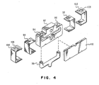
- FIG. 4 is an exploded view of a lubricating station 14.
- a generally Y shaped felt wick 90 is inserted into block 92 so that the upright ends of felt wick 90 protrude somewhat through holes 94 and 96 in block 92.
- Two lintless fiber pads 98 are provided and held in place with clips 102 and 104. Holes 106 and 108 in clips 102 and 104 allow oil filtered through pads 98 to be presented to rollers 16 (Fig. 1)
- Cover plate 110 completes the subassembly.
- Not shown in Fig. 4 but shown in Fig. 5 is the place at which piping 12 enters lubricating station 14 for continuously supplying oil from source to wick 90.
- the ends of wick 90 protrude somewhat through the holes 106 and 108 provided in metal spring clips 102 and 104 respectively.
- Pads 98 prevent transfer of fibres from wick 90 to rollers 16.
- Fig. 5 is a schematic diagram showing only those parts of the apparatus relating to oil supply.
- lubricant from source 10 which may be any suitable commercially available regulated gravity feed device, is provided to applicator rollers 16 from wicking member 90 to which lubricant is directly supplied.
- wicking member 90 In abutting relationship to both wicking member 90 and applicator roller 16, are lintless, fibrous pads 98 (Fig.4). With each rotation of rollers 16, their surface contacts pads 98.
- the two lubricating stations 14 shown in Figs. 1, 2, 4, and 5 are constructed exactly alike. If edge connector tabs on parallel sides on the same planar surface of a circuit board 2 are to be lubricated, a mirror image of the apparatus shown and described in connection with Figs. 1, 2 and 5 is provided.
- wick 90 is 0.6cm (quarter inch) diameter felt.
- Felt wicking of this type is commercially available and manufactured for oil lubricating systems that deliver lubricants from a reservoir to a bearing surface. Gravity feed oil reservoirs are also commercially available and therefore not shown in detail.
- rail 38 has been illustrated for guiding card 2 through the apparatus, other guide means are possible.
- rollers may be provided in mounting plate 1 at spaced intervals with the surface of the plate 1 adjacent card 2 having an indentation against which the card edge may be aligned, in the same manner as rail 38.
- Fig. 6 is illustrative of one embodiment of the present invention in which rollers 16 are formed preferably of treated rubber having a roughened surface.
- Helical grooves 122 generally perpendicular to stud 17 (Fig. 1) are provided to improve retention of lubricant oil on the roller surface. It has been found that grooves having a depth of about 0.075cm (0.030 inch) at 3 threads per cm (8 threads per inch (TP1)) provide good results.
- TP1 threads per inch
- Fig. 7 shows another suitable lubricating roller 16 with a lintless material 130 on its surface.
- lintless material 130 is cotton and has a thickness of 0.025 to 0.076cm (.010 - .030 inch).
- a suitable lubricant for use with this material is Stauffer Electronic Lubricant CL-920. Other materials may be used as appropriate to the characteristics of the lubricant to be applied.
- the apparatus shown in Fig. 1 may be embodied as a last step in a single side printed circuit manufacture facility or as a separate process at another site.
- cards requiring edge connector lubrication are conveyed under the influence of drive rollers 32 and 32′ and exit rollers 36 and 36′, so as to lubricate edge connector tabs 4 through wiping contact with applicator rollers 16.
- Roller pairs 32-32′, 36-36′ are positioned such that the distance between them is somewhat less in thickness than that of a printed circuit card 2 to be driven by the roller pairs. A difference of about 0.025 to 0.051cm (0.010 - 0.020 in.) is preferred.
Landscapes
- Engineering & Computer Science (AREA)
- Manufacturing & Machinery (AREA)
- Microelectronics & Electronic Packaging (AREA)
- Coating Apparatus (AREA)
- Manufacturing Of Electrical Connectors (AREA)
Abstract
Uniform amounts of liquid lubricant are applied to planar electrical contact tabs (4) located along an edge of a printed circuit board by conveying the circuit board (by rollers 32, 32′, 36, 26′) at a constant rate past a lintless lubricant applicator roller (16) which receives a continuous supply of lubricant via a wicking member (90)
Description
- The present invention relates to lubricating electrical contact tabs located along the edges of printed circuit cards. More specifically it relates to automatically and reliably applying uniform amounts of liquid lubricant to electrical contact tabs.
- In the computer industry, there is frequently a need to replace printed circuit cards during the life of a machine. Galling and brittle fracture of noble plating material occurs when contact force per unit area exceeds the strength of the substrate metal. Failure of a connector through increased resistance can be caused by excessive wear resulting from friction of mating parts and may also cause interference with operation of the connector. Excessive wear is detrimental from an electrical as well as a mechanical view point.
- It is known that a lubricant can have beneficial electrical as well as mechanical effects. A lubricant when applied to separable contacts as a thin film reduces friction and wear during sliding action of contacting surfaces. Wear reduction is particularly important where thin precious metal plating is used over base metal.
- A method for use in a manufacturing process for applying a thin, uniform layer of lubricant on gold contact tabs is desirable. Conventional methods include felt tips with lubricant, cotton swabs with lubricant, and wiping on lubricant with a lint free cloth. The main drawback of these methods is that the amount of lubricant on contact tabs is not consistent due to the manual nature of the methods.
- Therefore, it is desirable to ensure that card contact edges are lubricated at the time of manufacture with a sufficient amount of lubricant to enable specified insertions and retractions of such cards during their useful life. In some instances this lifetime may be expected to last for up to five years and include as many as 25 insertions/retractions. It has been found that liquid lubricants are most effective for providing lifetime lubrication at the time the cards are manufactured. However, the problem of ensuring uniform application of lubricant has not been solved with total success; and in fact it is often a manual step - with its inherent deficiencies in repeatability and reliability.
- Other methods of lubricating printed circuitry have included applying a layer of spray wax and using rollers such as taught in US-A- 4,159,222. US-A-4,268,568 describes electrical contacts on printed circuit boards, which contacts incorporate a fluorocarbon polymer film as a lubricant. US-A-4,529,531 and US-A-4,530,772 disclose electric contact lubricants and methods of using them. In each case the method comprises adding the disclosed lubricant to the contacts.
- In an automated production environment, it is desirable for the lubrication process to perform several functions including supplying a continuous lubricant film in controlled amounts while moving a card past the supply point at a controllable speed, while accommodating card thickness variations.
- The present invention seeks to provide apparatus and a method for applying uniform amounts of liquid lubricant in a reliable, consistently repeatable manner to electrical contacts located along an edge of printed circuit cards conveyed at a uniform rate of speed past a lubricant applying station.
- According to one of its aspects, the invention provides apparatus for applying uniform amounts of liquid lubricant to electrical contact tabs located along an edge of a printed circuit card, comprising first free rolling lubricant applicator means; lubricant supplying means, including at least one wicking member for supplying lubricant to said applicator means and conveying means for conveying a printed circuit card along a linear path at a predetermined, constant rate of speed in wiping contact past said lubricant applicator means.
- According to another of its aspect, the invention provides a method of applying uniform amounts of liquid lubricant to planar electrical contacts located along an edge of a printed circuit board comprising providing a first station having a lintless applicator with a continuous supply of lubricant; and conveying said circuit board at a predetermined constant rate in a linear path past said applicator in wiping contact therewith.
- Drive rollers are provided for conveying the cards. Rollers may be mounted on an adjustable block so that spacing between rollers can be varied to accommodate different card thicknesses. A rail may be used to guide a card through the rollers and provide a reference for control of oil film thickness with respect to tab edge.
- Lubricant flow adjustment may be made at the lubricant reservoir and is affected by factors such as card speed and geometrical attributes of gold tabs. Desired flow rate may be determined by lubing a run ahead sample so as to obtain a uniform oil film on tabs without oil globs or oil starvation. Card speed may be adjusted.
- Lubricant applicator drive rollers should be cleaned periodically with a lint free cloth. When not in use, precautions should be taken to avoid dust accumulations on the lubricant application rollers.
- How the invention can be carried out will now be described by way of example, with reference to the accompanying drawings, in which:-
- Fig. 1 is a front perspective view of apparatus embodying the present invention;
- Fig. 2 is a rear perspective view of the apparatus of Fig. 1;
- Fig. 3 shows in more detail the structure of the drive and exit rollers of Figs. 1 & 2;
- Fig. 4 is an expanded view of
lubrication station 14; - Fig. 5 shows details of oil supply to lubricating
station 14; - Fig. 6 shows a helically grooved lubricant roller; and
- Fig. 7 shows an alternative lubricant application roller.
- Fig. 1 is a schematic illustration of apparatus embodying the present invention. The lubricating apparatus is attached to mounting plate 1. Printed
circuit card 2 has a variety of components inserted or mounted thereon. These components are not shown as they are not part of the present invention. Circuitry not shown on thecard 2 terminates inedge contact tabs 4, which are typically plated with gold. It is theseelectrical contact tabs 4 which are shown along one side ofcard 2; they may also be provided along the other linear edge, and on one or both linear edges on the opposite planar side as well. - These tabs during the useful life of the card will be inserted and retracted many times from the mating connector. Lubricant is desirably provided on
edge tabs 4 as one of the final steps after the component assembly in the manufacture of the printed circuit card. A lubricant is preferably chosen to have characteristics which will enable it to last the useful life of the card. - In the present invention, lubricant from
source 10 is supplied throughappropriate piping 12 to a lubrication station indicated generally at 14. Lubricant is applied toedge contact tabs 4 as they pass in wiping contact withlubricant applicator rollers 16.Rollers 16 are free rolling and mounted onstuds 17 in plate 1. It has been found that tworollers 16 usually provide better coverage than a single roller. - The structure of
applicator station 14 will be discussed in greater detail in connection with Fig. 4. - Means are provided for
conveying card 2 at a uniform rate of speedpast lubrication station 14 in the direction ofarrow 18.Motor 30 is provided for drivingentry roller pair exit roller pair Rollers card 2, the edge of which to be lubricated is aligned by means ofguide rail 38. - Refer now to both Fig. 1 and Fig. 2, a rear view of the apparatus of Fig. 1 with mounting plate 1 removed for clarity.
Motor 30 drivesshafts via belt 40. Shaft 46 drivesrollers Shaft 48 drivesrollers rollers - Shaft 46 terminates in
worm screw 50adjacent worm wheel 52 which is drivingly attached tofeed roller 32 via shaft 54. Similarly,worm wheel 56, driven byworm screw 50, drivesshaft 58 fixedly attached to feedroller 32′. -
Shaft 48 terminates inworm screw 60 which drivesworm wheels Worm wheel 62 drives exitroller 36 viashaft 64. In like manner,exit roller 36′ is driven byworm wheel 66 viashaft 68. - It has been found that a rate of speed in the range of about 40 to 127cm (16 to 50 inches) per minute is most appropriate for practising the instant invention. With that rate of speed, an appropriate amount of lubricant is applied to edge
contact tabs 4 as they pass beneathapplicator rollers 16. - The position of
rollers respective shafts card 2 is described. In any case,rollers card 2 and define a linear path so as not to interfere with or damage components oncard 2. - It should be noted a mirror image of the device of Figs. 1 & 2 may be provided along the
opposite edge 70 ofcard 2 for lubricating contact tabs on that side. Those having skill in the art will understand the critical nature of the requirement of driving all drive rollers at the same constant rate of speed. - The structure of
rollers exit rollers cylindrical portion 80 and a frustoconical portion 82 such that the roller taken as a whole is frusto conical in shape. Theangle 84 of the cone is preferably in the range of 5-10 degrees. Fig. 3B shows the deformation ofroller portions portion 82 is towardrail 38 of Fig. 1. The phenomenon of conical rollers having both an edge aligning and forward driving face components is well known. However, additional advantages flow from the structure of the rollers in that in addition to keepingcard 2 aligned againstrail 38,exit rollers station 14. The combined results of the free rotation oflubrication applicator rollers 16 andexit rollers -
Rollers card 2 having itsedge tabs 4 lubricated (Fig.1). - Refer now to Fig. 4 which is an exploded view of a
lubricating station 14. A generally Y shaped feltwick 90 is inserted intoblock 92 so that the upright ends offelt wick 90 protrude somewhat throughholes block 92. Twolintless fiber pads 98 are provided and held in place withclips Holes 106 and 108 inclips pads 98 to be presented to rollers 16 (Fig. 1) Cover plate 110 completes the subassembly. Not shown in Fig. 4 but shown in Fig. 5 is the place at which piping 12 enters lubricatingstation 14 for continuously supplying oil from source towick 90. When lubricatingstation 14 is assembled, the ends ofwick 90 protrude somewhat through theholes 106 and 108 provided in metal spring clips 102 and 104 respectively.Pads 98 prevent transfer of fibres fromwick 90 torollers 16. - Fig. 5 is a schematic diagram showing only those parts of the apparatus relating to oil supply. Thus it can be seen that lubricant from
source 10, which may be any suitable commercially available regulated gravity feed device, is provided toapplicator rollers 16 from wickingmember 90 to which lubricant is directly supplied. In abutting relationship to both wickingmember 90 andapplicator roller 16, are lintless, fibrous pads 98 (Fig.4). With each rotation ofrollers 16, theirsurface contacts pads 98. - The two
lubricating stations 14 shown in Figs. 1, 2, 4, and 5 are constructed exactly alike. If edge connector tabs on parallel sides on the same planar surface of acircuit board 2 are to be lubricated, a mirror image of the apparatus shown and described in connection with Figs. 1, 2 and 5 is provided. - Advantageously, wick 90 is 0.6cm (quarter inch) diameter felt. Felt wicking of this type is commercially available and manufactured for oil lubricating systems that deliver lubricants from a reservoir to a bearing surface. Gravity feed oil reservoirs are also commercially available and therefore not shown in detail.
- While
rail 38 has been illustrated for guidingcard 2 through the apparatus, other guide means are possible. For example, rollers may be provided in mounting plate 1 at spaced intervals with the surface of the plate 1adjacent card 2 having an indentation against which the card edge may be aligned, in the same manner asrail 38. - Fig. 6 is illustrative of one embodiment of the present invention in which
rollers 16 are formed preferably of treated rubber having a roughened surface. Helical grooves 122 generally perpendicular to stud 17 (Fig. 1) are provided to improve retention of lubricant oil on the roller surface. It has been found that grooves having a depth of about 0.075cm (0.030 inch) at 3 threads per cm (8 threads per inch (TP1)) provide good results. Those skilled in the art will understand that these dimensions may differ, primarily as a function of the characteristics oflubricant 10 to be applied to edge connector tabs 4 (Fig. 1) - Refer now to Fig. 7 which shows another
suitable lubricating roller 16 with alintless material 130 on its surface. Preferablylintless material 130 is cotton and has a thickness of 0.025 to 0.076cm (.010 - .030 inch). A suitable lubricant for use with this material is Stauffer Electronic Lubricant CL-920. Other materials may be used as appropriate to the characteristics of the lubricant to be applied. - While the invention has been illustrated where the lubricant supply is gravity fed, those having skill in the art will understand that other mechanisms may be employed for supplying a constant amount of oil or other lubricant continuously to
wick 90. - In operation, the apparatus shown in Fig. 1 may be embodied as a last step in a single side printed circuit manufacture facility or as a separate process at another site. In either case, cards requiring edge connector lubrication are conveyed under the influence of
drive rollers exit rollers edge connector tabs 4 through wiping contact withapplicator rollers 16. Roller pairs 32-32′, 36-36′ are positioned such that the distance between them is somewhat less in thickness than that of a printedcircuit card 2 to be driven by the roller pairs. A difference of about 0.025 to 0.051cm (0.010 - 0.020 in.) is preferred.
Claims (10)
1. Apparatus for applying uniform amounts of liquid lubricant to electrical contact tabs (4) located along an edge of a printed circuit card comprising:
first free rolling lubricant applicator means (16);
lubricant supplying means, including at least one wicking member (90), for supplying lubricant to said applicator means; and
conveying means (32, 32′, 36, 36′) for conveying a printed circuit card (2) along a linear path at a predetermined, constant rate of speed in wiping contact past said lubricant applicator means.
2. Apparatus as claimed in claim 1, wherein said conveying means includes:
at least a pair of opposed drive rollers, adjustably positionable along drive shafts associated therewith for rotation about an axis parallel to the planar surface of the card, so as to engage a first and second side of the card along a linear path coincident with said electrical contact tabs; and
motor means drivingly connected to said associated shafts,
said means for conveying comprising a pair of opposed rollers, each of said rollers having a substantially frusto conical shape.
3. Apparatus as claimed in claim 1 or claim 2, wherein said applicator means comprises:
a resilient roller having a roughened surface in which helical grooves (122) are formed ; and
means for causing said resilient roller to engage said wicking member on each rotation of the roller in order to obtain lubricant therefrom.
a resilient roller having a roughened surface in which helical grooves (122) are formed ; and
means for causing said resilient roller to engage said wicking member on each rotation of the roller in order to obtain lubricant therefrom.
4. An apparatus as claimed in claim 3, wherein the helical grooves in said resilient roller have a depth of about 0.075cm (0.030 inch) and spaced at intervals of about 3 threads per cm (8 TPI).
5. An apparatus as claimed in claim 1 or claim 2, wherein said applicator means comprises:
a roller having its outer surface covered with lintless material, and located in abutting relation to said lubricant supplying means.
a roller having its outer surface covered with lintless material, and located in abutting relation to said lubricant supplying means.
6. Apparatus as claimed in claim 1, wherein said conveying means includes:
a plurality of pairs of opposed rollers, disposed in parallel with said applicator means, and located at points along said linear path before and after said applicator means.
a plurality of pairs of opposed rollers, disposed in parallel with said applicator means, and located at points along said linear path before and after said applicator means.
7. Apparatus as claimed in claim 6, additionally including:
second lubricant applicator means positioned in opposed relation to said first lubricant applicator means for simultaneously applying lubricant to electrical contacts located along the edge of the printed circuit board opposite to the first-mentioned edge.
second lubricant applicator means positioned in opposed relation to said first lubricant applicator means for simultaneously applying lubricant to electrical contacts located along the edge of the printed circuit board opposite to the first-mentioned edge.
8. An apparatus as claimed in any preceding claim, wherein said conveying means includes means for maintaining said constant rate to be in the range of from about 40cm/min (16 in/min) to about 125cm/min (50 in/min).
9. A method of applying uniform amounts of liquid lubricant to planar electrical contacts located along an edge of a printed circuit board comprising:
providing a first station having a lintless applicator with a continuous supply of lubricant; and
conveying said circuit board at a predetermined constant rate in a linear path past said applicator in wiping contact therewith.
providing a first station having a lintless applicator with a continuous supply of lubricant; and
conveying said circuit board at a predetermined constant rate in a linear path past said applicator in wiping contact therewith.
10. A method as claimed in claim 9, additionally including:
providing a second station opposite said first station, having a fibrous, lintless applicator with a continuous supply of lubricant, and said conveying step includes simultaneously conveying said circuit board past said second station for applying uniform amounts of liquid lubricant to planar electrical contact tabs located along the edge of the printed circuit board opposite to the first-mentioned edge.
providing a second station opposite said first station, having a fibrous, lintless applicator with a continuous supply of lubricant, and said conveying step includes simultaneously conveying said circuit board past said second station for applying uniform amounts of liquid lubricant to planar electrical contact tabs located along the edge of the printed circuit board opposite to the first-mentioned edge.
Applications Claiming Priority (2)
| Application Number | Priority Date | Filing Date | Title |
|---|---|---|---|
| US07/250,463 US4901820A (en) | 1988-09-28 | 1988-09-28 | Gold tab lubrication |
| US250463 | 1988-09-28 |
Publications (2)
| Publication Number | Publication Date |
|---|---|
| EP0361777A2 true EP0361777A2 (en) | 1990-04-04 |
| EP0361777A3 EP0361777A3 (en) | 1990-11-28 |
Family
ID=22947860
Family Applications (1)
| Application Number | Title | Priority Date | Filing Date |
|---|---|---|---|
| EP19890309577 Withdrawn EP0361777A3 (en) | 1988-09-28 | 1989-09-20 | Lubrication of printed circuit card contact tabs |
Country Status (3)
| Country | Link |
|---|---|
| US (1) | US4901820A (en) |
| EP (1) | EP0361777A3 (en) |
| JP (1) | JPH02162673A (en) |
Families Citing this family (7)
| Publication number | Priority date | Publication date | Assignee | Title |
|---|---|---|---|---|
| DE3834041A1 (en) * | 1988-10-06 | 1990-04-12 | Rieter Ag Maschf | LUBRICATION DEVICE FOR A CARD'S HIKING COVER ARRANGEMENT |
| US5207293A (en) * | 1989-09-13 | 1993-05-04 | Becton, Dickinson And Company | Method and apparatus for lubricating stoppers for syringe barrels |
| US5158154A (en) * | 1989-09-13 | 1992-10-27 | Becton, Dickinson And Company | Method and apparatus for lubricating stoppers for syringe barrels |
| US5186279A (en) * | 1991-03-08 | 1993-02-16 | Ball Corporation | Method and apparatus for lubricating tab stock |
| US6408489B1 (en) | 2000-04-20 | 2002-06-25 | Asml Netherlands B.V. | Collated and lubricated fasteners and lubrication station |
| US6446756B1 (en) * | 2000-04-25 | 2002-09-10 | J. Ray Mcdermott, S.A. | Wire rope lubrication device for a crane |
| JP5735047B2 (en) * | 2013-06-21 | 2015-06-17 | 株式会社エナテック | Coating apparatus and coating method |
Citations (4)
| Publication number | Priority date | Publication date | Assignee | Title |
|---|---|---|---|---|
| US4159222A (en) * | 1977-01-11 | 1979-06-26 | Pactel Corporation | Method of manufacturing high density fine line printed circuitry |
| US4268568A (en) * | 1979-05-14 | 1981-05-19 | Bell Telephone Laboratories, Incorporated | Lubricated electrical contacts |
| US4529531A (en) * | 1984-02-22 | 1985-07-16 | Stauffer Chemical Company | Electrical contact lubricant composition and method of lubrication |
| US4530772A (en) * | 1984-02-22 | 1985-07-23 | Stauffer Chemical Company | Method of electrical contact lubrication |
Family Cites Families (9)
| Publication number | Priority date | Publication date | Assignee | Title |
|---|---|---|---|---|
| US431779A (en) * | 1890-07-08 | Lubricating device for the top and bottom rollers of spinning or other frames | ||
| US1093609A (en) * | 1912-11-08 | 1914-04-21 | Issachar W Doeg | Oiler for shafts. |
| US1499142A (en) * | 1921-04-16 | 1924-06-24 | Joseph Baker Sons & Perkins Co | Lubricating device |
| US1416313A (en) * | 1921-06-03 | 1922-05-16 | John Dexter | Condenser-apron lubricator |
| AT206928B (en) * | 1958-08-19 | 1960-01-11 | Franz Ogradnik | Lubricator for ropes |
| JPS5839811U (en) * | 1981-09-11 | 1983-03-16 | 株式会社神藤金属工業所 | Upper die reversing device in molding press |
| JPS5938824A (en) * | 1982-08-27 | 1984-03-02 | Hitachi Ltd | Electric power supply controlling system |
| US4678178A (en) * | 1984-02-29 | 1987-07-07 | Mita Industrial Co., Ltd. | Sheet material conveying device |
| US4638761A (en) * | 1984-07-09 | 1987-01-27 | Lee Carrick | Applicator for coating suspended cable |
-
1988
- 1988-09-28 US US07/250,463 patent/US4901820A/en not_active Expired - Fee Related
-
1989
- 1989-09-20 EP EP19890309577 patent/EP0361777A3/en not_active Withdrawn
- 1989-09-20 JP JP1242401A patent/JPH02162673A/en active Pending
Patent Citations (4)
| Publication number | Priority date | Publication date | Assignee | Title |
|---|---|---|---|---|
| US4159222A (en) * | 1977-01-11 | 1979-06-26 | Pactel Corporation | Method of manufacturing high density fine line printed circuitry |
| US4268568A (en) * | 1979-05-14 | 1981-05-19 | Bell Telephone Laboratories, Incorporated | Lubricated electrical contacts |
| US4529531A (en) * | 1984-02-22 | 1985-07-16 | Stauffer Chemical Company | Electrical contact lubricant composition and method of lubrication |
| US4530772A (en) * | 1984-02-22 | 1985-07-23 | Stauffer Chemical Company | Method of electrical contact lubrication |
Also Published As
| Publication number | Publication date |
|---|---|
| EP0361777A3 (en) | 1990-11-28 |
| US4901820A (en) | 1990-02-20 |
| JPH02162673A (en) | 1990-06-22 |
Similar Documents
| Publication | Publication Date | Title |
|---|---|---|
| US4901820A (en) | Gold tab lubrication | |
| DE2854824C2 (en) | ||
| JP3167338B2 (en) | Chip termination machine | |
| US7401401B2 (en) | Mounting head of electronic component mounting apparatus | |
| DE10019231B4 (en) | Device for compensating the level of level of a circuit board for a surface mounting device | |
| KR101414105B1 (en) | Web pressure welding, pressure welding method, power supply method, power supply device, continuous electrolyte plating device, and method for manufacturing plate film-equipped web | |
| US8079105B2 (en) | Card cleaning mechanism | |
| GB2039952A (en) | Plating printed circuit board connector tabs | |
| US5397426A (en) | Device for producing smart cards | |
| KR20040073435A (en) | Device for the transport of flexible planar material, in particular circuit boards | |
| US4969296A (en) | Apparatus of surface grinding of planar member | |
| US4972630A (en) | Method of surface grinding of planar member | |
| CN1602652A (en) | Substrate cleaner | |
| EP0102511A1 (en) | Linear actuator of the rack and pinion type and method of minimizing friction and wear therein | |
| KR20120071484A (en) | Cleaning device of the inside of slit nozzle outlet used for substrate coater apparatus and method thereof | |
| EP0615632B1 (en) | Hopper edge guide system | |
| US3891154A (en) | Lubricated yarn guide for yarn spooling machine | |
| US6014993A (en) | Method and apparatus for configuring component leads | |
| US3768208A (en) | Rolling and burnishing of contact surfaces | |
| CN210854530U (en) | Material receiving mechanism | |
| JP2977594B2 (en) | Fine electrode forming equipment | |
| CN214086558U (en) | Material belt conveying mechanism and processing equipment | |
| EP0633332A1 (en) | Lubricating apparatus for flat bars of a wander flat carding machine | |
| JPH05138097A (en) | Hard substrate coating apparatus | |
| GB2306448A (en) | Feeding strip material |
Legal Events
| Date | Code | Title | Description |
|---|---|---|---|
| PUAI | Public reference made under article 153(3) epc to a published international application that has entered the european phase |
Free format text: ORIGINAL CODE: 0009012 |
|
| AK | Designated contracting states |
Kind code of ref document: A2 Designated state(s): DE FR GB |
|
| 17P | Request for examination filed |
Effective date: 19900723 |
|
| PUAL | Search report despatched |
Free format text: ORIGINAL CODE: 0009013 |
|
| AK | Designated contracting states |
Kind code of ref document: A3 Designated state(s): DE FR GB |
|
| STAA | Information on the status of an ep patent application or granted ep patent |
Free format text: STATUS: THE APPLICATION HAS BEEN WITHDRAWN |
|
| 17Q | First examination report despatched |
Effective date: 19921208 |
|
| 18W | Application withdrawn |
Withdrawal date: 19921214 |