EP0361774B1 - Dispositif de fauteuil roulant - Google Patents
Dispositif de fauteuil roulant Download PDFInfo
- Publication number
- EP0361774B1 EP0361774B1 EP89309571A EP89309571A EP0361774B1 EP 0361774 B1 EP0361774 B1 EP 0361774B1 EP 89309571 A EP89309571 A EP 89309571A EP 89309571 A EP89309571 A EP 89309571A EP 0361774 B1 EP0361774 B1 EP 0361774B1
- Authority
- EP
- European Patent Office
- Prior art keywords
- chassis
- lifting device
- platform
- seat
- carrier frame
- Prior art date
- Legal status (The legal status is an assumption and is not a legal conclusion. Google has not performed a legal analysis and makes no representation as to the accuracy of the status listed.)
- Expired - Lifetime
Links
Images


Classifications
-
- A—HUMAN NECESSITIES
- A61—MEDICAL OR VETERINARY SCIENCE; HYGIENE
- A61G—TRANSPORT, PERSONAL CONVEYANCES, OR ACCOMMODATION SPECIALLY ADAPTED FOR PATIENTS OR DISABLED PERSONS; OPERATING TABLES OR CHAIRS; CHAIRS FOR DENTISTRY; FUNERAL DEVICES
- A61G7/00—Beds specially adapted for nursing; Devices for lifting patients or disabled persons
- A61G7/10—Devices for lifting patients or disabled persons, e.g. special adaptations of hoists thereto
- A61G7/1001—Devices for lifting patients or disabled persons, e.g. special adaptations of hoists thereto specially adapted for specific applications
- A61G7/1003—Devices for lifting patients or disabled persons, e.g. special adaptations of hoists thereto specially adapted for specific applications mounted on or in combination with a bath-tub
-
- A—HUMAN NECESSITIES
- A61—MEDICAL OR VETERINARY SCIENCE; HYGIENE
- A61G—TRANSPORT, PERSONAL CONVEYANCES, OR ACCOMMODATION SPECIALLY ADAPTED FOR PATIENTS OR DISABLED PERSONS; OPERATING TABLES OR CHAIRS; CHAIRS FOR DENTISTRY; FUNERAL DEVICES
- A61G5/00—Chairs or personal conveyances specially adapted for patients or disabled persons, e.g. wheelchairs
- A61G5/10—Parts, details or accessories
- A61G5/1005—Wheelchairs having brakes
- A61G5/101—Wheelchairs having brakes of the parking brake type, e.g. holding the wheelchair
-
- A—HUMAN NECESSITIES
- A61—MEDICAL OR VETERINARY SCIENCE; HYGIENE
- A61G—TRANSPORT, PERSONAL CONVEYANCES, OR ACCOMMODATION SPECIALLY ADAPTED FOR PATIENTS OR DISABLED PERSONS; OPERATING TABLES OR CHAIRS; CHAIRS FOR DENTISTRY; FUNERAL DEVICES
- A61G5/00—Chairs or personal conveyances specially adapted for patients or disabled persons, e.g. wheelchairs
- A61G5/10—Parts, details or accessories
- A61G5/1005—Wheelchairs having brakes
- A61G5/1013—Wheelchairs having brakes engaging the wheel
- A61G5/1018—Wheelchairs having brakes engaging the wheel on the running surface
-
- A—HUMAN NECESSITIES
- A61—MEDICAL OR VETERINARY SCIENCE; HYGIENE
- A61G—TRANSPORT, PERSONAL CONVEYANCES, OR ACCOMMODATION SPECIALLY ADAPTED FOR PATIENTS OR DISABLED PERSONS; OPERATING TABLES OR CHAIRS; CHAIRS FOR DENTISTRY; FUNERAL DEVICES
- A61G5/00—Chairs or personal conveyances specially adapted for patients or disabled persons, e.g. wheelchairs
- A61G5/10—Parts, details or accessories
- A61G5/1005—Wheelchairs having brakes
- A61G5/1035—Wheelchairs having brakes manipulated by wheelchair user
-
- A—HUMAN NECESSITIES
- A61—MEDICAL OR VETERINARY SCIENCE; HYGIENE
- A61G—TRANSPORT, PERSONAL CONVEYANCES, OR ACCOMMODATION SPECIALLY ADAPTED FOR PATIENTS OR DISABLED PERSONS; OPERATING TABLES OR CHAIRS; CHAIRS FOR DENTISTRY; FUNERAL DEVICES
- A61G5/00—Chairs or personal conveyances specially adapted for patients or disabled persons, e.g. wheelchairs
- A61G5/10—Parts, details or accessories
- A61G5/1056—Arrangements for adjusting the seat
- A61G5/1059—Arrangements for adjusting the seat adjusting the height of the seat
-
- A—HUMAN NECESSITIES
- A61—MEDICAL OR VETERINARY SCIENCE; HYGIENE
- A61G—TRANSPORT, PERSONAL CONVEYANCES, OR ACCOMMODATION SPECIALLY ADAPTED FOR PATIENTS OR DISABLED PERSONS; OPERATING TABLES OR CHAIRS; CHAIRS FOR DENTISTRY; FUNERAL DEVICES
- A61G7/00—Beds specially adapted for nursing; Devices for lifting patients or disabled persons
- A61G7/10—Devices for lifting patients or disabled persons, e.g. special adaptations of hoists thereto
- A61G7/1013—Lifting of patients by
- A61G7/1019—Vertical extending columns or mechanisms
-
- A—HUMAN NECESSITIES
- A61—MEDICAL OR VETERINARY SCIENCE; HYGIENE
- A61G—TRANSPORT, PERSONAL CONVEYANCES, OR ACCOMMODATION SPECIALLY ADAPTED FOR PATIENTS OR DISABLED PERSONS; OPERATING TABLES OR CHAIRS; CHAIRS FOR DENTISTRY; FUNERAL DEVICES
- A61G7/00—Beds specially adapted for nursing; Devices for lifting patients or disabled persons
- A61G7/10—Devices for lifting patients or disabled persons, e.g. special adaptations of hoists thereto
- A61G7/1049—Attachment, suspending or supporting means for patients
- A61G7/1059—Seats
-
- A—HUMAN NECESSITIES
- A61—MEDICAL OR VETERINARY SCIENCE; HYGIENE
- A61G—TRANSPORT, PERSONAL CONVEYANCES, OR ACCOMMODATION SPECIALLY ADAPTED FOR PATIENTS OR DISABLED PERSONS; OPERATING TABLES OR CHAIRS; CHAIRS FOR DENTISTRY; FUNERAL DEVICES
- A61G7/00—Beds specially adapted for nursing; Devices for lifting patients or disabled persons
- A61G7/10—Devices for lifting patients or disabled persons, e.g. special adaptations of hoists thereto
- A61G7/1073—Parts, details or accessories
- A61G7/1082—Rests specially adapted for
- A61G7/1098—Ankle or foot
-
- A—HUMAN NECESSITIES
- A61—MEDICAL OR VETERINARY SCIENCE; HYGIENE
- A61G—TRANSPORT, PERSONAL CONVEYANCES, OR ACCOMMODATION SPECIALLY ADAPTED FOR PATIENTS OR DISABLED PERSONS; OPERATING TABLES OR CHAIRS; CHAIRS FOR DENTISTRY; FUNERAL DEVICES
- A61G7/00—Beds specially adapted for nursing; Devices for lifting patients or disabled persons
- A61G7/10—Devices for lifting patients or disabled persons, e.g. special adaptations of hoists thereto
- A61G7/1013—Lifting of patients by
- A61G7/1021—Inflatable cushions
-
- B—PERFORMING OPERATIONS; TRANSPORTING
- B62—LAND VEHICLES FOR TRAVELLING OTHERWISE THAN ON RAILS
- B62B—HAND-PROPELLED VEHICLES, e.g. HAND CARTS OR PERAMBULATORS; SLEDGES
- B62B5/00—Accessories or details specially adapted for hand carts
- B62B5/04—Braking mechanisms; Locking devices against movement
- B62B5/0404—Braking mechanisms; Locking devices against movement automatic
- B62B5/0409—Braking mechanisms; Locking devices against movement automatic when user rises from seat
-
- B—PERFORMING OPERATIONS; TRANSPORTING
- B62—LAND VEHICLES FOR TRAVELLING OTHERWISE THAN ON RAILS
- B62B—HAND-PROPELLED VEHICLES, e.g. HAND CARTS OR PERAMBULATORS; SLEDGES
- B62B5/00—Accessories or details specially adapted for hand carts
- B62B5/04—Braking mechanisms; Locking devices against movement
- B62B5/0485—Braking mechanisms; Locking devices against movement by braking on the running surface, e.g. the tyre
-
- Y—GENERAL TAGGING OF NEW TECHNOLOGICAL DEVELOPMENTS; GENERAL TAGGING OF CROSS-SECTIONAL TECHNOLOGIES SPANNING OVER SEVERAL SECTIONS OF THE IPC; TECHNICAL SUBJECTS COVERED BY FORMER USPC CROSS-REFERENCE ART COLLECTIONS [XRACs] AND DIGESTS
- Y10—TECHNICAL SUBJECTS COVERED BY FORMER USPC
- Y10S—TECHNICAL SUBJECTS COVERED BY FORMER USPC CROSS-REFERENCE ART COLLECTIONS [XRACs] AND DIGESTS
- Y10S297/00—Chairs and seats
- Y10S297/04—Wheelchair
-
- Y—GENERAL TAGGING OF NEW TECHNOLOGICAL DEVELOPMENTS; GENERAL TAGGING OF CROSS-SECTIONAL TECHNOLOGIES SPANNING OVER SEVERAL SECTIONS OF THE IPC; TECHNICAL SUBJECTS COVERED BY FORMER USPC CROSS-REFERENCE ART COLLECTIONS [XRACs] AND DIGESTS
- Y10—TECHNICAL SUBJECTS COVERED BY FORMER USPC
- Y10S—TECHNICAL SUBJECTS COVERED BY FORMER USPC CROSS-REFERENCE ART COLLECTIONS [XRACs] AND DIGESTS
- Y10S297/00—Chairs and seats
- Y10S297/08—Inflatable bellows
Definitions
- This invention concerns improvements in or relating to wheelchairs and like apparatus for supporting persons, of a kind comprising a wheeled chassis, having a lifting device to raise and lower a seat, and, optionally comprising a backrest, and supports for limbs such as an armrest, legrest or footrest.
- Wheelchairs are known which comprise power operated lifting devices for adjusting the height of a seat of the wheelchair, to enable a seated person to be raised or lowered.
- Such wheelchairs are of restricted utility, because of their size and complexity, and are expensive.
- GB 110527A discloses a wheelchair apparatus in which a seat is liftable by a lifting device incorporating a bellows which is mounted on a wheeled chassis so that the lifting device can be used as a static lifting unit independently of the wheeled chassis.
- the lifting device comprises a seat and backrest assembly slidable up and down a supporting frame, and the bellows is secured between a base of the frame and the seat incorporated in the seat and backrest assembly.
- the entire lifting device complete with frame, backrest and base forms a unit for securing to the wheeled chassis or for use in a bath.
- Lifting apparatus is disclosed in GB-A-2166415; and primarily comprises an inflatable bellows, disposed between a base and a platform which are mechanically linked by a stabilising mechanism (contained in the bellows) to keep the platform parallel with the base.
- the apparatus is intended primarily for use in a bath, and for this purpose the base is provided with suckers.
- the base may instead be provided with castors or wheels, instead of the suckers, to permit mobile use of the apparatus, such use is restricted and the apparatus is not a satisfactory substitute for a wheelchair.
- the base could form part of a wheelchair, trolley or vehicle.
- the apparatus could be integrally constructed into a mobile unit such as a wheelchair instead of one of the known forms of power operated lifting devices.
- the present invention provides wheelchair apparatus comprising a wheeled chassis having secured thereto a lifting device to raise and lower a seat supported by a frame, wherein the lifting device is releasable from the chassis and is constructed for use as a static lifting unit, independently of the wheeled chassis, and provides a platform upon which a person may be seated so as to be liftable by the lifting device; and characterised in that the lifting device is clamped to the wheeled chassis by a manually releasable locking mechanism, and in that the frame is a carrier frame which is releasably secured to and supported on said platform on top of the lifting device so as to be movable relative to the wheeled chassis.
- the carrier frame preferably provides armrest mountings and leg support mountings, and provides location for the seat, such as a cushion; and preferably a removable backrest is releasably mounted on the platform independently of the carrier frame.
- the chassis preferably provides mountings upon which the base of the lifting device is releasably secured by a manually actuable locking mechanism; and preferably provides a compartment or other support for an air pump unit to supply air under pressure to the lifting device.
- the air pump unit is preferably provided with a battery or electrical storage cell to form a portable unit for use with the lifting device when the latter is removed from the chassis.
- the lifting device is preferably in the form of lifting apparatus of the kind disclosed in GB-A-2166415A.
- the carrier frame preferably slidably engages formations on lateral margins of the platform, and preferably has manually operable retaining means to retain the frame in position on the platform.
- the armrest mountings preferably permit removal of armrests located thereon.
- the apparatus preferably includes at least one flank panel locatable on either of said formations, when the carrier frame is removed, to provide a hinged extension of the platform.
- the carrier frame or the chassis preferably provides stowage for the flank panel or panels.
- the leg-support may be in the form of a foot-rest member or members which are pivotal between in-use and out-of-use positions and which are releasably supported by the leg-support mountings.
- the leg-support may be of an automatically inclining form pivotally supported by the leg-support mountings on the carrier frame and by further mountings on the chassis.
- a form of suitable leg support is disclosed in our copending application No. 8811654 (GB 2207042A).
- the seat member preferably comprises a panel to support a seat cushion above the top surface of the platform; or the carrier frame may have a wedge member to provide inclined support for a seat cushion.
- the chassis and carrier frame are preferably interconnectable for transfer and storage when the lifting device is removed; and the wheels, or at least a main pair of the wheels, are preferably detachable for being laid flat upon the chassis or carrier frame.
- wheelchair apparatus which comprises a wheeled chassis carrying a lifting device to raise and lower a seat of the apparatus.
- a lifting device to raise and lower a seat of the apparatus.
- the braking apparatus is preferably also actuable via a manually actuable control mechanism.
- the automatic actuating mechanism is preferably arranged to apply or hold on the wheel brake whilst the seat is raised irrespective of any manual operation or attempted operation of the control mechanism.
- the automatic actuating mechanism may act via the manually actuable control mechanism; and preferably comprises a member which is releasably connected to a vertically movable part of the seat or lifting device.
- Said member is preferably flexible and mounted on a winding drum for retraction by the drum when the seat is lowered or when the member disconnected from the seat or lifting device.
- the drum is preferably mounted on the chassis, and preferably carries a pawl which moves to engage a wheel brake operating member as said flexible member is drawn from the drum.
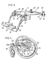
- the wheelchair apparatus primarily comprises four individual and separable units, namely a lifting device 10, a carrier frame 11 mounted on the lifting device 10, a chassis 12 supporting the lifting device 10 and a compressor and battery unit 13 located in a rearwardly opening compartment or reception space 14 in the chassis and releasably connected to the device 10 by a tube 15; together with fittings including armrests 19, a leg-support 16, a backrest 17, a seat 18 and a control handset 13A.
- the compartment is large enough to contain the flank panels 10A employed with the lifting device when the latter, after removal from the chassis and carrier frame, is employed as a bath-lift.
- the device 10 and backrest 17 are generally as described in specification No. GB-A-2166415, and the unit 13 and control handset 13A are generally as described in our co-pending specification No. GB-A-2210411; and the entire contents of these specifications are incorporated herein by reference.
- the carrier frame 11 provides mountings 20 in which the armrests 19 are releasably secured; mountings 21 in which the leg-support 16 is telescopically and releasably supported; brackets 22 providing oppositely directed channels 23 in which elongate formations 23A (e.g. of T-shaped cross-section) of the lateral margins of the platform 24 of the device 10 engage slidably; hooked stops 25 at the front to abut the front end of the platform; and manually displaceable spring retaining clips 26 to releasably engage the rear of the platform.
- elongate formations 23A e.g. of T-shaped cross-section
- the frame 11 serves also as a locating surround for a wedge shaped seat member 27 which extends to overlie a front cross-member 28 of the frame 11, and rests on the platform to support a removable seat cushion 30 in a position in which it inclines forwardly relative to the platform.
- the backrest 17 is attached releasably to mountings 37 on the rear of the platform by spring loaded plunger bolts 38, and the upper part of the backrest is extended to provide a handlebar 39, for an assistant or helper.
- the chassis 12 provides castor mountings 40 for small front castor wheels 41; quick release rear axle mountings 42 for a pair of large rear wheels 43 having hand rims 44; four pads 45 to support centre portions of the suckers 31 of the device 10 and four abutments 45A to locate or support the base 32 of the device 10, together with a pair of top flanged locking levers 46 actuable by a manually actuable lever 47 and an over-centre mechanism 46A (FIGURES 8 and 9) to lock the base 32 onto an upper frame portion 48 of the chassis; and a lower frame portion 49 projecting rearwards to serve as a foot-bar for a helper to tread on to tilt the wheelchair.
- the compartment or reception space 14 is disposed between the frame portions 48 and 49.
- the leg support 16 includes two foot rests 33 carried on pivot arms 34 so as to be pivotable upwards, from the positions illustrated, to out-of-use positions; and the arms 34 are mounted on a member 35 engaged telescopically in lower portions 36 of the mountings.
- FIGURES 1 AND 3 these lower portions 36 may be detachable to permit a pivotable leg-support 16A to be fitted as indicated in broken lines in FIGURE 1.
- the support 16A comprises a frame 50 pivotally hung upon the mountings 21; a leg panel 51 mounted on the frame 50 to be releasable for sliding adjustment of the position of a footrest 52 relative to the seat; and a linkage 53 pivotally interconnected between the chassis and the frame 50, to swing the frame 50 upwards relative to the seat as the latter is lowered.
- a leg support of the kind disclosed in specification No. GB-A-2207042 (which is incorporated herein by reference) may be substituted for the support 16A.
- the lower portions 36 may be pivotally and detachably mounted on pivots 54 provided on the frame 11; and have manually operable catches 55 to lock the legrests in the working position shown in the drawings. When the catches are released the legrests can be swung outwards clear of the front of the seat, and, if desired, lifted off the pivots 54 and removed from the apparatus.
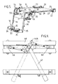
- FIGURE 5 also shows plunger catches 56 for retaining the armrests 19 in the sockets 20; a simple seat panel 29 (instead of the wedge shaped seat member 27) to support a wedge shaped form of the cushion; and a retaining hook 60.
- FIGURE 6 shows the front part of one armrest 19 in detail, to reveal a further plunger catch 57 for retaining a tray or table support in a socket 58 provided by each armrest, and a mounting 59 into which the handset 13A clips.
- the braking apparatus comprises a pair of wheel brakes 61, a manually actuable control mechanism 62 and an automatic actuating mechanism 63.
- the brakes 61 include a braking member 64, for each wheel 43, adjustably mounted on a respective arm 65, which arms are pivotally mounted on the portion 48 and are linked by a shaft 69 and levers 71 to move in unison about a brake axis 66 between a "brakes-on" position (FIGURE 11) and a brakes-off" position shown in broken lines in FIGURE 12, as hereinafter described.
- the control mechanism 62 includes an operating lever 67 releasably connected to a control member 68 which is mounted on a shaft 69 carried by the frame so as to be swingable about a control axis co-axial with the shaft to move an actuating pivot 70 about said control axis; and includes a brake actuating lever 71 which is supported by and connects said pivot 70 and a brake pivot 72 mounted on one arm 65 so as to move the brakes between the "on” and “off” positions as the lever 67 is moved between the positions shown in full and broken lines in FIGURE 12.
- the pivot axes are arranged so that as the brakes near the "on" position, the actuating pivot 70 passes directly downwards through the common plane of the control axis and the parallel axis of the brake pivot 72, to give an "over-centre” action for holding the brakes on and an increasing mechanical advantage as the pivot 70 approaches the common plane from the off position.
- control mechanism 62 may be substantially duplicated on the other side of the chassis and connected to the duplicate by a shaft or torque tube which is co-axial with the brake axis 66 and mechanically and directly connects the two arms 65 to move in unison.
- the lever 67 may be releasably securably in a socket in e.g. by means of a locking pin 67A as shown in FIGURE 14, or a duplicate lever may be provided.
- the lever 71 or one thereof, is extended rearwards to carry a roller 73.
- the automatic actuating mechanism 63 includes a hub 78 mounted on the frame, a drum 74 rotatably carried by the hub, a winding spring (not shown) acting between the hub and drum to urge the latter in a clockwise direction indicated by arrow A in FIGURE 11; a pawl 75 pivotally mounted on the drum 74 for movement between an extended position (full lines) and a retracted position (broken lines) as shown in FIGURE 11 (the pawl may be spring biased towards the extended position); and a cord 76 which is wound onto the drum and has an end knob or connector 77 releasably secured to the hook 60 so that as the latter is raised cord is drawn from the drum causing the latter to turn anticlockwise and thereby move the pawl to engage the roller and lift the rear end of the lever 71 from the "off" to the "on” position.
- the arrangement of the braking apparatus, and in particular the relevant axes of parts 72, 69 and 70, is such that when the lever 67 is swung rearwards manually or by the hook 60 being raised sufficiently to fully apply the brakes, the latter remain “on” when and after the hook 60 is lowered, until such time as the lever 67 is manually displaced to the "off" position, in which it is retained by the bias spring 65A. That is to say, the axis 70 passes beyond a line between the axes 72 and 69 as the lever is swung rearwards to a limit provided by the end 71A of the lever 71 being stopped by abutting the shaft 69.
- the ratio of lift to drum rotation is such that only a relatively small amount of lift, e.g. 10 to 15 cm of a possible 30 to 50 cm of maximum lift, is required to bring the lever automatically to the stable fully on position so that further lifting carries the pawl anticlockwise past and below the raised roller.
- the spring-driven rotation of the drum causes the cord to be re-wound, and the pawl swings to the retracted position as it strikes and passes the roller so as not to hinder winding of the cord.
- the apparatus could be arranged so that the brakes are released as the hook 60 is lowered, e.g.
- the mechanism 63 is enclosed in a cover 79 which acts as a stop abutted by the knobs 77 when the knob is disengaged from the hook 60.
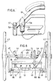
- the lifting device can be employed in the condition shown in FIGURE 10 on its own, e.g. in a bath or on a hard surface to which the suckers 31 can adhere, and for this reason the backrest 17 is preferentially attached to the platform 24 and not to the carrier frame 11.
- the compressor and battery unit 13 is provided with a carrying handle and the pipe 15 and remote hand-control unit 13A are detachable from the unit 13 and from the lifting device and armrest.
- FIGURE 10 also shows a pressure relief valve 80, which releases pressure from the pipe and lifting device when a predetermined pressure is exceeded, which pressure relief valve can be actuated mechanically by a pull-cord 81 which is attached to the rear of the platform by a cleat 82 to cause compressed air to be released when a predetermined height of lift of the platform has been reached.
- the cord is preferably anchored by the cleat at a length which prevents the lifting device being driven to its fullest extent of lift, by a few centimetres, but the cord can be secured to the cleat in positions giving a lesser limit to the lift height, e.g.
- the flank panel 10A has a hinge 83 which connects a mounting 84 to the panel, the mounting 84 being slidably engageable upon the formation 23A to support the panel upon the platform.
- the flank panel is removed, the lifting device is deflated to the minimal condition in which it is shown in FIGURE 10, the base 32 is placed upon the chassis so as to rest against the abutments 45A in positions in which the centres of the suckers rest upon the pads 45, and then the hand lever 47 is swung from the position shown in full lines in FIGURE 9 to the position shown in chain broken lines to pass a locking catch 84 which retains the lever 47 in the latter position.
- the movement of the lever 47 swings the upper ends of the locking levers 46 towards each other to engage over the base 32 to secure the base to the chassis.
- the carrier frame 11 is held in front of the platform and then slid rearwards so that the front ends of the formations 23A enter into the channels 23 as the carrier frame is pushed towards the rear of the platform 24.
- the spring clips 26 are swung to engage the rear of the platform.
- the cord 76 is then drawn upwards from the cover 79 and is looped onto the hook 60 so that the knob prevents retraction of the cord from the frame 11.
- the carrier frame may be applied to the platform with the legrest and armrest in situ if desired, but it is preferred to insert the carrier frame without the seat in position.
- the seat is laid on the panel or seat member and is attached or held in position by a velcro strip or a press-stud fixing, not shown. If desired a restraining belt may be fitted to the lower frame run 85 of the backrest to retain an occupant on the seat.
- the handset unit 13A is then clipped to the armrest mounting 59 and the unit 13 is inserted into the compartment or space 14.
- rollers 86 may be provided on a rear chassis member as shown in FIGURE 8.
- the wheelchair apparatus gives a relatively large maximum to minimum height ratio for the seat whilst retaining all the attributes of a conventional wheelchair.
- the lifting device may be used at only a minimal lift condition in which the device is pressurised partially by the compressor unit, which may then be switched off, so as to serve as an air suspension for the seat whilst the wheelchair is in motion.
- the apparatus provides increased utility by allowing the lift operating device to be separated from the chassis and carrier frames for use as a bath lift, and in the disassembled condition, especially with the large main wheels removed, the whole apparatus is easily stowed in the luggage space of an ordinary car, and the individual units, being relatively small, are light and easily handled by a person of only moderate strength.
- the automatic brake ensures that the apparatus is only mobile whilst it is in a safe i.e. low lift, condition, and the apparatus provides facilities for a disabled occupant to return the apparatus from a high lift condition to a low lift condition for mobility without requiring, in most cases, assistance by another person.
- the battery is preferably of a rechargeable form and the unit preferably includes a charging socket 88 by means of which the battery can be recharged and compressor operated from an external electricity source.
- the unit 13 preferably includes an on/off switch 87 (FIGURE 8).
Claims (10)
- Appareil de fauteuil roulant, comprenant un châssis monté sur roues (12) auquel est fixé un dispositif élévateur (10) pour faire monter et descendre un siège (18) supporté par un cadre, dans lequel le dispositif élévateur est séparable du châssis (12) et construit de manière à pouvoir être utilisé comme groupe élévateur statique, indépendamment du châssis monté sur roues (12), et comporte une plate-forme (24) sur laquelle une personne peut être assise de façon à pouvoir être soulevée par le dispositif élévateur; et caractérisé en ce que le dispositif élévateur est fixé par serrage au châssis monté sur roues au moyen d'un mécanisme de verrouillage déblocable manuellement (46A), et en ce que le cadre est un cadre porteur détachable (11) qui est fixé de façon amovible à ladite plate-forme (24) et supporté par celle-ci au haut du dispositif élévateur, de manière à être mobile par rapport au châssis monté sur roues.
- Appareil selon la revendication 1, dans lequel le cadre porteur comporte des montures (20) pour des accoudoirs et des montures (21) pour des supports de jambes et présente un emplacement pour le siège (27), tel qu'un coussin, et dans lequel un dossier amovible est monté de façon détachable sur la plate-forme, indépendamment du cadre porteur.
- Appareil selon la revendication 2, dans lequel le cadre porteur (11) s'adapte par glissement sur des profils (23A) formés sur les bords de la plate-forme (24) et comporte des moyens de retenue (26) actionnables annuellement pour maintenir le cadre (11) en place sur la plate-forme (24), au moins un panneau latéral (10A) étant prévu pour pouvoir être mis en place sur l'un ou l'autre desdits profils (23A) lorsque le cadre porteur (11) a été retiré, pour constituer un prolongement articulé de la plate-forme, et dans lequel le cadre porteur (11) ou le châssis (12) comporte un logement pour le rangement du ou des panneaux latéraux (10A).
- Appareil selon l'une quelconque des revendications 1 à 3, dans lequel le mécanisme de verrouillage actionnable manuellement (46, 47) est prévu sur le châssis de façon à assujettir un socle (32) du dispositif élévateur sur des butées (45A) prévues sur le châssis.
- Appareil selon la revendication 4, dans lequel ledit châssis comprend une partie supérieure en forme de cadre (48) sur laquelle lesdites butées (45A) sont prévues.
- Appareil selon la revendication 5, dans lequel ladite partie supérieure en forme de cadre comporte aussi des montures (42) pour des roues principales démontables, ainsi qu'un logement (14) pour un groupe formant pompe à air portable (13) au-dessous de ladite partie en forme de cadre.
- Appareil selon l'une quelconque des revendications 1 à 5, dans lequel le châssis comporte, au-dessous du dispositif élévateur, un compartiment (14) ou autre logement pour un groupe formant pompe à air portable (13) et destiné à alimenter en air sous pression le dispositif élévateur (10), et dans lequel le groupe pompe à air (13) est muni d'une batterie ou d'un élément accumulateur électrique, de manière à former un groupe portable utilisable avec le dispositif élévateur (10) lorsque ce dernier est retiré du châssis, et avec le cadre porteur (11).
- Appareil selon la revendication 6 ou 7, dans lequel le cadre porteur comporte une monture (59) pour une unité de commande manuelle (13A) qui est raccordée de façon détachable au groupe pompe à air portable et commande celui-ci.
- Appareil selon l'une quelconque des revendications 1 à 8, dans lequel le châssis (12) est muni d'un dispositif de freinage comprenant au moins un frein (61) sur roue et un mécanisme d'actionnement automatique (63) réagissant au siège (18), caractérisé en outre en ce que le mécanisme d'actionnement automatique (63) est agencé de manière à être débrayé, rendu inactif ou desserré par un infirmier ou un autre membre du personnel de service, pour permettre que l'appareil soit déplacé alors que le siège (18) est en position haute.
- Appareil selon la revendication 9, dans lequel le mécanisme d'actionnement automatique (63) comprend un élément (76) qui est raccordé de façon détachable à une partie mobile verticalement (60) du siège (18) ou du dispositif élévateur (10).
Priority Applications (1)
| Application Number | Priority Date | Filing Date | Title |
|---|---|---|---|
| AT89309571T ATE83914T1 (de) | 1988-09-29 | 1989-09-20 | Rollstuhlvorrichtung. |
Applications Claiming Priority (4)
| Application Number | Priority Date | Filing Date | Title |
|---|---|---|---|
| GB888822894A GB8822894D0 (en) | 1988-09-29 | 1988-09-29 | Wheelchair apparatus |
| GB8822894 | 1988-09-29 | ||
| GB8901157 | 1989-01-19 | ||
| GB898901157A GB8901157D0 (en) | 1989-01-19 | 1989-01-19 | Wheelchair |
Publications (2)
| Publication Number | Publication Date |
|---|---|
| EP0361774A1 EP0361774A1 (fr) | 1990-04-04 |
| EP0361774B1 true EP0361774B1 (fr) | 1992-12-30 |
Family
ID=26294458
Family Applications (1)
| Application Number | Title | Priority Date | Filing Date |
|---|---|---|---|
| EP89309571A Expired - Lifetime EP0361774B1 (fr) | 1988-09-29 | 1989-09-20 | Dispositif de fauteuil roulant |
Country Status (5)
| Country | Link |
|---|---|
| US (1) | US4993736A (fr) |
| EP (1) | EP0361774B1 (fr) |
| JP (1) | JP2708911B2 (fr) |
| DE (1) | DE68904151T2 (fr) |
| GB (1) | GB2225558B (fr) |
Cited By (1)
| Publication number | Priority date | Publication date | Assignee | Title |
|---|---|---|---|---|
| CN104427911A (zh) * | 2012-03-06 | 2015-03-18 | 运动概念有限公司 | 低轮廓座椅框架 |
Families Citing this family (35)
| Publication number | Priority date | Publication date | Assignee | Title |
|---|---|---|---|---|
| US5209509A (en) * | 1990-05-26 | 1993-05-11 | Gunnell, Inc. | Wheelchair footrest assembly |
| US5209322A (en) * | 1991-04-01 | 1993-05-11 | Mcmahon Robert | Elevated wheelchair device |
| JPH0742424Y2 (ja) * | 1991-05-21 | 1995-10-04 | 株式会社リィツメディカル | 医療検査用車椅子 |
| US5601302A (en) * | 1991-11-07 | 1997-02-11 | Board Of Supervisors Of Louisiana State University And Agricultural And Mechanical College Office Of Technology Transfer | Full access wheelchair |
| US5441466A (en) * | 1994-02-03 | 1995-08-15 | Piaget; Gary | Exercise step with adjustable leg bellows |
| US5669086A (en) * | 1994-07-09 | 1997-09-23 | Mangar International Limited | Inflatable medical lifting devices |
| US5437497A (en) * | 1994-07-11 | 1995-08-01 | Hutson; Kelly | Height adjustable wheelchair seat |
| GB2296429B (en) * | 1994-12-31 | 1998-11-25 | Mangar International Ltd | Lifting apparatus |
| US5695248A (en) * | 1996-07-03 | 1997-12-09 | Bell; Dale A. | Retrofit adjustable seat |
| GB2317335B (en) | 1996-09-06 | 2000-07-12 | Mangar International Ltd | Lifting seat apparatus for use in a bath |
| US6113188A (en) * | 1997-12-24 | 2000-09-05 | Stewart; Robert V. | Portable seating assist device |
| US6467785B2 (en) | 1998-07-20 | 2002-10-22 | Tony Toppses | Wheelchair with adjustable seat |
| CH693700A5 (fr) * | 1999-12-06 | 2003-12-31 | Yves Birbaum | Fauteuil roulant manuel. |
| US6871364B1 (en) * | 2000-04-21 | 2005-03-29 | Thomas Leoutsakos | Foot lift |
| US6533358B1 (en) * | 2000-11-10 | 2003-03-18 | Medisol Usa, Inc. | Kit for converting a non-reclining wheelchair into a reclining wheelchair |
| EP1694267A2 (fr) * | 2003-12-17 | 2006-08-30 | DAVIS, David T. | Elevateur pneumatique |
| US7055840B1 (en) * | 2004-11-17 | 2006-06-06 | Kelso Thomas G | Lift wheelchair |
| US20070000048A1 (en) * | 2004-12-16 | 2007-01-04 | Davis David T | Pneumatic lift and method for transferring an invalid patient |
| US20070084648A1 (en) * | 2005-10-14 | 2007-04-19 | Mobilife | Wheelchair having unitized chassis |
| US8267474B2 (en) * | 2005-10-21 | 2012-09-18 | Fetisoff Valentine A | Portable self-contained pneumatic lift chair |
| US20080133089A1 (en) * | 2006-11-30 | 2008-06-05 | Ahmad Bayomy | Height-Adjusting Wheelchair |
| US7594698B1 (en) | 2007-10-17 | 2009-09-29 | Marge Palmer | Portable seat for a wheelchair |
| US7909404B2 (en) * | 2008-05-20 | 2011-03-22 | Caterpillar Inc. | Independent height adjustment system for a seat assembly and machine using same |
| US20100038880A1 (en) * | 2008-08-15 | 2010-02-18 | Bagg Christian Peter Edward | Modular and/or configurable wheelchair apparatus |
| US20100244400A1 (en) * | 2009-03-30 | 2010-09-30 | Maor Ben-Hammo | Method and system for disposal of waste |
| JP5523037B2 (ja) * | 2009-09-28 | 2014-06-18 | ピジョン株式会社 | 車椅子 |
| US8413277B2 (en) * | 2009-10-13 | 2013-04-09 | Woodlark Circle, Inc. | Pneumatic lift with unidirectional valve |
| DE102010021493A1 (de) * | 2010-05-26 | 2011-12-01 | Ferdinand Lusch Gmbh & Co Kg | Möbel zur Verstellung in eine Aufstehhilfsposition |
| CA2806049A1 (fr) * | 2013-02-18 | 2014-08-18 | Jason Mills | Dispositif de levage de plancher pneumatique comportant une planche de transfert |
| US9351890B2 (en) | 2013-03-15 | 2016-05-31 | Stryker Corporation | Medical support apparatus |
| CH706250B1 (de) * | 2013-04-02 | 2013-09-30 | Hanspeter Abegg | Vorrichtung zum Heben und Verschieben von Objekten. |
| US20150202102A1 (en) * | 2014-01-20 | 2015-07-23 | Anita Dunham | Wheelchair with Automatic Seat Lift Mechanism |
| US10080438B2 (en) | 2015-09-21 | 2018-09-25 | Stryker Corporation | Patient support apparatus |
| CN109532579A (zh) * | 2019-01-19 | 2019-03-29 | 海安荣民汽车配件有限公司 | 舒适型升降汽车座椅 |
| KR102351407B1 (ko) * | 2020-06-10 | 2022-01-19 | 서울대학교병원 | 리프트용 방석 및 이를 포함하는 휠체어 높낮이 조절 장치 |
Family Cites Families (13)
| Publication number | Priority date | Publication date | Assignee | Title |
|---|---|---|---|---|
| US3123400A (en) * | 1964-03-03 | Invalid s chair | ||
| US3103384A (en) * | 1961-01-23 | 1963-09-10 | Edwin L Zivi | Adjustable and convertible wheel chair |
| US3295621A (en) * | 1963-04-25 | 1967-01-03 | Dentists Supply Co | Supporting base for chair and the like for gliding on a film of air |
| SE417275B (sv) * | 1978-11-16 | 1981-03-09 | Per Gotthold Bergman | Isertagbar rullstol |
| GB2110527B (en) * | 1981-04-29 | 1984-12-19 | David Edmund Talbot Garman | Apparatus for supporting disabled persons |
| GB2097250B (en) * | 1981-04-29 | 1985-02-27 | Garman David Edmund Talbot | Apparatus for supporting disabled persons |
| DE3119867A1 (de) * | 1981-05-19 | 1982-12-16 | Harry 7311 Hochdorf Apprich | Hoehenverstellbarer sitz |
| US4538854A (en) * | 1982-12-13 | 1985-09-03 | Morette's Limited | Elevator chair |
| GB2166415B (en) * | 1984-11-06 | 1988-10-12 | Mangar Aids Ltd | Lifting apparatus |
| GB8715149D0 (en) * | 1987-06-27 | 1987-08-05 | Payne J C | Wheelchair |
| GB8717292D0 (en) * | 1987-07-22 | 1987-08-26 | Mangar Aids Ltd | Supports for disabled persons |
| US4862997A (en) * | 1987-09-14 | 1989-09-05 | Eberle Kenneth F | Wheel chair with elevating seat having a high lift capability |
| GB2210411B (en) * | 1987-09-30 | 1992-05-27 | Mangar Aids Ltd | Improvements in or relating to compressed air supply apparatus |
-
1989
- 1989-09-20 EP EP89309571A patent/EP0361774B1/fr not_active Expired - Lifetime
- 1989-09-20 GB GB8921277A patent/GB2225558B/en not_active Expired
- 1989-09-20 DE DE8989309571T patent/DE68904151T2/de not_active Expired - Lifetime
- 1989-09-22 US US07/411,395 patent/US4993736A/en not_active Expired - Fee Related
- 1989-09-29 JP JP1252537A patent/JP2708911B2/ja not_active Expired - Lifetime
Cited By (2)
| Publication number | Priority date | Publication date | Assignee | Title |
|---|---|---|---|---|
| CN104427911A (zh) * | 2012-03-06 | 2015-03-18 | 运动概念有限公司 | 低轮廓座椅框架 |
| CN104427911B (zh) * | 2012-03-06 | 2017-07-25 | 运动概念有限公司 | 低轮廓座椅框架 |
Also Published As
| Publication number | Publication date |
|---|---|
| US4993736A (en) | 1991-02-19 |
| GB8921277D0 (en) | 1989-11-08 |
| GB2225558B (en) | 1992-07-29 |
| DE68904151T2 (de) | 1993-07-29 |
| EP0361774A1 (fr) | 1990-04-04 |
| JPH02124158A (ja) | 1990-05-11 |
| GB2225558A (en) | 1990-06-06 |
| DE68904151D1 (de) | 1993-02-11 |
| JP2708911B2 (ja) | 1998-02-04 |
Similar Documents
| Publication | Publication Date | Title |
|---|---|---|
| EP0361774B1 (fr) | Dispositif de fauteuil roulant | |
| US5050695A (en) | Power attachment for wheelchair | |
| US4999862A (en) | Wheelchair mounted invalid lift | |
| US4354791A (en) | Wheelchair construction | |
| US4738581A (en) | Vehicle mounted wheelchair carrier | |
| US8646124B2 (en) | Transport apparatus | |
| US6766871B2 (en) | Attachment means for attaching a wheelchair to a motorized apparatus | |
| CA1233100A (fr) | Poussette pour les enfants | |
| US5255934A (en) | Wheelchair seat convertible to toilet seat | |
| US6427263B1 (en) | Device for moving patients | |
| US4266305A (en) | Wheelchair for transportation vehicles | |
| US4744578A (en) | User inclinable prone stander type wheelchair | |
| CA2190014C (fr) | Appareil de musculation pour handicapes | |
| US6257609B1 (en) | Tilt-in-space wheelchair | |
| US8696017B2 (en) | Chair with a height-adjustable seat | |
| WO2006045316A1 (fr) | Fauteuil roulant confortable | |
| GB2113160A (en) | Improvements in foldable wheelchairs | |
| GB2300845A (en) | Apparatus for Assisting the Movement of Disabled Persons | |
| EP0067069A1 (fr) | Fauteuils pour invalides | |
| GB2069969A (en) | Wheelchairs | |
| GB2048791A (en) | Wheelchairs | |
| US5058221A (en) | Combination of a wheelchair and a transport device for transporting a patient | |
| GB2097250A (en) | Apparatus for supporting disabled persons | |
| WO1994027545A1 (fr) | Voiture a roues conçue notamment pour transporter un enfant en bas age ou un invalide | |
| US6533523B2 (en) | Wheelchair system for transferring occupant to motor vehicle |
Legal Events
| Date | Code | Title | Description |
|---|---|---|---|
| PUAI | Public reference made under article 153(3) epc to a published international application that has entered the european phase |
Free format text: ORIGINAL CODE: 0009012 |
|
| AK | Designated contracting states |
Kind code of ref document: A1 Designated state(s): AT BE CH DE ES FR GB GR IT LI LU NL SE |
|
| 17P | Request for examination filed |
Effective date: 19900928 |
|
| 17Q | First examination report despatched |
Effective date: 19911212 |
|
| GRAA | (expected) grant |
Free format text: ORIGINAL CODE: 0009210 |
|
| AK | Designated contracting states |
Kind code of ref document: B1 Designated state(s): AT BE CH DE ES FR GR IT LI LU NL SE |
|
| PG25 | Lapsed in a contracting state [announced via postgrant information from national office to epo] |
Ref country code: AT Effective date: 19921230 Ref country code: IT Free format text: LAPSE BECAUSE OF FAILURE TO SUBMIT A TRANSLATION OF THE DESCRIPTION OR TO PAY THE FEE WITHIN THE PRE;WARNING: LAPSES OF ITALIAN PATENTS WITH EFFECTIVE DATE BEFORE 2007 MAY HAVE OCCURRED AT ANY TIME BEFORE 2007. THE CORRECT EFFECTIVE DATE MAY BE DIFFERENT FROM THE ONE RECORDED.SCRIBED TIME-LIMIT Effective date: 19921230 Ref country code: ES Free format text: THE PATENT HAS BEEN ANNULLED BY A DECISION OF A NATIONAL AUTHORITY Effective date: 19921230 Ref country code: FR Effective date: 19921230 Ref country code: SE Effective date: 19921230 Ref country code: CH Effective date: 19921230 Ref country code: NL Effective date: 19921230 Ref country code: GR Free format text: LAPSE BECAUSE OF FAILURE TO SUBMIT A TRANSLATION OF THE DESCRIPTION OR TO PAY THE FEE WITHIN THE PRESCRIBED TIME-LIMIT Effective date: 19921230 Ref country code: LI Effective date: 19921230 Ref country code: BE Effective date: 19921230 |
|
| REF | Corresponds to: |
Ref document number: 83914 Country of ref document: AT Date of ref document: 19930115 Kind code of ref document: T |
|
| REF | Corresponds to: |
Ref document number: 68904151 Country of ref document: DE Date of ref document: 19930211 |
|
| REG | Reference to a national code |
Ref country code: CH Ref legal event code: PL |
|
| EN | Fr: translation not filed | ||
| NLV1 | Nl: lapsed or annulled due to failure to fulfill the requirements of art. 29p and 29m of the patents act | ||
| PG25 | Lapsed in a contracting state [announced via postgrant information from national office to epo] |
Ref country code: LU Free format text: LAPSE BECAUSE OF NON-PAYMENT OF DUE FEES Effective date: 19930930 |
|
| PLBE | No opposition filed within time limit |
Free format text: ORIGINAL CODE: 0009261 |
|
| STAA | Information on the status of an ep patent application or granted ep patent |
Free format text: STATUS: NO OPPOSITION FILED WITHIN TIME LIMIT |
|
| PGFP | Annual fee paid to national office [announced via postgrant information from national office to epo] |
Ref country code: DE Payment date: 19931129 Year of fee payment: 5 |
|
| 26N | No opposition filed | ||
| PG25 | Lapsed in a contracting state [announced via postgrant information from national office to epo] |
Ref country code: DE Effective date: 19950601 |