EP0360941A2 - Decompostion of volatile organic halogenated compounds contained in gases and aqueous solutions - Google Patents
Decompostion of volatile organic halogenated compounds contained in gases and aqueous solutions Download PDFInfo
- Publication number
- EP0360941A2 EP0360941A2 EP88309759A EP88309759A EP0360941A2 EP 0360941 A2 EP0360941 A2 EP 0360941A2 EP 88309759 A EP88309759 A EP 88309759A EP 88309759 A EP88309759 A EP 88309759A EP 0360941 A2 EP0360941 A2 EP 0360941A2
- Authority
- EP
- European Patent Office
- Prior art keywords
- ozone
- compounds
- adsorbent bed
- gases
- volatile organic
- Prior art date
- Legal status (The legal status is an assumption and is not a legal conclusion. Google has not performed a legal analysis and makes no representation as to the accuracy of the status listed.)
- Granted
Links
- 150000001875 compounds Chemical class 0.000 title claims abstract description 92
- 239000007789 gas Substances 0.000 title claims abstract description 86
- 239000007864 aqueous solution Substances 0.000 title claims abstract description 25
- VYPSYNLAJGMNEJ-UHFFFAOYSA-N Silicium dioxide Chemical compound O=[Si]=O VYPSYNLAJGMNEJ-UHFFFAOYSA-N 0.000 claims abstract description 86
- CBENFWSGALASAD-UHFFFAOYSA-N Ozone Chemical compound [O-][O+]=O CBENFWSGALASAD-UHFFFAOYSA-N 0.000 claims abstract description 75
- 229910002027 silica gel Inorganic materials 0.000 claims abstract description 66
- 239000000741 silica gel Substances 0.000 claims abstract description 66
- 239000000243 solution Substances 0.000 claims abstract description 39
- 239000003463 adsorbent Substances 0.000 claims abstract description 38
- 230000001678 irradiating effect Effects 0.000 claims abstract description 17
- 238000000034 method Methods 0.000 claims abstract description 15
- 239000012855 volatile organic compound Substances 0.000 claims abstract description 10
- 238000001784 detoxification Methods 0.000 claims description 78
- XLYOFNOQVPJJNP-UHFFFAOYSA-N water Substances O XLYOFNOQVPJJNP-UHFFFAOYSA-N 0.000 claims description 57
- 238000000354 decomposition reaction Methods 0.000 claims description 17
- 239000000203 mixture Substances 0.000 claims description 16
- 239000010453 quartz Substances 0.000 claims description 12
- 150000002894 organic compounds Chemical class 0.000 claims description 11
- 238000006243 chemical reaction Methods 0.000 claims description 8
- 238000010438 heat treatment Methods 0.000 claims description 7
- 230000009467 reduction Effects 0.000 claims description 6
- 230000005855 radiation Effects 0.000 claims description 2
- 238000004064 recycling Methods 0.000 claims description 2
- 239000002250 absorbent Substances 0.000 claims 1
- 230000002745 absorbent Effects 0.000 claims 1
- UBOXGVDOUJQMTN-UHFFFAOYSA-N trichloroethylene Natural products ClCC(Cl)Cl UBOXGVDOUJQMTN-UHFFFAOYSA-N 0.000 description 67
- XSTXAVWGXDQKEL-UHFFFAOYSA-N Trichloroethylene Chemical group ClC=C(Cl)Cl XSTXAVWGXDQKEL-UHFFFAOYSA-N 0.000 description 64
- 229960001866 silicon dioxide Drugs 0.000 description 60
- YMWUJEATGCHHMB-UHFFFAOYSA-N Dichloromethane Chemical compound ClCCl YMWUJEATGCHHMB-UHFFFAOYSA-N 0.000 description 36
- 238000012360 testing method Methods 0.000 description 34
- ISWSIDIOOBJBQZ-UHFFFAOYSA-N Phenol Chemical compound OC1=CC=CC=C1 ISWSIDIOOBJBQZ-UHFFFAOYSA-N 0.000 description 28
- 238000002474 experimental method Methods 0.000 description 28
- 230000003647 oxidation Effects 0.000 description 27
- 238000007254 oxidation reaction Methods 0.000 description 27
- 235000012239 silicon dioxide Nutrition 0.000 description 15
- 239000002351 wastewater Substances 0.000 description 14
- 230000001965 increasing effect Effects 0.000 description 12
- 229940073584 methylene chloride Drugs 0.000 description 12
- IJGRMHOSHXDMSA-UHFFFAOYSA-N Atomic nitrogen Chemical compound N#N IJGRMHOSHXDMSA-UHFFFAOYSA-N 0.000 description 11
- BZHJMEDXRYGGRV-UHFFFAOYSA-N Vinyl chloride Chemical compound ClC=C BZHJMEDXRYGGRV-UHFFFAOYSA-N 0.000 description 11
- 229960002415 trichloroethylene Drugs 0.000 description 10
- 230000003028 elevating effect Effects 0.000 description 9
- 239000011521 glass Substances 0.000 description 8
- 230000000694 effects Effects 0.000 description 7
- 229960005419 nitrogen Drugs 0.000 description 7
- 231100000331 toxic Toxicity 0.000 description 7
- 230000002588 toxic effect Effects 0.000 description 7
- BDAGIHXWWSANSR-UHFFFAOYSA-N methanoic acid Natural products OC=O BDAGIHXWWSANSR-UHFFFAOYSA-N 0.000 description 6
- VLKZOEOYAKHREP-UHFFFAOYSA-N n-Hexane Chemical compound CCCCCC VLKZOEOYAKHREP-UHFFFAOYSA-N 0.000 description 6
- 125000005608 naphthenic acid group Chemical group 0.000 description 5
- 231100000167 toxic agent Toxicity 0.000 description 5
- QPFMBZIOSGYJDE-UHFFFAOYSA-N 1,1,2,2-tetrachloroethane Chemical compound ClC(Cl)C(Cl)Cl QPFMBZIOSGYJDE-UHFFFAOYSA-N 0.000 description 4
- GATVIKZLVQHOMN-UHFFFAOYSA-N Chlorodibromomethane Chemical compound ClC(Br)Br GATVIKZLVQHOMN-UHFFFAOYSA-N 0.000 description 4
- QVGXLLKOCUKJST-UHFFFAOYSA-N atomic oxygen Chemical compound [O] QVGXLLKOCUKJST-UHFFFAOYSA-N 0.000 description 4
- DIKBFYAXUHHXCS-UHFFFAOYSA-N bromoform Chemical compound BrC(Br)Br DIKBFYAXUHHXCS-UHFFFAOYSA-N 0.000 description 4
- GZUXJHMPEANEGY-UHFFFAOYSA-N bromomethane Chemical compound BrC GZUXJHMPEANEGY-UHFFFAOYSA-N 0.000 description 4
- 229910052799 carbon Inorganic materials 0.000 description 4
- 239000003610 charcoal Substances 0.000 description 4
- MVPPADPHJFYWMZ-UHFFFAOYSA-N chlorobenzene Chemical compound ClC1=CC=CC=C1 MVPPADPHJFYWMZ-UHFFFAOYSA-N 0.000 description 4
- NEHMKBQYUWJMIP-UHFFFAOYSA-N chloromethane Chemical compound ClC NEHMKBQYUWJMIP-UHFFFAOYSA-N 0.000 description 4
- 229910052681 coesite Inorganic materials 0.000 description 4
- 229910052906 cristobalite Inorganic materials 0.000 description 4
- 229940117389 dichlorobenzene Drugs 0.000 description 4
- 229910052757 nitrogen Inorganic materials 0.000 description 4
- 239000001301 oxygen Substances 0.000 description 4
- 229910052760 oxygen Inorganic materials 0.000 description 4
- 239000000377 silicon dioxide Substances 0.000 description 4
- 229910052682 stishovite Inorganic materials 0.000 description 4
- VZGDMQKNWNREIO-UHFFFAOYSA-N tetrachloromethane Chemical compound ClC(Cl)(Cl)Cl VZGDMQKNWNREIO-UHFFFAOYSA-N 0.000 description 4
- 229910052905 tridymite Inorganic materials 0.000 description 4
- OSWFIVFLDKOXQC-UHFFFAOYSA-N 4-(3-methoxyphenyl)aniline Chemical compound COC1=CC=CC(C=2C=CC(N)=CC=2)=C1 OSWFIVFLDKOXQC-UHFFFAOYSA-N 0.000 description 3
- 241000894006 Bacteria Species 0.000 description 3
- OKTJSMMVPCPJKN-UHFFFAOYSA-N Carbon Chemical compound [C] OKTJSMMVPCPJKN-UHFFFAOYSA-N 0.000 description 3
- WSFSSNUMVMOOMR-UHFFFAOYSA-N Formaldehyde Chemical compound O=C WSFSSNUMVMOOMR-UHFFFAOYSA-N 0.000 description 3
- KFZMGEQAYNKOFK-UHFFFAOYSA-N Isopropanol Chemical compound CC(C)O KFZMGEQAYNKOFK-UHFFFAOYSA-N 0.000 description 3
- MUBZPKHOEPUJKR-UHFFFAOYSA-N Oxalic acid Chemical compound OC(=O)C(O)=O MUBZPKHOEPUJKR-UHFFFAOYSA-N 0.000 description 3
- KRKNYBCHXYNGOX-UHFFFAOYSA-N citric acid Chemical compound OC(=O)CC(O)(C(O)=O)CC(O)=O KRKNYBCHXYNGOX-UHFFFAOYSA-N 0.000 description 3
- 229910001873 dinitrogen Inorganic materials 0.000 description 3
- 235000019253 formic acid Nutrition 0.000 description 3
- BAUYGSIQEAFULO-UHFFFAOYSA-L iron(2+) sulfate (anhydrous) Chemical compound [Fe+2].[O-]S([O-])(=O)=O BAUYGSIQEAFULO-UHFFFAOYSA-L 0.000 description 3
- 229910000359 iron(II) sulfate Inorganic materials 0.000 description 3
- 239000003973 paint Substances 0.000 description 3
- 238000000746 purification Methods 0.000 description 3
- 229920006395 saturated elastomer Polymers 0.000 description 3
- PPKPKFIWDXDAGC-NSCUHMNNSA-N (e)-1,2-dichloroprop-1-ene Chemical group C\C(Cl)=C/Cl PPKPKFIWDXDAGC-NSCUHMNNSA-N 0.000 description 2
- SCYULBFZEHDVBN-UHFFFAOYSA-N 1,1-Dichloroethane Chemical compound CC(Cl)Cl SCYULBFZEHDVBN-UHFFFAOYSA-N 0.000 description 2
- LGXVIGDEPROXKC-UHFFFAOYSA-N 1,1-dichloroethene Chemical group ClC(Cl)=C LGXVIGDEPROXKC-UHFFFAOYSA-N 0.000 description 2
- PAAZPARNPHGIKF-UHFFFAOYSA-N 1,2-dibromoethane Chemical compound BrCCBr PAAZPARNPHGIKF-UHFFFAOYSA-N 0.000 description 2
- KNKRKFALVUDBJE-UHFFFAOYSA-N 1,2-dichloropropane Chemical compound CC(Cl)CCl KNKRKFALVUDBJE-UHFFFAOYSA-N 0.000 description 2
- NLXGURFLBLRZRO-UHFFFAOYSA-N 1-chloro-2-(2-chloroethoxymethoxy)ethane Chemical compound ClCCOCOCCCl NLXGURFLBLRZRO-UHFFFAOYSA-N 0.000 description 2
- BULHJTXRZFEUDQ-UHFFFAOYSA-N 2-chloro-2-(2-chloropropan-2-yloxy)propane Chemical compound CC(C)(Cl)OC(C)(C)Cl BULHJTXRZFEUDQ-UHFFFAOYSA-N 0.000 description 2
- REEBWSYYNPPSKV-UHFFFAOYSA-N 3-[(4-formylphenoxy)methyl]thiophene-2-carbonitrile Chemical compound C1=CC(C=O)=CC=C1OCC1=C(C#N)SC=C1 REEBWSYYNPPSKV-UHFFFAOYSA-N 0.000 description 2
- ZNSMNVMLTJELDZ-UHFFFAOYSA-N Bis(2-chloroethyl)ether Chemical compound ClCCOCCCl ZNSMNVMLTJELDZ-UHFFFAOYSA-N 0.000 description 2
- 241001052209 Cylinder Species 0.000 description 2
- PXHVJJICTQNCMI-UHFFFAOYSA-N Nickel Chemical compound [Ni] PXHVJJICTQNCMI-UHFFFAOYSA-N 0.000 description 2
- CYTYCFOTNPOANT-UHFFFAOYSA-N Perchloroethylene Chemical group ClC(Cl)=C(Cl)Cl CYTYCFOTNPOANT-UHFFFAOYSA-N 0.000 description 2
- 230000009471 action Effects 0.000 description 2
- 150000001298 alcohols Chemical class 0.000 description 2
- XAGFODPZIPBFFR-UHFFFAOYSA-N aluminium Chemical compound [Al] XAGFODPZIPBFFR-UHFFFAOYSA-N 0.000 description 2
- 229910052782 aluminium Inorganic materials 0.000 description 2
- HRQGCQVOJVTVLU-UHFFFAOYSA-N bis(chloromethyl) ether Chemical compound ClCOCCl HRQGCQVOJVTVLU-UHFFFAOYSA-N 0.000 description 2
- XNNQFQFUQLJSQT-UHFFFAOYSA-N bromo(trichloro)methane Chemical compound ClC(Cl)(Cl)Br XNNQFQFUQLJSQT-UHFFFAOYSA-N 0.000 description 2
- 229950005228 bromoform Drugs 0.000 description 2
- 239000003054 catalyst Substances 0.000 description 2
- WQJDQHSMWRYTJX-UHFFFAOYSA-N chloroform;1,2-dichlorobenzene Chemical compound ClC(Cl)Cl.ClC1=CC=CC=C1Cl WQJDQHSMWRYTJX-UHFFFAOYSA-N 0.000 description 2
- 239000012141 concentrate Substances 0.000 description 2
- 230000006378 damage Effects 0.000 description 2
- 238000013461 design Methods 0.000 description 2
- UMNKXPULIDJLSU-UHFFFAOYSA-N dichlorofluoromethane Chemical compound FC(Cl)Cl UMNKXPULIDJLSU-UHFFFAOYSA-N 0.000 description 2
- 229940099364 dichlorofluoromethane Drugs 0.000 description 2
- 235000014113 dietary fatty acids Nutrition 0.000 description 2
- 239000003651 drinking water Substances 0.000 description 2
- 230000005670 electromagnetic radiation Effects 0.000 description 2
- 229930195729 fatty acid Natural products 0.000 description 2
- 239000000194 fatty acid Substances 0.000 description 2
- 150000004665 fatty acids Chemical class 0.000 description 2
- 239000008246 gaseous mixture Substances 0.000 description 2
- VHHHONWQHHHLTI-UHFFFAOYSA-N hexachloroethane Chemical compound ClC(Cl)(Cl)C(Cl)(Cl)Cl VHHHONWQHHHLTI-UHFFFAOYSA-N 0.000 description 2
- 229940102396 methyl bromide Drugs 0.000 description 2
- 229940050176 methyl chloride Drugs 0.000 description 2
- 238000002156 mixing Methods 0.000 description 2
- 238000012986 modification Methods 0.000 description 2
- 230000004048 modification Effects 0.000 description 2
- SNMVRZFUUCLYTO-UHFFFAOYSA-N n-propyl chloride Chemical compound CCCCl SNMVRZFUUCLYTO-UHFFFAOYSA-N 0.000 description 2
- IZUPBVBPLAPZRR-UHFFFAOYSA-N pentachlorophenol Chemical compound OC1=C(Cl)C(Cl)=C(Cl)C(Cl)=C1Cl IZUPBVBPLAPZRR-UHFFFAOYSA-N 0.000 description 2
- 230000008929 regeneration Effects 0.000 description 2
- 238000011069 regeneration method Methods 0.000 description 2
- 239000000126 substance Substances 0.000 description 2
- 229950011008 tetrachloroethylene Drugs 0.000 description 2
- KFUSEUYYWQURPO-OWOJBTEDSA-N trans-1,2-dichloroethene Chemical group Cl\C=C\Cl KFUSEUYYWQURPO-OWOJBTEDSA-N 0.000 description 2
- CYRMSUTZVYGINF-UHFFFAOYSA-N trichlorofluoromethane Chemical compound FC(Cl)(Cl)Cl CYRMSUTZVYGINF-UHFFFAOYSA-N 0.000 description 2
- 229940029284 trichlorofluoromethane Drugs 0.000 description 2
- VYZAMTAEIAYCRO-UHFFFAOYSA-N Chromium Chemical compound [Cr] VYZAMTAEIAYCRO-UHFFFAOYSA-N 0.000 description 1
- RYGMFSIKBFXOCR-UHFFFAOYSA-N Copper Chemical compound [Cu] RYGMFSIKBFXOCR-UHFFFAOYSA-N 0.000 description 1
- KCXVZYZYPLLWCC-UHFFFAOYSA-N EDTA Chemical compound OC(=O)CN(CC(O)=O)CCN(CC(O)=O)CC(O)=O KCXVZYZYPLLWCC-UHFFFAOYSA-N 0.000 description 1
- HCHKCACWOHOZIP-UHFFFAOYSA-N Zinc Chemical compound [Zn] HCHKCACWOHOZIP-UHFFFAOYSA-N 0.000 description 1
- 238000003915 air pollution Methods 0.000 description 1
- 125000001931 aliphatic group Chemical group 0.000 description 1
- 230000001580 bacterial effect Effects 0.000 description 1
- 235000012206 bottled water Nutrition 0.000 description 1
- FMWLUWPQPKEARP-UHFFFAOYSA-N bromodichloromethane Chemical compound ClC(Cl)Br FMWLUWPQPKEARP-UHFFFAOYSA-N 0.000 description 1
- HKPHPIREJKHECO-UHFFFAOYSA-N butachlor Chemical compound CCCCOCN(C(=O)CCl)C1=C(CC)C=CC=C1CC HKPHPIREJKHECO-UHFFFAOYSA-N 0.000 description 1
- 239000006227 byproduct Substances 0.000 description 1
- 229910052793 cadmium Inorganic materials 0.000 description 1
- BDOSMKKIYDKNTQ-UHFFFAOYSA-N cadmium atom Chemical compound [Cd] BDOSMKKIYDKNTQ-UHFFFAOYSA-N 0.000 description 1
- 238000003421 catalytic decomposition reaction Methods 0.000 description 1
- 230000003197 catalytic effect Effects 0.000 description 1
- 238000001311 chemical methods and process Methods 0.000 description 1
- HRYZWHHZPQKTII-UHFFFAOYSA-N chloroethane Chemical compound CCCl HRYZWHHZPQKTII-UHFFFAOYSA-N 0.000 description 1
- 229910052804 chromium Inorganic materials 0.000 description 1
- 239000011651 chromium Substances 0.000 description 1
- 239000000470 constituent Substances 0.000 description 1
- 229910052802 copper Inorganic materials 0.000 description 1
- 239000010949 copper Substances 0.000 description 1
- 125000004122 cyclic group Chemical group 0.000 description 1
- -1 dichloro dichlorobromomethane Chemical compound 0.000 description 1
- 238000009792 diffusion process Methods 0.000 description 1
- 239000006185 dispersion Substances 0.000 description 1
- 235000020188 drinking water Nutrition 0.000 description 1
- 238000005108 dry cleaning Methods 0.000 description 1
- 230000007613 environmental effect Effects 0.000 description 1
- 229960003750 ethyl chloride Drugs 0.000 description 1
- 239000006260 foam Substances 0.000 description 1
- JLYXXMFPNIAWKQ-GNIYUCBRSA-N gamma-hexachlorocyclohexane Chemical compound Cl[C@H]1[C@H](Cl)[C@@H](Cl)[C@@H](Cl)[C@H](Cl)[C@H]1Cl JLYXXMFPNIAWKQ-GNIYUCBRSA-N 0.000 description 1
- JLYXXMFPNIAWKQ-UHFFFAOYSA-N gamma-hexachlorocyclohexane Natural products ClC1C(Cl)C(Cl)C(Cl)C(Cl)C1Cl JLYXXMFPNIAWKQ-UHFFFAOYSA-N 0.000 description 1
- 238000004817 gas chromatography Methods 0.000 description 1
- 239000000499 gel Substances 0.000 description 1
- 239000011491 glass wool Substances 0.000 description 1
- CKAPSXZOOQJIBF-UHFFFAOYSA-N hexachlorobenzene Chemical compound ClC1=C(Cl)C(Cl)=C(Cl)C(Cl)=C1Cl CKAPSXZOOQJIBF-UHFFFAOYSA-N 0.000 description 1
- 239000003295 industrial effluent Substances 0.000 description 1
- 229960002809 lindane Drugs 0.000 description 1
- 239000000463 material Substances 0.000 description 1
- 229910052759 nickel Inorganic materials 0.000 description 1
- 235000006408 oxalic acid Nutrition 0.000 description 1
- 238000006385 ozonation reaction Methods 0.000 description 1
- 150000003071 polychlorinated biphenyls Chemical class 0.000 description 1
- 239000000047 product Substances 0.000 description 1
- 229920002379 silicone rubber Polymers 0.000 description 1
- 239000004945 silicone rubber Substances 0.000 description 1
- 239000002904 solvent Substances 0.000 description 1
- 238000001179 sorption measurement Methods 0.000 description 1
- 229910001220 stainless steel Inorganic materials 0.000 description 1
- 239000010935 stainless steel Substances 0.000 description 1
- 238000006467 substitution reaction Methods 0.000 description 1
- 239000002341 toxic gas Substances 0.000 description 1
- 231100000419 toxicity Toxicity 0.000 description 1
- 230000001988 toxicity Effects 0.000 description 1
- 238000009834 vaporization Methods 0.000 description 1
- 230000008016 vaporization Effects 0.000 description 1
- 238000005406 washing Methods 0.000 description 1
- 235000020681 well water Nutrition 0.000 description 1
- 239000002349 well water Substances 0.000 description 1
- 239000011701 zinc Substances 0.000 description 1
- 229910052725 zinc Inorganic materials 0.000 description 1
Images


Classifications
-
- C—CHEMISTRY; METALLURGY
- C02—TREATMENT OF WATER, WASTE WATER, SEWAGE, OR SLUDGE
- C02F—TREATMENT OF WATER, WASTE WATER, SEWAGE, OR SLUDGE
- C02F1/00—Treatment of water, waste water, or sewage
- C02F1/72—Treatment of water, waste water, or sewage by oxidation
- C02F1/78—Treatment of water, waste water, or sewage by oxidation with ozone
-
- A—HUMAN NECESSITIES
- A62—LIFE-SAVING; FIRE-FIGHTING
- A62D—CHEMICAL MEANS FOR EXTINGUISHING FIRES OR FOR COMBATING OR PROTECTING AGAINST HARMFUL CHEMICAL AGENTS; CHEMICAL MATERIALS FOR USE IN BREATHING APPARATUS
- A62D3/00—Processes for making harmful chemical substances harmless or less harmful, by effecting a chemical change in the substances
- A62D3/10—Processes for making harmful chemical substances harmless or less harmful, by effecting a chemical change in the substances by subjecting to electric or wave energy or particle or ionizing radiation
- A62D3/17—Processes for making harmful chemical substances harmless or less harmful, by effecting a chemical change in the substances by subjecting to electric or wave energy or particle or ionizing radiation to electromagnetic radiation, e.g. emitted by a laser
- A62D3/176—Ultraviolet radiations, i.e. radiation having a wavelength of about 3nm to 400nm
-
- A—HUMAN NECESSITIES
- A62—LIFE-SAVING; FIRE-FIGHTING
- A62D—CHEMICAL MEANS FOR EXTINGUISHING FIRES OR FOR COMBATING OR PROTECTING AGAINST HARMFUL CHEMICAL AGENTS; CHEMICAL MATERIALS FOR USE IN BREATHING APPARATUS
- A62D3/00—Processes for making harmful chemical substances harmless or less harmful, by effecting a chemical change in the substances
- A62D3/30—Processes for making harmful chemical substances harmless or less harmful, by effecting a chemical change in the substances by reacting with chemical agents
- A62D3/38—Processes for making harmful chemical substances harmless or less harmful, by effecting a chemical change in the substances by reacting with chemical agents by oxidation; by combustion
-
- B—PERFORMING OPERATIONS; TRANSPORTING
- B01—PHYSICAL OR CHEMICAL PROCESSES OR APPARATUS IN GENERAL
- B01D—SEPARATION
- B01D53/00—Separation of gases or vapours; Recovering vapours of volatile solvents from gases; Chemical or biological purification of waste gases, e.g. engine exhaust gases, smoke, fumes, flue gases, aerosols
- B01D53/34—Chemical or biological purification of waste gases
- B01D53/46—Removing components of defined structure
- B01D53/68—Halogens or halogen compounds
- B01D53/70—Organic halogen compounds
-
- B—PERFORMING OPERATIONS; TRANSPORTING
- B01—PHYSICAL OR CHEMICAL PROCESSES OR APPARATUS IN GENERAL
- B01D—SEPARATION
- B01D53/00—Separation of gases or vapours; Recovering vapours of volatile solvents from gases; Chemical or biological purification of waste gases, e.g. engine exhaust gases, smoke, fumes, flue gases, aerosols
- B01D53/34—Chemical or biological purification of waste gases
- B01D53/46—Removing components of defined structure
- B01D53/72—Organic compounds not provided for in groups B01D53/48 - B01D53/70, e.g. hydrocarbons
-
- B—PERFORMING OPERATIONS; TRANSPORTING
- B01—PHYSICAL OR CHEMICAL PROCESSES OR APPARATUS IN GENERAL
- B01J—CHEMICAL OR PHYSICAL PROCESSES, e.g. CATALYSIS OR COLLOID CHEMISTRY; THEIR RELEVANT APPARATUS
- B01J19/00—Chemical, physical or physico-chemical processes in general; Their relevant apparatus
- B01J19/08—Processes employing the direct application of electric or wave energy, or particle radiation; Apparatus therefor
- B01J19/12—Processes employing the direct application of electric or wave energy, or particle radiation; Apparatus therefor employing electromagnetic waves
- B01J19/122—Incoherent waves
- B01J19/123—Ultra-violet light
-
- C—CHEMISTRY; METALLURGY
- C02—TREATMENT OF WATER, WASTE WATER, SEWAGE, OR SLUDGE
- C02F—TREATMENT OF WATER, WASTE WATER, SEWAGE, OR SLUDGE
- C02F1/00—Treatment of water, waste water, or sewage
- C02F1/30—Treatment of water, waste water, or sewage by irradiation
- C02F1/32—Treatment of water, waste water, or sewage by irradiation with ultraviolet light
-
- A—HUMAN NECESSITIES
- A62—LIFE-SAVING; FIRE-FIGHTING
- A62D—CHEMICAL MEANS FOR EXTINGUISHING FIRES OR FOR COMBATING OR PROTECTING AGAINST HARMFUL CHEMICAL AGENTS; CHEMICAL MATERIALS FOR USE IN BREATHING APPARATUS
- A62D2101/00—Harmful chemical substances made harmless, or less harmful, by effecting chemical change
- A62D2101/04—Pesticides, e.g. insecticides, herbicides, fungicides or nematocides
-
- A—HUMAN NECESSITIES
- A62—LIFE-SAVING; FIRE-FIGHTING
- A62D—CHEMICAL MEANS FOR EXTINGUISHING FIRES OR FOR COMBATING OR PROTECTING AGAINST HARMFUL CHEMICAL AGENTS; CHEMICAL MATERIALS FOR USE IN BREATHING APPARATUS
- A62D2101/00—Harmful chemical substances made harmless, or less harmful, by effecting chemical change
- A62D2101/20—Organic substances
- A62D2101/22—Organic substances containing halogen
-
- A—HUMAN NECESSITIES
- A62—LIFE-SAVING; FIRE-FIGHTING
- A62D—CHEMICAL MEANS FOR EXTINGUISHING FIRES OR FOR COMBATING OR PROTECTING AGAINST HARMFUL CHEMICAL AGENTS; CHEMICAL MATERIALS FOR USE IN BREATHING APPARATUS
- A62D2101/00—Harmful chemical substances made harmless, or less harmful, by effecting chemical change
- A62D2101/20—Organic substances
- A62D2101/28—Organic substances containing oxygen, sulfur, selenium or tellurium, i.e. chalcogen
-
- A—HUMAN NECESSITIES
- A62—LIFE-SAVING; FIRE-FIGHTING
- A62D—CHEMICAL MEANS FOR EXTINGUISHING FIRES OR FOR COMBATING OR PROTECTING AGAINST HARMFUL CHEMICAL AGENTS; CHEMICAL MATERIALS FOR USE IN BREATHING APPARATUS
- A62D2203/00—Aspects of processes for making harmful chemical substances harmless, or less harmful, by effecting chemical change in the substances
- A62D2203/02—Combined processes involving two or more distinct steps covered by groups A62D3/10 - A62D3/40
-
- A—HUMAN NECESSITIES
- A62—LIFE-SAVING; FIRE-FIGHTING
- A62D—CHEMICAL MEANS FOR EXTINGUISHING FIRES OR FOR COMBATING OR PROTECTING AGAINST HARMFUL CHEMICAL AGENTS; CHEMICAL MATERIALS FOR USE IN BREATHING APPARATUS
- A62D2203/00—Aspects of processes for making harmful chemical substances harmless, or less harmful, by effecting chemical change in the substances
- A62D2203/04—Combined processes involving two or more non-distinct steps covered by groups A62D3/10 - A62D3/40
-
- A—HUMAN NECESSITIES
- A62—LIFE-SAVING; FIRE-FIGHTING
- A62D—CHEMICAL MEANS FOR EXTINGUISHING FIRES OR FOR COMBATING OR PROTECTING AGAINST HARMFUL CHEMICAL AGENTS; CHEMICAL MATERIALS FOR USE IN BREATHING APPARATUS
- A62D2203/00—Aspects of processes for making harmful chemical substances harmless, or less harmful, by effecting chemical change in the substances
- A62D2203/10—Apparatus specially adapted for treating harmful chemical agents; Details thereof
-
- Y—GENERAL TAGGING OF NEW TECHNOLOGICAL DEVELOPMENTS; GENERAL TAGGING OF CROSS-SECTIONAL TECHNOLOGIES SPANNING OVER SEVERAL SECTIONS OF THE IPC; TECHNICAL SUBJECTS COVERED BY FORMER USPC CROSS-REFERENCE ART COLLECTIONS [XRACs] AND DIGESTS
- Y02—TECHNOLOGIES OR APPLICATIONS FOR MITIGATION OR ADAPTATION AGAINST CLIMATE CHANGE
- Y02A—TECHNOLOGIES FOR ADAPTATION TO CLIMATE CHANGE
- Y02A50/00—TECHNOLOGIES FOR ADAPTATION TO CLIMATE CHANGE in human health protection, e.g. against extreme weather
- Y02A50/20—Air quality improvement or preservation, e.g. vehicle emission control or emission reduction by using catalytic converters
Definitions
- the invention relates to methods and apparati for decomposing volatile organic compounds contained in contaminated gases and aqueous solutions using silica gel in combination with ultraviolet light and/or ozone.
- aqueous systems containing these toxic, undesirable compounds appear in a variety of situations; for example, well water often contains these compounds and therefore must be purified prior to consumption.
- a wide variety of industrial effluent solutions contain these compounds, one example being the waste water contaminated with halogenated solvents. These compounds are toxic and therefore must be removed.
- Known detoxification systems typically volatize the halogenated compounds from flowing solution into air; the contaminated air is then released to the atmosphere thereby causing toxic air pollution.
- the invention provides a method and apparatus for decomposing volatile, organic halogenated compounds contained in gases and aqueous solutions.
- One aspect of the invention is an apparatus for decomposing organic compounds contained in gases and aqueous solutions, comprising:
- the irradiating means may be ultraviolet lamps and may be enclosed in quartz sheaths.
- the porous adsorbent bed is preferably silica gel, and may include means for heating the adsorbent bed.
- Another aspect of the invention is an apparatus for decomposing volatile organic compounds contained in gases comprising:
- Yet another aspect of the invention is an apparatus for decomposing volatile organic halogenated compounds contained in gases comprising:
- Another aspect of the invention is a method for decomposing volatile organic halogenated compounds contained in gases comprising passing gas carrying the volatile organic compounds through a porous adsorbent bed of silica gel while irradiating the porous bed with ultraviolet light and/or exposing the porous adsorbent bed to ozone for an amount of time effective to appreciably decompose the volatile organic halogenated compounds in said gases.
- Yet another aspect of the invention is a method for decomposing volatile, toxic compounds contained in aqueous solutions comprising:
- This aspect of the invention may have the aqueous solution continuously flowing and may further comprise recycling the gaseous carrier to further remove toxic compounds by returning the gaseous carrier to the continuously flowing aqueous solution to volatilize the volatile, toxic compounds and passing said returned gaseous carrier through the porous adsorbent bed while exposing said porous adsorbent bed to ultraviolet light and/or ozone.
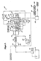
- a system 10 is shown suitable for purifying a water supply containing trichloroethylene in concentrations of from 15 to 40 parts per billion.
- the system 10 has a water influent port 12, typically admitting 20 to 30 gallons per minute, a reactor tank 14 with a series of baffles 16, and a water effluent port 18.
- the water contaminated with trichloroethylene flows into influent port 12 through baffles 16, and out through effluent port 18.
- Baffles 16 do not extend across the entire width of reactor tank 14, rather baffles 16 are disposed in the tank 14 such that the water flows around the sides of baffles 16; this baffle design prevents back-mixing of contaminated with decontaminated water and may also enhance ozone diffusion throughout the water in tank 14.
- the reactor tank 14 is equipped with thirty 40 Watt ultraviolet lamps 20 which provide electromagnetic radiation which includes some wavelengths from 185 nanometers to 254 nanometers.
- the portion of tank 14 near the influent port 12 has two tubular diffuser inlets 22 which admit an ozone/air mixture, produced by an ozone generator 24, into tank 14 and also aid in dispersing this mixture throughout the solution in tank 14.
- the ozone/air mixture in tank 14 acts in conjunction with the known decomposing action of the ultraviolet light produced by the lamps 20 and oxidizes most of the trichloroethylene in solution.
- a compressor 26 provides air to ozone generator 24 and a dryer 28 is positioned between compressor 26 and ozone generator 24 to ensure that the ozone generator's efficiency is not impeded by the presence of water in the air supply.
- Detoxification unit 29 is essentially a column of porous silica gel (quartz chips can also be used with the invention) wherein six 40 watt ultraviolet lamps 31 are positioned to irradiate the column.
- gases carrying volatile organic halogenated compounds such as the trichloroethylene
- detoxification unit 29 decomposes the trichloroethylene not decomposed by the action of the ultraviolet light and the ozone in reactor tank 14; near complete decomposition of the toxic trichloroethylene results.
- Degasser 32 Following treatment by detoxification unit 29, the resulting gases, which include some ozone, are pumped by a compressor 30 to a degasser 32.
- Degasser 32 has substantially detoxified water -- which has had the volatile organic halogenated compounds volatized from it and which has also been treated with ozone and ultraviolet light within reactor tank 14 -- flowing to it from the effluent end of tank 14.
- Degasser 32 employs six ultraviolet lamps 34 to provide ultraviolet light which decomposes residual ozone.
- An air inlet port 36 is also provided on degasser 32 to add make-up air to the system.
- a level gauge 37 is associated with degasser 32 and when degasser 32 becomes filled with detoxified water, a feed back system between level gauge 37 and a centrifugal pump 38 turns on pump 38 and water is pumped from the bottom of degasser 32 back to reactor tank 14. The water pumped back will contain any un-volatized or un-decomposed halogenated compounds; thus, these compounds are returned to the system for further treatment and oxidation.
- Air which has had the ozone removed therefrom by degasser 32, is returned to compressor 26 which mixes make-up air with the recycled air.
- Compressor 26 pumps the gaseous mixture to air dryer 28 which in turn feeds dired air to an ozone generator 24; thus, no gases or volatile organics are vented to the atmosphere.
- the detoxification unit 29 can also decompose other volatile organic halogenated compounds, for example: carbon tetrachloride; tetrachloroethylene; vinyl chloride; ethylene dibromide; methylene chloride, 1,1,1,-trichloroethane; chlorobenzene; hexachloroethane; 1,1-dichloroethane; 1,1,2-trichloroethane, 1,1,2,2-tetrachloroethane; bis(chloromethyl) ether; bis (2-chloroethyl) ether; 2-chloroethyl vinyl ether (mixed); chloroform; 1,2-dichlorobenzene; 1,3-dichlorobenzene; 1,4-dichlorobenzene; 1,1-dichloroethylene; 1,2-trans-dichloro
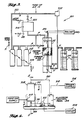
- Waste water contaminated with up to 4,000 parts per million of methylene chloride and also contaminated with phenol, is pumped by a pump 110 from a tank 112 at a rate of 3 to 4 gallons per minute.
- the water passes through a heat exchanger 116 and is then preheated to about 75 to 80°C by a heater 118; thereafter it enters a reactor tank 114.
- Reactor tank 114 is equipped with a set of internal heaters 120 which maintain the reaction temperature of the waste water. Maintaining the reaction temperature enhances oxidation of phenol and also may serve to enhance the rate of methylene chloride vaporization and decomposition.
- Reactor tank 114 is provided with an impermeable wall 122 which divides tank 114 into first and second sections 124 and 126, respectively.
- First section 124 houses internal heaters 120 as well as four baffles 128.
- the baffles 128 are designed to extend only part-way across tank 114 in order to prevent back-mixing of the water. This design may also enhance dispersion of gases which enter tank 114 through a set of tubular diffusers 140.
- Tank 114 is also equipped with an air inlet 130 to provide make-up air to the system.
- Tank 114 can be provided with a levelling gauge 131 to indicate the water level in the tank.
- a compressor 132 pumps air, carrying methylene chloride volatized by the gases entering through tubular diffusers 140, from the top of tank 114 into a detoxification unit 134.
- Detoxification unit 134 is essentially the same as detoxification unit 29.
- Detoxification unit 134 is designed to. decompose the volatized methylene chloride and is essentially a porous bed of silica gel (or quartz chips) irradiated with eight 40 Watt ultraviolet lamps 135 which provide ultraviolet light.
- the ultraviolet light includes some wavelengths from 185 nano-m to 254 nano-m. Due to the similarity between detoxification unit 134 and detoxification unit 29, system 100 can decompose all the same volatile organic halogenated compounds which can be decomposed by system 10.
- paint stripping waste water typically contains traces of the following elements.
- ELEMENT CONCENTRATION (ppm) Chromium 51.0 Zinc 10.0 Copper 0.05 Nickel 0.06 Cadmium 0.02 Lead 0.2
- compressor 132 pumps the gases from the top of unit 134 and through a series of tubular diffusers 140 which bubble the gases into first section 124 of tank 114.
- the gases so treated will be almost completely free of methylene chloride which has been decomposed to, inter alia, formic acid.
- FIG. 2 shows that the gases are pumped by compressor 132 from near the midpoint of first section 124. After the waste-water has passed through the first two of the four baffles 128 and is near the midpoint of first section 124, most of the halogenated compounds have been volatilized from the water; thus, water near wall 122 is essentially detoxified. The gases treated in unit 134 are returned to all portions of first section 124, however, these gases have been detoxified and therefore do not add to the toxicity of the water near wall 122.
- the detoxified water near wall 122 is pumped by a centrifugal pump 142 into second section 126 of tank 114. Also entering second section 126 through a set of tubular diffusers 144 is ozone produced by an ozone generator 146.
- the detoxified water and ozone are mixed in second section 126 of oxidize the intermediate aliphatic acids produced by the oxidation of phenol. Ozone then passes from the top of second section 126 into an ozone decomposer 152 which produces oxygen and releases it to the atmosphere.
- Air entering ozone generator 146 first passes through an air filter 148 and an air dryer 150 which respectively filter and then dry the entering air. Water is pumped into ozone generator 146 in order to cool the generator.
- Second section 126 is generally nearly full of water -- first section 124 is usually about one-half full and has a layer of foam, atop the water -- and water is pumped from near the top of second section 126 through an effluent port 154.
- the effluent water is thus free (or nearly free) of phenol, methylene chloride and formic acid and is safe for environmental release.
- water exiting second section 126 will be at an elevated temperature as it has been heated at several points along its flow route.
- Heat exchanger 116 uses the heat of the effluent water to aid in pre-heating the influent water prior to its entry into tank 114 and energy is thereby conserved.
- water exiting second section 126 can pass through a by-pass 156 which circumvents heat exchanger 116 and channels the effluent water to tank 114 for re-purification.
- Second section 126 can also be equipped with a level gauge 155, and system 100 can be provided, at any of a number of locations, with water flow meters and water temperature indicators (not shown).
- Compressor 132 can be equipped for flow control with a by-pass 158 which allows the gases flowing from detoxification unit 134 to flow around, rather than through, compressor 132.
- System 306 includes a model detoxification unit 308 having a toxic air supply port 310 and an exhaust port 312 and further includes an electrical control panel 314, a power supply 316 and power lines 318, 320, and 321.
- the detoxification unit 308, along with the other portions of system 306, can be used as the detoxification unit portion of either of systems 10 or 100.
- Detoxification unit 308 has a housing 328 with caps 330 and 332, respectively, affixed to the upper and lower ends of housing 328.
- Housing 328 provides a hermetic seal around a 6 to 16 mesh porous silica gel bed 334 (alternatively, a porous bed of quartz chips can be used) and also around a plurality of 40 watt low pressure, high intensity, ultraviolet lamps 336.
- Toxic gases flow through air supply port 310, through the silica gel bed 334, and out through exhaust port 312.
- lamps 336 irradiates silica gel bed 334 and acts to aid in decomposing any volatile organic halogenated compounds in the gases.
- Lamp leads 338 and 340 respectively positioned in mouths 342 and 344, supply power to the lamps 336 from the power lines 321 and 320.
- FIG. 6 a sectional view of detoxification unit 308 taken along the lines 6-6 is shown.
- FIG. 6 shows forty-eight lamps 336; a greater or a lesser number of lamps can be used in other embodiments of the invention.
- Tank 216 and bottles 218 contain aqueous solutions of the volatile organic halogenated compounds and air carrying these compounds was volatilized from either tank 216 or bottles 218.
- test apparatus 210 A variety of embodiments of test apparatus 210 were used. Valves A to H are shown to schematically indicate the different flow paths of the air carrying these compounds when this air passed through the different embodiments of test apparatus 210. Referring to Table 1, in the first, third and fifth group of experiments the air flow was "open", meaning that the air flowed along flow path 219 from the bottom of detoxification unit 212 to the scrubber bottles 214. Bottles 214 trap undecomposed organic halogenated compounds. In these groups of experiments no air flowed from unit 212 to either the tank 216 or to the bottles 218, this can be envisioned by closing valves A and B and opening valve H.
- the air flow was "cyclic", indicating that the air was pumped by compressor 225 along flow path 223 or 221 and was then returned to either of tank 216 or bottles 218. This can be envisioned by opening valves A or B and closing valve H.
- Detoxification unit 212 is essentially a hermetic cylindrical housing with an ultraviolet lamp 220 extending through the center thereof, and with a granular silica gel bed 222 surrounded by heating tape 224.
- Heating tape 224 which heats silica gel bed 222, was activated between runs and nitrogen gas was simultaneously passed through silica gel bed 222. Although this heating/nitrogen treatment temporarily improved the efficacy of the detoxification unit, good results were also obtained without this treatment.
- Valves C and F, and D and E are shown to schematically indicate that there were two further different embodiments of unit 212, one of which allowed air flow through the sides of unit 212 (indicated schematically by opening valves C and E) and one of which allowed air flow through the top and bottom of the unit 212 (indicated schematically by opening valves F and D).
- the embodiment of unit 212 actually used is immaterial to. the experimental results and is therefore not indicated in Table 1.
- Valves I and J, and K and L are shown to indicate that water can be flowing through one of flow paths 229 and 231, or can be batched, as indicated in Table 1.
- the "percent destroyed" column of Table 1 shows that the detoxification unit 212 effectively decomposed all of the organic halogenated compounds which were tested.
- test apparatus 210 In a set of runs initially performed with test apparatus 210, at one point there appeared to be a downward trend in the percentage of halogenated compound decomposition. Another run was performed and thereafter nitrogen gas was passed through the bed to determine if the nitrogen gas could regenerate the bed to full decomposing activity. The rate of decomposition increased back to about 98% indicating that a regeneration effect had in fact occurred.
- the prototype detoxification unit employing silica gel irradiated with ultraviolet light and/or exposed to ozone, can be used in a wide variety of systems in modified forms to destroy a wide variety of volatile organic halogenated compounds. It is believed that any organic halogenated compound which can be decomposed by ultraviolet light and/or ozone and which can be volatized from aqueous solution, can be decomposed by the detoxification unit.
- Such volatile organic halogenated compounds include, but are not limited to: tetrachloroethylene; vinyl chloride; carbon tetrachloride; ethylene dibromide; methylene chloride, 1,1,1,-trichloroethane; chlorobenzene; hexachloroethane; 1,1-dichloroethane; 1,1,2-trichloroethane, 1,1,2,2-tetrachloroethane; chloroethane; bis(chloromethyl ether; bis (2-chloroethyl) ether; 2-chloroethyl vinyl ether (mixed); chloroform; 1,2-dichlorobenzene; 1,3-dichlorobenzene; 1,4-dichlorobenzene; 1,1-dichloroethylene; 1,2-transdichloroethylene; 1,2-dichloropropane; 1,2-dichloropropylene; bis (2-chloroisopropyl) ether; bis (2
- the ultraviolet light used when performing all these experiments contained a plurality of wavelengths, including some wavelengths between 185 nanometers to 254 nanometers.
- a set of unreported experiments was conducted to determine if the wavelengths of the ultraviolet light affected the rate of halogenated compound decomposition.
- ozone was added to a solution of organic halogenated compounds and the solution was irradiated with ultraviolet light.
- An aqueous solution of organic halogenated compounds was introduced into a reactor tank with one centrally located 40 watt ultraviolet lamp. Through the bottom of the tank was fed a mixture of ozone/oxygen, or ozone/air, or ozone/nitrogen.
- the detoxification unit consisted of a glass cylindrical housing containing a column of granular silica gel with glass wool plugs at both ends to retain the silica gel in place, and silicone rubber stoppers at the top and bottom to seal the cylindrical housing. The stoppers were provided with gas inlet and outlet openings.
- the temperature of the silica gel bed was controlled by means of a heating tape 224 as seen in Fig. 3 wrapped around the outside of the cylindrical housing.
- a glass cylinder (2 liter capacity) closed at the top was also used in which 1800 ml of water containing trichloroethylene (TCE) was placed.
- Compressed air from an air pump was passed into the TCE solution in the glass cylinder at selected flow rates, and exited via an outlet tube from the glass cylinder to the bottom of the detoxification unit.
- An ozone inlet for introducing ozone was provided in the outlet tube exiting from the glass cylinder.
- Offgas from the glass cylinder containing the TCE solution was thus passed into the detoxification unit through the silica gel column and out the top of the unit.
- a hexane trap was provided for the gas exiting the detoxification unit to trap any remaining TCE and other volatile compounds.
- This trap consisted of a gas washing bottle (VWR Scientific Inc., Cerritos, CA) charged with 200 ml of hexane. Either all or a portion of the offgas from the detoxification unit was passed through this trap.
- This test apparatus provided a means for testing a batch of TCE-containing solution. Additional volumes of TCE were introduced into the solution in the glass cylinder at selected time intervals to replenish the TCE in solution for additional test runs.
- the cylindrical housing included a 40 watt ultraviolet lamp 220 (74 cm long) extending through the center of the cylinder. For experiments using only ozone exposure, the ultraviolet lamp was omitted.
- the temperature on the tape was controlled by a Variac auto transformer type 3PN1010 (Staco Energy Products Co., Dayton, OH). A thermometer (VWR Scientific Inc.) was installed in the top of the cylinder with the bulb immersed in the silica gel column, and the glass tube was mounted vertically.
- the percent of TCE that passed through the detoxification unit was below one percent.
- the space velocity in this case was 920 reciprocal hours.
- the TCE was maintained at 350 ppb in water but the gas flow rate was increased to 6.3 L/M.
- test Run Nos. 8-16 TCE dosage was reduced from 350 ppb to 50 ppb. All the other parameters were kept constant.
- the volume of TCE that passed through the detoxification unit varied from 3% up to 80%.
- An increase in temperature of 5°C in test Run Nos. 17-20 did not have any significant effect on the removal of TCE in the system.
- Table 5 describes the testing that was done after the partial regeneration of the silica gel. Again, a starting concentration of 50 ppb of TCE was removed from the water solution. The air flow was kept at 6.3 L/M and the ozone input flow was maintained at .3 L/M. The temperature was raised to 50°C and, as shown in Table 5, the amount of TCE passing through the detoxification unit was below detectable limits up to test Run No. 30. After that, there was again a breakthrough of the TCE, and it was concluded that the silica gel was saturated. The silica gel was again partially regenerated with nitrogen at a rate of 1 L/M at 85°C for two hours.
- Table 6 shows the results of tests where the temperature was raised to 60°C. All the other variables were kept at the same levels as in Table 5. In the nineteen tests that were conducted in this series of runs, there was no breakthrough of TCE in the detoxification. It was concluded that a 60°C temperature was required in order to maintain an equilibrium and prevent breakthrough of the TCE through the same silica gel at the operating conditions shown in Table 6.
- TCE (ppb) Gas Flow Thru D-TOX (L/M) 2% O3/O2 Flow (L/M) Temp.
- test Run Nos. 57-60 the TCE in the water was increased to 700 ppb and all other conditions were maintained the same as in Table 6. Twenty two to 26% of the TCE passed through the same silica gel in this case.
- test Run Nos. 61-64 the temperature was raised to 70°C and resulted in a slight increase in the percent of TCE passing through the silica gel.
- test Run Nos. 65-70 the temperature was reduced to 60°C, and the ozone input flow was slightly increased to 0.5 L/M. These two changes again did not seem to have a significant effect on the removal of TCE through the silica gel.
- test Run Nos. 57-60 the TCE in the water was increased to 700 ppb and all other conditions were maintained the same as in Table 6. Twenty two to 26% of the TCE passed through the same silica gel in this case.
- test Run Nos. 61-64 the temperature was raised to 70°C and resulted in a slight increase in the
- Table 8 describes the substitution of 3-9 mesh silica gel for the previously used 6-16 mesh silica gel to determine the effect of mesh size on the adsorption of TCE.
- the weight of the 3-8 mesh silica gel was 147 grams, which was identical to the 6-16 mesh silica gel that was used in the cylinder.
- the coarser silica gel was packed into a 2" NPT stainless steel pipe.
- the apparent volume for the coarser silica gel was 190 cc, whereas the 6-16 mesh was 150 ml. All the tests in Table 8 removed 700 ppb of TCE from the water. Also held constant was the ozone flow rate at .3 L/M and the temperature at 60°C.
- the space velocity through the silica gel was varied from 1042 reciprocal hours to 3253 reciprocal hours. Comparing test Run Nos. 99-103 in Table 8 with test Run Nos. 57-60 in Table 7, the coarser mesh appears to reduce the TCE passing through the silica gel to approximately 1% less than when using the finer mesh silica gel. The same silica gel was used throughout this series of tests.
- Ultraviolet light alone removes 80% or better of the TCE with space velocities in the 2400 reciprocal hour range.
- the addition of ozone with ultraviolet light may enhance the oxidation of the TCE.
- the basic organic halogenated compound detoxification unit (using a bed of either silica gel or quartz chips and irradiation with ultraviolet light and/or exposure to ozone) can also be used in a wide variety of industrial applications other than those previously described. These halogenated compounds are used and/or produced in dry cleaning, in incinerators which produce these compounds as offgases, in many chemical processes, following chemical spills, and in chemical storage tanks; the unit could be used for detoxification in any of these sytems. It is also hypothesized that a smaller-mesh silica gel bed could be used as a purification system for water which contains bacteria. It is known that ultraviolet light kills bacteria and it is believed that passing bacteria contaminated water through the detoxification unit would increase the rate of bacterial destruction.
Abstract
Description
- The invention relates to methods and apparati for decomposing volatile organic compounds contained in contaminated gases and aqueous solutions using silica gel in combination with ultraviolet light and/or ozone.
- Although it is well known that ultraviolet light decomposes volatile organic, halogenated compounds contained in gases (See, U.S. Patent Nos. 4,144,152 and 4,210,503), the rate of decomposition of these compounds has proven unsatisfactory when used in a system in which these compounds are volatilized from a rapidly flowing, aqueous solution and then treated with the ultraviolet light. When ultraviolet light is used for decomposition in such systems, the ultraviolet light does not have sufficient time to effect appreciable decomposition of the continuously flowing halogenated compounds.
- Flowing, aqueous systems containing these toxic, undesirable compounds appear in a variety of situations; for example, well water often contains these compounds and therefore must be purified prior to consumption. Additionally, a wide variety of industrial effluent solutions contain these compounds, one example being the waste water contaminated with halogenated solvents. These compounds are toxic and therefore must be removed. Known detoxification systems typically volatize the halogenated compounds from flowing solution into air; the contaminated air is then released to the atmosphere thereby causing toxic air pollution.
- Thus, what is needed is an apparatus and a method which decomposes these toxic compounds quickly enough to serve as an effective pollution control device. The apparatus and method should also be suitable for use as an air and water purification system.
- The invention provides a method and apparatus for decomposing volatile, organic halogenated compounds contained in gases and aqueous solutions.
- One aspect of the invention is an apparatus for decomposing organic compounds contained in gases and aqueous solutions, comprising:
- a) a reactor tank for simultaneously exposing a contaminated aqueous solution to ozone and ultraviolet radiation to oxidize organic compounds in the solution and to volatilize organic compounds from the solution, said reactor tank having at least one influent port for incoming solution and at least one effluent port for outgoing solution, and said reactor tank having at least one gas diffuser tube proximal to the influent port for introducing ozone into the contaminated solution in the tank, and said reactor tank containing ultraviolet irradiation means;
- b) ozone generator means coupled to at least one gas diffuser tube for generating ozone from air to produce and ozone-air mixture, and for introducing the ozone-air mixture into said reactor tank for reaction with the contaminated solution; and
- c) a detoxification unit coupled to the reactor tank for decomposing volatilized organic halogenated compounds contained in gases, said detoxification unit having a plurality of irradiating means for irradiating the volatilized organic compounds, and having a porous adsorbent bed for adsorbing ozone and organic compounds arranged such that said porous adsorbent bed is surrounding said irradiating means and at a distance effective to promote reduction of said volatile organic halogenated compounds in said gases.
- The irradiating means may be ultraviolet lamps and may be enclosed in quartz sheaths.
- The porous adsorbent bed is preferably silica gel, and may include means for heating the adsorbent bed.
- Another aspect of the invention is an apparatus for decomposing volatile organic compounds contained in gases comprising:
- a) a housing having a gas supply port, a gas exhaust port, and a gas flow path between said gas supply port and said gas exhaust port;
- b) a porous adsorbent bed located in said gas flow path, wherein said porous adsorbent bed is capable of adsorbing ozone and volatile organic halogenated compounds from the gaseous state; and
- c) means for irradiating said porous adsorbent bed with ultraviolet light, said porous adsorbent bed surrounding said irradiating means and at a distance effective to promote reduction of said volatile organic compounds in gases.
- Yet another aspect of the invention is an apparatus for decomposing volatile organic halogenated compounds contained in gases comprising:
- a) a housing having a gas supply port, a gas exhaust port, and a gas flow path between said gas supply port and said gas exhaust port;
- b) a porous adsorbent bed located in said gas flow path, wherein said porous adsorbent bed is capable of adsorbing ozone and volatile organic halogenated compounds from the gaseous state; and
- c) means for exposing said porous adsorbent bed to ozone to promote reduction of said volatile organic compounds in said gases.
- Another aspect of the invention is a method for decomposing volatile organic halogenated compounds contained in gases comprising passing gas carrying the volatile organic compounds through a porous adsorbent bed of silica gel while irradiating the porous bed with ultraviolet light and/or exposing the porous adsorbent bed to ozone for an amount of time effective to appreciably decompose the volatile organic halogenated compounds in said gases.
- Yet another aspect of the invention is a method for decomposing volatile, toxic compounds contained in aqueous solutions comprising:
- a) volatilizing the volatile, toxic compounds from a contaminated aqueous solution to a gaseous carrier by passing said gaseous carrier through said aqueous solutions; and
- b) passing said gaseous carrier through a porous adsorbent bed of silica gel while exposing said porous adsorbent bed to ultraviolet light and/or ozone to appreciably decompose the volatile organic halogenated compounds in said gases.
- This aspect of the invention may have the aqueous solution continuously flowing and may further comprise recycling the gaseous carrier to further remove toxic compounds by returning the gaseous carrier to the continuously flowing aqueous solution to volatilize the volatile, toxic compounds and passing said returned gaseous carrier through the porous adsorbent bed while exposing said porous adsorbent bed to ultraviolet light and/or ozone.
- It is thus an object of the invention to provide a sufficient rate of decomposition of volatile organic halogenated compounds so that such compounds volatilized from a flowing solution, or contained in flowing gaseous systems can be completely or substantially decomposed.
- Other features and advantages of the present invention will become apparent from the following, more detailed description which illustrates, by way of example, the principles of the invention.
-
- FIG. 1 shows a system for removing volatile organic halogenated compounds from potable water.
- FIG. 2 shows a system for removing phenol and volatile organic halogenated compounds from waste-water produced following paint stripping.
- FIG. 3 shows an apparatus which was used to test the efficacy of the invention.
- FIG. 4 shows a detoxification unit for use in the systems of FIGS. 1 and 2.
- FIG. 5 is a sectional view of the detoxification unit of FIG. 4 taken along the lines 5-5.
- FIG. 6 is a sectional view of the detoxification unit of FIG. 4 taken along the lines 6-6.
- Referring to FIG. 1, a
system 10 is shown suitable for purifying a water supply containing trichloroethylene in concentrations of from 15 to 40 parts per billion. Thesystem 10 has a waterinfluent port 12, typically admitting 20 to 30 gallons per minute, areactor tank 14 with a series ofbaffles 16, and awater effluent port 18. The water contaminated with trichloroethylene flows intoinfluent port 12 throughbaffles 16, and out througheffluent port 18.Baffles 16 do not extend across the entire width ofreactor tank 14, ratherbaffles 16 are disposed in thetank 14 such that the water flows around the sides ofbaffles 16; this baffle design prevents back-mixing of contaminated with decontaminated water and may also enhance ozone diffusion throughout the water intank 14. - The
reactor tank 14 is equipped with thirty 40 Wattultraviolet lamps 20 which provide electromagnetic radiation which includes some wavelengths from 185 nanometers to 254 nanometers. The portion oftank 14 near theinfluent port 12 has twotubular diffuser inlets 22 which admit an ozone/air mixture, produced by anozone generator 24, intotank 14 and also aid in dispersing this mixture throughout the solution intank 14. The ozone/air mixture intank 14 acts in conjunction with the known decomposing action of the ultraviolet light produced by thelamps 20 and oxidizes most of the trichloroethylene in solution. - A
compressor 26 provides air toozone generator 24 and adryer 28 is positioned betweencompressor 26 andozone generator 24 to ensure that the ozone generator's efficiency is not impeded by the presence of water in the air supply. - Following treatment of the water with ozone and ultraviolet light, the trichloroethylene and other volatile compounds volatized by the ozone/air mixture are pumped to a
detoxification unit 29 by means of acompressor 30.Detoxification unit 29 is essentially a column of porous silica gel (quartz chips can also be used with the invention) wherein six 40 watt ultraviolet lamps 31 are positioned to irradiate the column. As will be discussed further later, it has been discovered that passing gases carrying volatile organic halogenated compounds (such as the trichloroethylene) through a bed of silica gel or quartz chips and irradiating the bed with ultraviolet light, substantially enhances the rate of decomposition of these compounds. Thus,detoxification unit 29 decomposes the trichloroethylene not decomposed by the action of the ultraviolet light and the ozone inreactor tank 14; near complete decomposition of the toxic trichloroethylene results. - Following treatment by
detoxification unit 29, the resulting gases, which include some ozone, are pumped by acompressor 30 to adegasser 32. Degasser 32 has substantially detoxified water -- which has had the volatile organic halogenated compounds volatized from it and which has also been treated with ozone and ultraviolet light withinreactor tank 14 -- flowing to it from the effluent end oftank 14. Degasser 32 employs sixultraviolet lamps 34 to provide ultraviolet light which decomposes residual ozone. Anair inlet port 36 is also provided ondegasser 32 to add make-up air to the system. - A
level gauge 37 is associated withdegasser 32 and whendegasser 32 becomes filled with detoxified water, a feed back system betweenlevel gauge 37 and acentrifugal pump 38 turns onpump 38 and water is pumped from the bottom ofdegasser 32 back toreactor tank 14. The water pumped back will contain any un-volatized or un-decomposed halogenated compounds; thus, these compounds are returned to the system for further treatment and oxidation. - Air, which has had the ozone removed therefrom by
degasser 32, is returned tocompressor 26 which mixes make-up air with the recycled air.Compressor 26 pumps the gaseous mixture toair dryer 28 which in turn feeds dired air to anozone generator 24; thus, no gases or volatile organics are vented to the atmosphere. - It can be seen that a cost-efficient system which decomposes nearly all the toxic trichloroethylene in drinking water is provided. Because the
detoxification unit 29 can also decompose other volatile organic halogenated compounds, for example: carbon tetrachloride; tetrachloroethylene; vinyl chloride; ethylene dibromide; methylene chloride, 1,1,1,-trichloroethane; chlorobenzene; hexachloroethane; 1,1-dichloroethane; 1,1,2-trichloroethane, 1,1,2,2-tetrachloroethane; bis(chloromethyl) ether; bis (2-chloroethyl) ether; 2-chloroethyl vinyl ether (mixed); chloroform; 1,2-dichlorobenzene; 1,3-dichlorobenzene; 1,4-dichlorobenzene; 1,1-dichloroethylene; 1,2-trans-dichloroethylene; 1,2-dichloropropane; 1,2-dichloropropylene; bis (2-chloroisopropyl) ether; bis (2-chloroethoxy) methane; methyl chloride; methyl bromide; bromoform; dichloro dichlorobromomethane; trichlorobromomethane; trichlorofluoromethane; dichloro fluoromethane; chlorodibromomethane; this same system can be used to detoxify water contaminated with any of these compounds. - Referring to FIG. 2, a
system 100 is shown suitable for removing methylene chloride and phenol from waste water -- both compounds are typical by-products of paint stripping. Waste water, contaminated with up to 4,000 parts per million of methylene chloride and also contaminated with phenol, is pumped by apump 110 from a tank 112 at a rate of 3 to 4 gallons per minute. The water passes through aheat exchanger 116 and is then preheated to about 75 to 80°C by aheater 118; thereafter it enters areactor tank 114.Reactor tank 114 is equipped with a set ofinternal heaters 120 which maintain the reaction temperature of the waste water. Maintaining the reaction temperature enhances oxidation of phenol and also may serve to enhance the rate of methylene chloride vaporization and decomposition. -
Reactor tank 114 is provided with animpermeable wall 122 which dividestank 114 into first andsecond sections First section 124 housesinternal heaters 120 as well as four baffles 128. Thebaffles 128 are designed to extend only part-way acrosstank 114 in order to prevent back-mixing of the water. This design may also enhance dispersion of gases which entertank 114 through a set oftubular diffusers 140.Tank 114 is also equipped with anair inlet 130 to provide make-up air to the system.Tank 114 can be provided with a levellinggauge 131 to indicate the water level in the tank. - A
compressor 132 pumps air, carrying methylene chloride volatized by the gases entering throughtubular diffusers 140, from the top oftank 114 into adetoxification unit 134.Detoxification unit 134 is essentially the same asdetoxification unit 29.Detoxification unit 134 is designed to. decompose the volatized methylene chloride and is essentially a porous bed of silica gel (or quartz chips) irradiated with eight 40 Wattultraviolet lamps 135 which provide ultraviolet light. The ultraviolet light includes some wavelengths from 185 nano-m to 254 nano-m. Due to the similarity betweendetoxification unit 134 anddetoxification unit 29,system 100 can decompose all the same volatile organic halogenated compounds which can be decomposed bysystem 10. - It can be seen in FIG. 2 that prior to entry of the waste water into
tank 114, a solution of H₂O₂ and FeSO4 (pumped from atank 136 by a diaphram pump 138) is added to the waste water. This solution serves to oxidize the phenol and, as discussed previously, works best when the waste water is heated. - It should be noted that paint stripping waste water typically contains traces of the following elements.
ELEMENT CONCENTRATION (ppm) Chromium 51.0 Zinc 10.0 Copper 0.05 Nickel 0.06 Cadmium 0.02 Lead 0.2 - The addition of the FeSO₄, which acts as an oxidation catalyst for phenol, may be unnecessary as one or more of these elements which already are in the waste--water could act as the phenol oxidation catalyst.
- Following treatment in
detoxification unit 134,compressor 132 pumps the gases from the top ofunit 134 and through a series oftubular diffusers 140 which bubble the gases intofirst section 124 oftank 114. The gases so treated will be almost completely free of methylene chloride which has been decomposed to, inter alia, formic acid. FIG. 2 shows that the gases are pumped bycompressor 132 from near the midpoint offirst section 124. After the waste-water has passed through the first two of the fourbaffles 128 and is near the midpoint offirst section 124, most of the halogenated compounds have been volatilized from the water; thus, water nearwall 122 is essentially detoxified. The gases treated inunit 134 are returned to all portions offirst section 124, however, these gases have been detoxified and therefore do not add to the toxicity of the water nearwall 122. - The detoxified water near
wall 122 is pumped by acentrifugal pump 142 intosecond section 126 oftank 114. Also enteringsecond section 126 through a set of tubular diffusers 144 is ozone produced by anozone generator 146. The detoxified water and ozone are mixed insecond section 126 of oxidize the intermediate aliphatic acids produced by the oxidation of phenol. Ozone then passes from the top ofsecond section 126 into anozone decomposer 152 which produces oxygen and releases it to the atmosphere. - Air entering
ozone generator 146 first passes through anair filter 148 and anair dryer 150 which respectively filter and then dry the entering air. Water is pumped intoozone generator 146 in order to cool the generator. -
Second section 126 is generally nearly full of water --first section 124 is usually about one-half full and has a layer of foam, atop the water -- and water is pumped from near the top ofsecond section 126 through aneffluent port 154. The effluent water is thus free (or nearly free) of phenol, methylene chloride and formic acid and is safe for environmental release. - It can be seen that the water exiting
second section 126 will be at an elevated temperature as it has been heated at several points along its flow route.Heat exchanger 116 uses the heat of the effluent water to aid in pre-heating the influent water prior to its entry intotank 114 and energy is thereby conserved. Alternatively, water exitingsecond section 126 can pass through a by-pass 156 which circumventsheat exchanger 116 and channels the effluent water totank 114 for re-purification. -
Second section 126 can also be equipped with a level gauge 155, andsystem 100 can be provided, at any of a number of locations, with water flow meters and water temperature indicators (not shown).Compressor 132 can be equipped for flow control with a by-pass 158 which allows the gases flowing fromdetoxification unit 134 to flow around, rather than through,compressor 132. - It would also be possible to use
system 100 for detoxification of waste water which contains volatile organic halogenated compounds but contains no phenol. For treatment of phenol-free waste water one would simply not add the H₂O₂ and the FeSO₄ to the waste water. - Referring to FIG. 4, a
system 306 is shown.System 306 includes amodel detoxification unit 308 having a toxicair supply port 310 and anexhaust port 312 and further includes anelectrical control panel 314, a power supply 316 andpower lines Detoxification unit 308,electrical control panel 314 and acompressor 322, which pumps the toxic air or gases intodetoxification unit 308, all rest on abase 326. - The
detoxification unit 308, along with the other portions ofsystem 306, can be used as the detoxification unit portion of either ofsystems - Referring to FIG. 5, a sectional view of
detoxification unit 308 taken along the lines 5-5, is shown.Detoxification unit 308 has a housing 328 withcaps 330 and 332, respectively, affixed to the upper and lower ends of housing 328. Housing 328 provides a hermetic seal around a 6 to 16 mesh porous silica gel bed 334 (alternatively, a porous bed of quartz chips can be used) and also around a plurality of 40 watt low pressure, high intensity,ultraviolet lamps 336. Toxic gases flow throughair supply port 310, through thesilica gel bed 334, and out throughexhaust port 312. The ultraviolet light provided bylamps 336 irradiatessilica gel bed 334 and acts to aid in decomposing any volatile organic halogenated compounds in the gases. Lamp leads 338 and 340 respectively positioned inmouths lamps 336 from thepower lines - Referring to FIG. 6, a sectional view of
detoxification unit 308 taken along the lines 6-6 is shown. FIG. 6 shows forty-eightlamps 336; a greater or a lesser number of lamps can be used in other embodiments of the invention. - Prior to developing
systems - In a set of experiments, the results of which are summarized at Table A, the efficacy of decomposing volatile organic halogenated compounds carried by gases, wherein the gases are passed through a bed of silica gel which is irradiated with ultraviolet light, was conclusively demonstrated.
- In the experiments summarized at Table A, a 1 inch diameter embodiment of a detoxification unit, similar in all other respects to 2 inch embodiment of a
detoxification unit 212 seen in FIG. 3, was used. A cylinder of compressed air and vinyl chloride, containing 53 ppm vinyl chloride, released the compressed mixture at 4 liters/minute for 15 minutes into the detoxification unit. The products were thereafter passed through a charcoal bed. Charcoal is known to absorb vinyl chloride; therefore undecomposed vinyl chloride was trapped in the bed. Gas chromatography was performed on the charcoal to determine the amount of undecomposed vinyl chloride and from this determination the percentage of decomposition can be readily seen.TABLE A RUN NO. CONDITIONS PERCENTAGE OF VINYL CHLORIDE FOUND IN TRAP 1 Detoxification unit by-passed by the compressed mixture. 100% 2 Mixture passes through the detoxification unit. 0.03% 3 Mixture passes through the detoxification unit but the UV light is off. 36% 4 Mixture passes through detoxification unit but the silica gel bed has been removed from detoxification unit, U.V. light is on. 5.8% - Thus, comparing the amount trapped shown in Run No. 4 (without silica gel), to the amount trapped in Run No. 2 (using ultraviolet light irradiation of the silica gel bed), one can see that a considerably greater percentage of the vinyl chloride is destroyed when using ultraviolet light irradiation of the silica gel bed.
- Another series of experiments were performed all of which involved passing air carrying organic halogenated compounds through a silica gel bed which is irradiated with ultraviolet light; the results are summarized on Table 1.


- Referring to FIG. 3, a basic catalytic
decomposition test apparatus 210 which was essentially the apparatus used to perform the experiments summarized at Table 1, is shown.Tank 216 andbottles 218 contain aqueous solutions of the volatile organic halogenated compounds and air carrying these compounds was volatilized from eithertank 216 orbottles 218. - A variety of embodiments of
test apparatus 210 were used. Valves A to H are shown to schematically indicate the different flow paths of the air carrying these compounds when this air passed through the different embodiments oftest apparatus 210. Referring to Table 1, in the first, third and fifth group of experiments the air flow was "open", meaning that the air flowed alongflow path 219 from the bottom ofdetoxification unit 212 to thescrubber bottles 214.Bottles 214 trap undecomposed organic halogenated compounds. In these groups of experiments no air flowed fromunit 212 to either thetank 216 or to thebottles 218, this can be envisioned by closing valves A and B and opening valve H. - In the second and fourth group of experiments, the air flow was "cyclic", indicating that the air was pumped by
compressor 225 alongflow path tank 216 orbottles 218. This can be envisioned by opening valves A or B and closing valve H. -
Detoxification unit 212 is essentially a hermetic cylindrical housing with anultraviolet lamp 220 extending through the center thereof, and with a granularsilica gel bed 222 surrounded byheating tape 224.Heating tape 224, which heatssilica gel bed 222, was activated between runs and nitrogen gas was simultaneously passed throughsilica gel bed 222. Although this heating/nitrogen treatment temporarily improved the efficacy of the detoxification unit, good results were also obtained without this treatment. - In the various runs of the experiments summarized in Table 1, air flowing from one of
tank 216 orbottles 218 flows to the top ofdetoxification unit 212, throughsilica gel bed 222, and out through the bottom ofdetoxification unit 212. Several different embodiments ofdetoxification unit 212 were used with these experiments.Unit 212 shown in FIG. 3 has a 2 inch housing diameter; other embodiments of the detoxification unit had various housing diameters as indicated at Table 1. A make-up air inlet 230 is shown which can be used to add lost air to the system. - One can envision the
bottles 218 not being used by closing valve G, indicating there is no gas flow along path 227 and thantank 216 supplied the gases to the system through open path 233. It is immaterial to the results which oftank 216 andbottles 218 were used with the various experimental runs as both are equivalent in function; therefore there is no indication in Table 1 which actually was used. - Valves C and F, and D and E, are shown to schematically indicate that there were two further different embodiments of
unit 212, one of which allowed air flow through the sides of unit 212 (indicated schematically by opening valves C and E) and one of which allowed air flow through the top and bottom of the unit 212 (indicated schematically by opening valves F and D). The embodiment ofunit 212 actually used is immaterial to. the experimental results and is therefore not indicated in Table 1. - Valves I and J, and K and L, are shown to indicate that water can be flowing through one of
flow paths - In the case of vinyl chloride (CH₂=CHCl), this compound was not volatized from a solution in
tank 216 orbottles 218 but rather was released from a compressed cylinder containing a mixture of air and vinyl chloride. The mixture was passed through thedetoxification unit 212 and then to a charcoal column trap (not shown) rather than tobottles 214. - The "percent destroyed" column of Table 1 shows that the
detoxification unit 212 effectively decomposed all of the organic halogenated compounds which were tested. In a set of runs initially performed withtest apparatus 210, at one point there appeared to be a downward trend in the percentage of halogenated compound decomposition. Another run was performed and thereafter nitrogen gas was passed through the bed to determine if the nitrogen gas could regenerate the bed to full decomposing activity. The rate of decomposition increased back to about 98% indicating that a regeneration effect had in fact occurred. - Based on the result of the experiments summarized in Table 1 and Table A, it is hypothesized that the silica gel bed performs two functions which aid in halogenated compound decomposition:
- (1) The bed absorbs and concentrates the compounds on a large surface area to allow decomposition by ultraviolet light of the accessible, concentrated compounds;
- (2) The bed also seems to have a catalytic effect which enhances the decomposition by ultraviolet light.
- Thus the prototype detoxification unit, employing silica gel irradiated with ultraviolet light and/or exposed to ozone, can be used in a wide variety of systems in modified forms to destroy a wide variety of volatile organic halogenated compounds. It is believed that any organic halogenated compound which can be decomposed by ultraviolet light and/or ozone and which can be volatized from aqueous solution, can be decomposed by the detoxification unit. Such volatile organic halogenated compounds include, but are not limited to: tetrachloroethylene; vinyl chloride; carbon tetrachloride; ethylene dibromide; methylene chloride, 1,1,1,-trichloroethane; chlorobenzene; hexachloroethane; 1,1-dichloroethane; 1,1,2-trichloroethane, 1,1,2,2-tetrachloroethane; chloroethane; bis(chloromethyl ether; bis (2-chloroethyl) ether; 2-chloroethyl vinyl ether (mixed); chloroform; 1,2-dichlorobenzene; 1,3-dichlorobenzene; 1,4-dichlorobenzene; 1,1-dichloroethylene; 1,2-transdichloroethylene; 1,2-dichloropropane; 1,2-dichloropropylene; bis (2-chloroisopropyl) ether; bis (2-chloroethoxy) methane; methyl chloride; methyl bromide; bromoform; dichlorobromomethane; trichlorobromomethane; trichlorofluoromethane; dichlorofluoromethane; chlorodibromomethane; and 1,2,dibromo-3,chloropropane.
- Once it was determined that the silica gel bed in combination with ultraviolet light did increase rate of trichloroethylene destruction, a slightly modified apparatus, similar in function to a conventional counter-current air stripping tower, was fabricated. The modified apparatus (not shown) passed water downwardly through a column of aluminum chips and passed air upwardly through the column. The air then flowed to a one-inch diameter detoxification unit which had either a bed of silica gel or porous quartz chips irradiated by ultraviolet light, and was in all other respects the same as the two-inch
diameter detoxification unit 212 seen in FIG. 3. - Using this apparatus, it was demonstrated that the bed of quartz chips also enhanced the rate of trichloroethylene decomposition, however, the rate did not increase to as high a level as that observed when a silica gel bed was used.
- The results of these experiments in which the halogenated compounds were stripped from water in an aluminum chip column by counter-current air flow, in combination with the results of the experiments summarized in Table 1 and Table A, shows that the detoxification unit of this invention could accept and purify contaminated air from a conventional counter-current water/air stripping tower. Contaminated air flowing from water/air stripping tower is generally simply released to the atmosphere.
- Other experiments also demonstrated that the detoxification unit of this invention could decompose volatile organic halogenated compounds carried by any of dry, humid or water saturated air.
- The ultraviolet light used when performing all these experiments contained a plurality of wavelengths, including some wavelengths between 185 nanometers to 254 nanometers. A set of unreported experiments was conducted to determine if the wavelengths of the ultraviolet light affected the rate of halogenated compound decomposition. In these experiments, described in greater detail below, ozone was added to a solution of organic halogenated compounds and the solution was irradiated with ultraviolet light.
- An aqueous solution of organic halogenated compounds was introduced into a reactor tank with one centrally located 40 watt ultraviolet lamp. Through the bottom of the tank was fed a mixture of ozone/oxygen, or ozone/air, or ozone/nitrogen.
- Two different 40 watt ultraviolet lamps were used with these experiments, both of these lamps emitted the major part of their energy at 254 nanometers. One of these two lamps also emitted some of its energy at 185 nanometers energy, but less than 1% of the total. The lamp with the 185 nanometers component increased the oxidation rate of 1,2,dibromo-3,chloropropane, various PCBs, Lindane and hexachlorobenzene, three-fold as compared with the oxidation rate achieved with the lamp which did not have the 185 nanometers component. Thus the oxidation rate of these halogenated compounds is increased by increasing the proportion of energy at 185 nanometers. These results can reasonably be extrapolated and it can be seen that the decomposition rate of other halogenated compounds would also likely be increased by lamps which emit more than 1% of their energy at 185 nanometers. However, when using lamps which either emitted some energy at 185 nanometers, or did not emit any, for the ultraviolet-ozonation of pentachlorophenol, the oxidation rate was only about 10% greater than the oxidation rate achieved when using ozone in the absence of ultraviolet light.
- In a set of experiments summarized at Table 2, it was demonstrated that the oxidation rate of certain organic compounds in aqueous solution, when H₂O₂ is added to the solution and it is thereafter irradiated with ultraviolet light, was enhanced by elevating the temperature of solution to 80°C.
TABLE 2 OXIDATION OF ORGANICS WITH UV/H₂O₂ at 80°C Compounds Oxidized Time** (min) Temp (°C) Number of Runs Total of Organic Carbon*** (ppm) Fatty acids 0 80 6 33,300 480 80 12,700 780 80 7,200 Fatty acids 0 RT 1 33,300 480 RT 23,400 Naphthenic acids 0 RT 1 430 120 RT 215 Naphthenic acids 0 80 2 430 120 80 42 * RT indicates the reaction was carried out at room temperatures. ** Time indicates the time of treatment with ultraviolet light (in minutes) ***Compound concentrations are listed in "Total of Organic Carbon" at start of treatment (time = 0), and following treatment for the times specified. - Comparing the tests done at room temperature with those done at 80°C it can be seen that elevating the reaction temperature increased the oxidation rate of all the compounds listed on Table 2. In a set of unreported experiments it was shown that elevating the reaction temperature to 80°C also increased the oxidation rate (in a system using ultraviolet light and H₂O₂ for oxidation) of solutions of the following compounds:
- c) formaldehyde and formic acid;
- d) citric acid and oxalic acid;
- e) phenol and methylene chloride;
- f) phenol and isopropyl alcohol.
- In another set of experiments it was shown that the rate of oxidation of certain compounds in aqueous solution, when using irradiation of the solution with ultraviolet light and addition of ozone to the solution, was enhanced by elevating the solution temperature to 80°C. The results are summarized at Table 3.
TABLE 3 OXIDATION OF ORGANICS WITH UV/03 at 80°C Compounds Oxidized (major constituents) Time** (min) Temp. (°C) TOC*** (ppm) Number of runs Phenol + methylene chloride 0 RT* 5310 1 150 RT 5680 260 RT 4520 Phenol + methylene chloride 0 80 5310 1 150 80 5167 260 80 2372 Naphthenic acids 0 RT 141 1 60 RT 76 90 RT 10 Naphthenic acids 0 80 141 2 60 80 34 90 80 N.D.**** Naphthenic acids 0 80 340 3 120 80 60 * RT indicates the reaction was carried out at room temperature. ** Time, indicates time of treatment with ultraviolet light (in minutes) *** TOC means total of organic carbon concentration at start of treatment (time=0), and following treatment for the times specified. ****N.D. means none was detectable. - Comparing the tests done at room temperature with those done at 80°C, it can be seen that elevating the temperature increases the oxidation rate. In a set of unreported experiments it was shown that the oxidation rate of both Butachlor and EDTA (when using ultraviolet light and ozone for oxidation) was also increased by elevating the temperature to 80°C.
- It was also observed that when using this system, the oxidation rate of long chain alcohols was not increased by elevating the temperature.
- Additional experiments were performed with a prototype detoxification unit to demonstrate the unit's efficacy in decomposing volatile organic halogenated compounds with ultraviolet light and/or ozone exposure. In this series of experiments, a 1.3 inch diameter embodiment of a detoxification unit similar to
detoxification unit 212 as seen in Fig. 3 was used with the following modifications. The detoxification unit consisted of a glass cylindrical housing containing a column of granular silica gel with glass wool plugs at both ends to retain the silica gel in place, and silicone rubber stoppers at the top and bottom to seal the cylindrical housing. The stoppers were provided with gas inlet and outlet openings. The temperature of the silica gel bed was controlled by means of aheating tape 224 as seen in Fig. 3 wrapped around the outside of the cylindrical housing. A glass cylinder (2 liter capacity) closed at the top was also used in which 1800 ml of water containing trichloroethylene (TCE) was placed. Compressed air from an air pump was passed into the TCE solution in the glass cylinder at selected flow rates, and exited via an outlet tube from the glass cylinder to the bottom of the detoxification unit. An ozone inlet for introducing ozone was provided in the outlet tube exiting from the glass cylinder. Offgas from the glass cylinder containing the TCE solution was thus passed into the detoxification unit through the silica gel column and out the top of the unit. A hexane trap was provided for the gas exiting the detoxification unit to trap any remaining TCE and other volatile compounds. This trap consisted of a gas washing bottle (VWR Scientific Inc., Cerritos, CA) charged with 200 ml of hexane. Either all or a portion of the offgas from the detoxification unit was passed through this trap. - This test apparatus provided a means for testing a batch of TCE-containing solution. Additional volumes of TCE were introduced into the solution in the glass cylinder at selected time intervals to replenish the TCE in solution for additional test runs. For experiments using ultraviolet irradiation the cylindrical housing included a 40 watt ultraviolet lamp 220 (74 cm long) extending through the center of the cylinder. For experiments using only ozone exposure, the ultraviolet lamp was omitted. The temperature on the tape was controlled by a Variac auto transformer type 3PN1010 (Staco Energy Products Co., Dayton, OH). A thermometer (VWR Scientific Inc.) was installed in the top of the cylinder with the bulb immersed in the silica gel column, and the glass tube was mounted vertically.
- In the first set of experiments, the results of which are summarized in Table 4, the efficacy of the removal of volatile organic halogenated compounds in a solution, using compressed air and using TCE as a model compound, wherein air was passed through a silica gel and exposed only to ozone, i.e. not irradiated with ultraviolet light, was conclusively demonstrated.
- In the experiments summarized at Table 4, water containing various concentrations (ppm) of TCE, was stripped with air and the air containing the removed TCE was allowed to flow into the detoxification unit and through the same silica gel at a rate of 1 liter/minute (L/M) for 8 minutes. Compressed air was supplied by an air pump at various air flow rates. Ozone input flow and temperature were held constant. Test Run Nos. 1 through 7 employed a concentration of 350 ppb of TCE, an ozone flow in oxygen of 0.3 liters per minute and a silica gel temperature of 40°C. In test Run Nos. 1 through 4, the compressed air flow was 2.3 L/M.
- As shown in Table 4, the percent of TCE that passed through the detoxification unit was below one percent. The space velocity in this case was 920 reciprocal hours. In test Run Nos. 5-7, the TCE was maintained at 350 ppb in water but the gas flow rate was increased to 6.3 L/M. As shown, there was a large increase in the amount of TCE that passed through the detoxification unit, starting at 8.9% (2520 reciprocal hours). In Table 4, test Run Nos. 8-16, TCE dosage was reduced from 350 ppb to 50 ppb. All the other parameters were kept constant.
- The volume of TCE that passed through the detoxification unit varied from 3% up to 80%. An increase in temperature of 5°C in test Run Nos. 17-20 did not have any significant effect on the removal of TCE in the system.
- Because it appeared that saturation of the same silica gel was occurring and limiting removal of the TCE, the silica gel was first partially regenerated by passing nitrogen through the gel at about 1 L/M at 85°C for two hours, then the testing continued using the detoxification unit described above.
TABLE 4 REMOVAL OF TCE FROM WATER FOLLOWED BY OXIDATION OF THE REMOVED TCE WITH O₃ IN A SiO₂ COLUMN IN THE ABSENCE OF UV LIGHT Test Run No. TCE (ppb) Gas Flow Thru D-TOX (L/M) 2% O₃/O₂ Flow (L/M) Temp. (°C) % of TCE Remaining Velocity (hr⁻¹) 1 350 2.3 0.3 ± 0.05 40 0.45 920 2 350 2.3 0.3 ± 0.05 40 0.39 920 3 350 2.3 0.3 ± 0.05 40 0.24 920 4 350 2.3 0.3 ± 0.05 40 0.35 920 5 350 6.3 0.3 ± 0.05 40 8.9 2520 6 350 6.3 0.3 ± 0.05 40 18 2520 7 350 6.3 0.3 ± 0.05 40 25 2520 8 50 6.3 0.3 ± 0.05 40 80 2520 9 50 6.3 0.3 ± 0.05 40 33 2520 10 50 6.3 0.3 ± 0.05 40 20 2520 11 50 6.3 0.3 ± 0.05 40 3.0 2520 12 50 6.3 0.3 ± 0.05 40 11 2520 13 50 6.3 0.3 ± 0.05 40 36 2520 14 50 6.3 0.3 ± 0.05 40 20 2520 15 50 6.3 0.3 ± 0.05 40 47 2520 16 50 6.3 0.3 ± 0.05 40 47 2520 17 50 6.3 0.3 ± 0.05 45 44 2520 18 50 6.3 0.3 ± 0.05 45 36 2520 19 50 6.3 0.3 ± 0.05 45 28 2520 20 50 6.3 0.3 ± 0.05 45 50 2520 - Table 5 describes the testing that was done after the partial regeneration of the silica gel. Again, a starting concentration of 50 ppb of TCE was removed from the water solution. The air flow was kept at 6.3 L/M and the ozone input flow was maintained at .3 L/M. The temperature was raised to 50°C and, as shown in Table 5, the amount of TCE passing through the detoxification unit was below detectable limits up to test Run No. 30. After that, there was again a breakthrough of the TCE, and it was concluded that the silica gel was saturated. The silica gel was again partially regenerated with nitrogen at a rate of 1 L/M at 85°C for two hours.
TABLE 5 REMOVAL OF TCE FROM WATER FOLLOWED BY OXIDATION OF THE REMOVED OFF TCE WITH O₃ IN A SiO₂ COLUMN IN THE ABSENCE OF UV LIGHT Test Run No. TCE (ppb) Gas Flow Thru D-TOX (L/M) 2% O₃/O₂ Flow (L/M) Temp. (°C) % of TCE Remaining Velocity (hr⁻¹) 21 50 6.3 0.3 ± 0.05 50 0 2520 22 50 6.3 0.3 ± 0.05 50 0 2520 23 50 6.3 0.3 ± 0.05 50 0 2520 24 50 6.3 0.3 ± 0.05 50 0 2520 25 50 6.3 0.3 ± 0.05 50 0 2520 26 50 6.3 0.3 ± 0.05 50 0 2520 27 50 6.3 0.3 ± 0.05 50 0 2520 28 50 6.3 0.3 ± 0.05 50 0 2520 29 50 6.3 0.3 ± 0.05 50 0 2520 30 50 6.3 0.3 ± 0.05 50 0 2520 31 50 6.3 0.3 ± 0.05 50 16 2520 32 50 6.3 0.3 ± 0.05 50 21 2520 33 50 6.3 0.3 ± 0.05 50 29 2520 34 50 6.3 0.3 ± 0.05 50 34 2520 35 50 6.3 0.3 ± 0.05 50 38 2520 36 50 6.3 0.3 ± 0.05 50 48 2520 37 50 6.3 0.3 ± 0.05 50 48 2520 - Table 6 shows the results of tests where the temperature was raised to 60°C. All the other variables were kept at the same levels as in Table 5. In the nineteen tests that were conducted in this series of runs, there was no breakthrough of TCE in the detoxification. It was concluded that a 60°C temperature was required in order to maintain an equilibrium and prevent breakthrough of the TCE through the same silica gel at the operating conditions shown in Table 6.
TABLE 6 REMOVAL OF TCE FROM WATER FOLLOWED BY OXIDATION OF THE REMOVED TCE WITH O₃ IN A SiO₂ COLUMN IN THE ABSENCE OF UV LIGHT Test Run No. TCE (ppb) Gas Flow Thru D-TOX (L/M) 2% O₃/O₂ Flow (L/M) Temp. (°C) % of TCE Remaining Velocity (hr⁻¹) 38 50 6.3 0.3 ± 0.05 60 0 2520 39 50 6.3 0.3 ± 0.05 60 0 2520 40 50 6.3 0.3 ± 0.05 60 0 2520 41 50 6.3 0.3 ± 0.05 60 0 2520 42 50 6.3 0.3 ± 0.05 60 0 2520 43 50 6.3 0.3 ± 0.05 60 0 2520 44 50 6.3 0.3 ± 0.05 60 0 2520 45 50 6.3 0.3 ± 0.05 60 0 2520 46 50 6.3 0.3 ± 0.05 60 0 2520 47 50 6.3 0.3 ± 0.05 60 0 2520 48 50 6.3 0.3 ± 0.05 60 0 2520 49 50 6.3 0.3 ± 0.05 60 0 2520 50 50 6.3 0.3 ± 0.05 60 0 2520 51 50 6.3 0.3 ± 0.05 60 0 2520 52 50 6.3 0.3 ± 0.05 60 0 2520 53 50 6.3 0.3 ± 0.05 60 less than 1 2520 54 50 6.3 0.3 ± 0.05 60 less than 1 2520 55 50 6.3 0.3 ± 0.05 60 0 2520 56 50 6.3 0.3 ± 0.05 60 0 2520 - Further testing was conducted as summarized in Table 7. In test Run Nos. 57-60, the TCE in the water was increased to 700 ppb and all other conditions were maintained the same as in Table 6. Twenty two to 26% of the TCE passed through the same silica gel in this case. In test Run Nos. 61-64, the temperature was raised to 70°C and resulted in a slight increase in the percent of TCE passing through the silica gel. In test Run Nos. 65-70, the temperature was reduced to 60°C, and the ozone input flow was slightly increased to 0.5 L/M. These two changes again did not seem to have a significant effect on the removal of TCE through the silica gel. In test Run Nos. 71-78, the compressed air flow through the silica gel was reduced in increments from 5.5 L/M to 4.5 L/M and then to 3.5 L/M, or a space velocity of 1400 reciprocal hours.
TABLE 7 REMOVAL OF TCE FROM WATER FOLLOWED BY OXIDATION OF THE REMOVED TCE WITH O₃ IN A SiO₂ COLUMN IN THE ABSENCE OF UV LIGHT Test Run No. TCE (ppb) Gas Flow Thru D-TOX (L/M) 2% O₃/O₂ Flow (L/M) Temp. (°C) % of TCE Remaining Velocity (hr⁻¹) 57 700 6.3 0.3 ± 0.05 60 26 2520 58 700 6.3 0.3 ± 0.05 60 22 2520 59 700 6.3 0.3 ± 0.05 60 24 2520 60 700 6.3 0.3 ± 0.05 60 23 2520 61 700 6.3 0.3 ± 0.05 70 31 2520 62 700 6.3 0.3 ± 0.05 70 26 2520 63 700 6.3 0.3 ± 0.05 70 28 2520 64 700 6.3 0.3 ± 0.05 70 26 2520 65 700 6.5 0.5 ± 0.05 60 3.0 2600 66 700 6.5 0.5 ± 0.05 60 9.0 2600 67 700 6.5 0.5 ± 0.05 60 15 2600 68 700 6.5 0.5 ± 0.05 60 5.7 2600 69 700 6.5 0.5 ± 0.05 60 24 2600 70 700 6.5 0.5 ± 0.05 60 20 2600 71 700 5.5 0.5 ± 0.05 60 18 2200 72 700 5.5 0.5 ± 0.05 60 21 2200 73 700 4.5 0.5 ± 0.05 60 8.3 1800 74 700 4.5 0.5 ± 0.05 60 8.3 1800 75 700 4.5 0.5 ± 0.05 60 9.0 1800 76 700 3.5 0.5 ± 0.05 60 4.2 1400 77 700 3.5 0.5 ± 0.05 60 4.9 1400 78 700 3.5 0.5 ± 0.05 60 5.1 1400 - Table 8 describes the substitution of 3-9 mesh silica gel for the previously used 6-16 mesh silica gel to determine the effect of mesh size on the adsorption of TCE. The weight of the 3-8 mesh silica gel was 147 grams, which was identical to the 6-16 mesh silica gel that was used in the cylinder. The coarser silica gel was packed into a 2" NPT stainless steel pipe. The apparent volume for the coarser silica gel was 190 cc, whereas the 6-16 mesh was 150 ml. All the tests in Table 8 removed 700 ppb of TCE from the water. Also held constant was the ozone flow rate at .3 L/M and the temperature at 60°C. The space velocity through the silica gel was varied from 1042 reciprocal hours to 3253 reciprocal hours. Comparing test Run Nos. 99-103 in Table 8 with test Run Nos. 57-60 in Table 7, the coarser mesh appears to reduce the TCE passing through the silica gel to approximately 1% less than when using the finer mesh silica gel. The same silica gel was used throughout this series of tests.


- From these series of tests it can be concluded that:
- 1. The ozone without ultraviolet light can remove 90% or better of the TCE from a saturated air stream under conditions where the silica gel is held at a temperature of 60°C and the ozone input flow at 2% by weight in oxygen is 0.3 L/M, the concentration of the TCE in the water is at 50 ppb and the space velocity is about 2500 reciprocal hours. If higher concentrations of TCE are in the water, the space velocity should be reduced in proportion to the concentration of the TCE.
- 2. Other variables affecting TCE removal include the mesh size of the silica gel and the ozone input flow. The amount of water contained in the silica gel appears to have an effect on the amount of TCE that can be absorbed and therefore oxidized by the ozone.
- Ultraviolet light alone removes 80% or better of the TCE with space velocities in the 2400 reciprocal hour range. The addition of ozone with ultraviolet light may enhance the oxidation of the TCE.
- The basic organic halogenated compound detoxification unit (using a bed of either silica gel or quartz chips and irradiation with ultraviolet light and/or exposure to ozone) can also be used in a wide variety of industrial applications other than those previously described. These halogenated compounds are used and/or produced in dry cleaning, in incinerators which produce these compounds as offgases, in many chemical processes, following chemical spills, and in chemical storage tanks; the unit could be used for detoxification in any of these sytems. It is also hypothesized that a smaller-mesh silica gel bed could be used as a purification system for water which contains bacteria. It is known that ultraviolet light kills bacteria and it is believed that passing bacteria contaminated water through the detoxification unit would increase the rate of bacterial destruction.
- It is believed that electromagnetic radiation with wavelengths shorter than ultraviolet light may also effectively decompose the aforementioned volatile organic halogenated compounds when used to irradiate a bed of silica gel or quartz chips in a system wherein a gaseous mixture of these compounds is passed through the bed. Additionally, it is believed that materials other than silica gel or quartz chips, which possess the ability to absorb and concentrate volatile organic halogenated compounds, can be used with the detoxification units of the invention.
- Other modifications and variations of the present invention are possible without departing from the spirit hereof; the invention is therefore limited only by the scope of the claims which follow.
Claims (17)
Priority Applications (1)
| Application Number | Priority Date | Filing Date | Title |
|---|---|---|---|
| AT88309759T ATE86517T1 (en) | 1988-09-30 | 1988-10-18 | DECOMPOSITION OF VOLATILE, HALOGENATED ORGANIC COMPOUNDS IN GASES AND AQUEOUS SOLUTIONS. |
Applications Claiming Priority (2)
| Application Number | Priority Date | Filing Date | Title |
|---|---|---|---|
| US250842 | 1988-09-30 | ||
| US07/250,842 US4941957A (en) | 1986-10-22 | 1988-09-30 | Decomposition of volatile ogranic halogenated compounds contained in gases and aqueous solutions |
Publications (3)
| Publication Number | Publication Date |
|---|---|
| EP0360941A2 true EP0360941A2 (en) | 1990-04-04 |
| EP0360941A3 EP0360941A3 (en) | 1990-12-19 |
| EP0360941B1 EP0360941B1 (en) | 1993-03-10 |
Family
ID=22949383
Family Applications (1)
| Application Number | Title | Priority Date | Filing Date |
|---|---|---|---|
| EP88309759A Expired - Lifetime EP0360941B1 (en) | 1988-09-30 | 1988-10-18 | Decompostion of volatile organic halogenated compounds contained in gases and aqueous solutions |
Country Status (5)
| Country | Link |
|---|---|
| US (1) | US4941957A (en) |
| EP (1) | EP0360941B1 (en) |
| AT (1) | ATE86517T1 (en) |
| CA (1) | CA1329378C (en) |
| DE (1) | DE3879205D1 (en) |
Cited By (17)
| Publication number | Priority date | Publication date | Assignee | Title |
|---|---|---|---|---|
| GB2243560A (en) * | 1990-05-04 | 1991-11-06 | Spectronix Ltd | Destroying halogenated hydrocarbon in waste materials |
| WO1993016761A1 (en) * | 1992-02-27 | 1993-09-02 | Process Technologies, Incorporated | Method and apparatus for use in photochemically oxidizing gaseous halogenated organic compounds |
| EP0567602A1 (en) * | 1991-05-30 | 1993-11-03 | LATER, Roger Carson | Method and apparatus for decontamination of soils |
| EP0577031A1 (en) * | 1992-07-02 | 1994-01-05 | Solvay Umweltchemie GmbH | Method for gasifying and disinfection and device for simultaneously carrying out |
| EP0577563A1 (en) * | 1992-05-14 | 1994-01-05 | Renzacci S.P.A. Industria Lavatrici | Method and apparatus for the removal of residues of chlorinated solvent from contact waters formed during the drying stage in machines for the dry-cleaning of garments |
| DE4238324A1 (en) * | 1992-11-13 | 1994-05-19 | Abb Research Ltd | Removal of dangerous contaminants from oxygen-contg. gases - gas stream is treated with ozone as well as with UV-light |
| US5397552A (en) * | 1992-02-27 | 1995-03-14 | Process Technologies, Inc. | Method and apparatus for use in photochemically oxidizing gaseous organic compounds |
| EP0642821A1 (en) * | 1993-09-10 | 1995-03-15 | Colt International Holdings A.G. | Method and apparatus for removing odours from a gas stream |
| US5601184A (en) * | 1995-09-29 | 1997-02-11 | Process Technologies, Inc. | Method and apparatus for use in photochemically oxidizing gaseous volatile or semi-volatile organic compounds |
| US6277347B1 (en) * | 1997-02-24 | 2001-08-21 | Applied Materials, Inc. | Use of ozone in process effluent abatement |
| EP1198283A1 (en) * | 1999-05-07 | 2002-04-24 | Advanced Technology Materials, Inc. | Effluent gas stream treatment system having utility for oxidation treatment of semiconductor manufacturing effluent gases |
| DE102005035951A1 (en) * | 2005-07-28 | 2007-02-01 | Nonnenmacher, Klaus, Dipl.-Ing. Prof. | Cleaning and/or sterilizing air using ozone involves passing air to be cleaned through moist silica gel package after pre-dosing air with moist ozone gas |
| EP1775265A2 (en) * | 2005-10-17 | 2007-04-18 | KMU Umweltschutz GmbH | Process and device for cleaning industrial waste water / proces water by distillation |
| US7214349B2 (en) | 1996-12-31 | 2007-05-08 | Applied Materials, Inc. | Effluent gas stream treatment system having utility for oxidation treatment of semiconductor manufacturing effluent gases |
| US7700049B2 (en) | 2005-10-31 | 2010-04-20 | Applied Materials, Inc. | Methods and apparatus for sensing characteristics of the contents of a process abatement reactor |
| US7736599B2 (en) | 2004-11-12 | 2010-06-15 | Applied Materials, Inc. | Reactor design to reduce particle deposition during process abatement |
| CZ305690B6 (en) * | 2014-11-19 | 2016-02-03 | Vysoká škola chemicko- technologická v Praze | Apparatus for purification of gases containing volatile organic compounds |
Families Citing this family (33)
| Publication number | Priority date | Publication date | Assignee | Title |
|---|---|---|---|---|
| US5190626A (en) * | 1990-12-13 | 1993-03-02 | Allied-Signal Inc. | Process for removing vinylidene chloride and other unsaturated compounds from 1,1-dichloro-1-fluoroethane |
| US5219534A (en) * | 1991-04-26 | 1993-06-15 | Reynolds Warren D | Process and apparatus for decontaminating air |
| US5191261A (en) * | 1991-06-11 | 1993-03-02 | Purus, Inc. | Switching power supply for high-voltage flash lamps |
| US6306296B1 (en) | 1995-05-05 | 2001-10-23 | William B. Kerfoot | Groundwater and soil remediation with microporous diffusion apparatus |
| US5855775A (en) | 1995-05-05 | 1999-01-05 | Kerfoot; William B. | Microporous diffusion apparatus |
| USRE43350E1 (en) | 1995-05-05 | 2012-05-08 | Think Village-Kerfoot, Llc | Microporous diffusion apparatus |
| US6312605B1 (en) | 1995-05-05 | 2001-11-06 | William B. Kerfoot | Gas-gas-water treatment for groundwater and soil remediation |
| FR2735213B1 (en) | 1995-06-12 | 1997-07-11 | Kodak Pathe | METHOD AND DEVICE FOR DESTRUCTION BY INCINERATION OF REACTION GAS |
| DE19546061C5 (en) | 1995-12-09 | 2008-02-28 | Schröder, Werner | Process for the purification of exhaust air |
| US5861123A (en) * | 1996-04-26 | 1999-01-19 | Ceco Filters, Inc. | Ultraviolet light irradiated ebullating mass transfer system |
| US5986160A (en) * | 1998-03-06 | 1999-11-16 | University Of Kentucky Research Foundation | Method of destroying hazardous organic compounds |
| KR100358624B1 (en) * | 1998-06-22 | 2002-10-25 | 미츠비시 쥬고교 가부시키가이샤 | Method for processing polluted fluid containing pollutants |
| US6436285B1 (en) * | 1999-12-22 | 2002-08-20 | William B. Kerfoot | Laminated microporous diffuser |
| CA2338668C (en) * | 2000-02-29 | 2005-02-15 | Canon Kabushiki Kaisha | Polluted soil remediation apparatus, polluted soil remediation method, pollutant degrading apparatus and pollutant degrading method |
| US6582611B1 (en) | 2000-07-06 | 2003-06-24 | William B. Kerfoot | Groundwater and subsurface remediation |
| US8557110B2 (en) * | 2000-07-06 | 2013-10-15 | Thinkvillage-Kerfoot, Llc | Groundwater and subsurface remediation |
| CN100551467C (en) * | 2002-03-28 | 2009-10-21 | 兴研株式会社 | The decomposer of organic compound |
| US8302939B2 (en) * | 2003-02-12 | 2012-11-06 | Thinkvillage-Kerfoot, Llc | Soil and water remediation system and method |
| US7442313B2 (en) * | 2003-08-27 | 2008-10-28 | Thinkvillage-Kerfoot, Llc | Environmental remediation method and system |
| US7666316B2 (en) | 2004-07-20 | 2010-02-23 | Thinkvillage-Kerfoot, Llc | Permanganate-coated ozone for groundwater and soil treatment with in-situ oxidation |
| US6913251B2 (en) | 2003-02-12 | 2005-07-05 | William B. Kerfoot | Deep well sparging |
| US7547388B2 (en) * | 2004-07-20 | 2009-06-16 | Think Village-Kerfoot, Llc | Superoxidant poiser for groundwater and soil treatment with in-situ oxidation-reduction and acidity-basicity adjustment |
| US7651611B2 (en) * | 2006-07-12 | 2010-01-26 | Thinkvillage-Kerfoot, Llc | Directional microporous diffuser and directional sparging |
| US8771507B2 (en) | 2003-12-24 | 2014-07-08 | Thinkvillage-Kerfoot, Llc | Directional microporous diffuser and directional sparging |
| US7569140B2 (en) * | 2005-11-10 | 2009-08-04 | Thinkvillage-Kerfoot, Llc | Directional spargewell system |
| US7621696B2 (en) * | 2006-07-12 | 2009-11-24 | Thinkvillage-Kerfoot, Llc | Directional microporous diffuser and directional sparging |
| US7401767B2 (en) * | 2003-12-24 | 2008-07-22 | Kerfoot William B | Directional microporous diffuser and directional sparging |
| US8419858B1 (en) | 2004-12-08 | 2013-04-16 | Haydock Intellectual Properties, LLC | Method and system for removing organic compouds in a closed loop system |
| WO2006131148A1 (en) * | 2005-06-07 | 2006-12-14 | Roberto Giampieri | Apparatus for the treatment of objects to be decontaminated by exposure to a flow of ozone |
| US7820137B2 (en) * | 2006-08-04 | 2010-10-26 | Enerdel, Inc. | Lithium titanate and method of forming the same |
| EP2164812A4 (en) * | 2007-06-22 | 2011-08-03 | Carrier Corp | Purification of a fluid using ozone with an adsorbent and/or a particle filter |
| US9694401B2 (en) | 2013-03-04 | 2017-07-04 | Kerfoot Technologies, Inc. | Method and apparatus for treating perfluoroalkyl compounds |
| CN111760452A (en) * | 2020-06-29 | 2020-10-13 | 盐城工学院 | Experimental device for testing performance of photocatalytic ozone synergistic catalytic degradation of volatile organic gas and operation process thereof |
Citations (6)
| Publication number | Priority date | Publication date | Assignee | Title |
|---|---|---|---|---|
| DE2854462A1 (en) * | 1978-12-16 | 1980-06-26 | Strahlen Umweltforsch Gmbh | Photo-mineralisation detector for adsorbed cpds. - with UV lamp inserted in double walled glass reactor |
| DE2462995C2 (en) * | 1974-02-23 | 1984-10-11 | C.F. Spiess & Sohn GmbH & Co, 6719 Kleinkarlbach | Process for cleaning polluted groundwater and drinking water |
| JPS6274484A (en) * | 1985-09-30 | 1987-04-06 | Toshiba Corp | Apparatus for purifying liquid |
| JPS62163730A (en) * | 1986-01-13 | 1987-07-20 | Ebara Infilco Co Ltd | Treatment of exhaust gas |
| EP0261987A2 (en) * | 1986-09-26 | 1988-03-30 | Solarchem Enterprises Inc. | Method for removing malodorous or toxic gases from an air stream |
| US4780287A (en) * | 1984-07-03 | 1988-10-25 | Ultrox International | Decomposition of volatile organic halogenated compounds contained in gases |
Family Cites Families (22)
| Publication number | Priority date | Publication date | Assignee | Title |
|---|---|---|---|---|
| DE281772C (en) * | ||||
| US1969655A (en) * | 1923-09-27 | 1934-08-07 | Gen Electric Vapor Lamp Co | Reaction chamber |
| US2588716A (en) * | 1947-09-30 | 1952-03-11 | Allied Lab Inc | Process and apparatus for the irradiation of liquids |
| US3336099A (en) * | 1963-01-23 | 1967-08-15 | Czulak Joseph | Apparatus for the sanitization of liquids with especial application to water storages and swimming pools |
| US3732163A (en) * | 1971-11-03 | 1973-05-08 | Gen Electric | Process and apparatus for the ozone treatment of a liquid material |
| DE2300273C3 (en) * | 1972-01-07 | 1982-05-06 | Toray Industries, Inc., Tokyo | Device for wastewater treatment |
| US3766060A (en) * | 1972-07-12 | 1973-10-16 | Vaponics | Rinse water purification |
| US3920547A (en) * | 1974-05-06 | 1975-11-18 | Houston Research Inc | Method of destroying cyanides |
| US3951770A (en) * | 1974-07-05 | 1976-04-20 | Texaco Inc. | Hydrocarbon conversion |
| US3980755A (en) * | 1975-02-19 | 1976-09-14 | Rohm And Haas Company | System for removing chloromethyl ether and bis-chloromethyl ether from air contaminated therewith |
| US4045316A (en) * | 1975-05-27 | 1977-08-30 | Shintech Incorporated | Photochemical process for decontaminating gaseous or vaporous streams |
| US4045538A (en) * | 1975-11-28 | 1977-08-30 | Ppg Industries, Inc. | Catalytic oxidation of vinyl chloride |
| US4210503A (en) * | 1975-12-31 | 1980-07-01 | Exxon Research & Engineering Co. | Emission control method and system |
| US4039623A (en) * | 1976-08-16 | 1977-08-02 | Ppg Industries, Inc. | Catalytic oxidation of C2-C4 halogenated hydrocarbons |
| US4179616A (en) * | 1978-02-21 | 1979-12-18 | Thetford Corporation | Apparatus for sanitizing liquids with ultra-violet radiation and ozone |
| US4144152A (en) * | 1978-03-27 | 1979-03-13 | Atlantic Research Corporation | Dehalogenation of halogenated compounds |
| JPS57183306A (en) * | 1981-04-30 | 1982-11-11 | Mitsubishi Electric Corp | Ozonizer |
| JPS5939386A (en) * | 1982-08-27 | 1984-03-03 | Fuji Electric Corp Res & Dev Ltd | Removal of organic halogen compound in city water |
| JPS59150589A (en) * | 1983-02-17 | 1984-08-28 | Raizaa Kogyo Kk | Purification of service or waste water and apparatus therefor |
| JPS60114393A (en) * | 1983-11-22 | 1985-06-20 | Samuson Eng Kk | Treating device for waste water |
| JPS6128445A (en) * | 1984-07-20 | 1986-02-08 | Oak Seisakusho:Kk | Apparatus for irradiating ultraviolet rays |
| JPS62191025A (en) * | 1986-02-14 | 1987-08-21 | Nec Corp | Method for treating exhaust gas |
-
1988
- 1988-09-30 US US07/250,842 patent/US4941957A/en not_active Expired - Fee Related
- 1988-10-18 DE DE8888309759T patent/DE3879205D1/en not_active Expired - Lifetime
- 1988-10-18 AT AT88309759T patent/ATE86517T1/en not_active IP Right Cessation
- 1988-10-18 EP EP88309759A patent/EP0360941B1/en not_active Expired - Lifetime
- 1988-10-19 CA CA000580669A patent/CA1329378C/en not_active Expired - Fee Related
Patent Citations (6)
| Publication number | Priority date | Publication date | Assignee | Title |
|---|---|---|---|---|
| DE2462995C2 (en) * | 1974-02-23 | 1984-10-11 | C.F. Spiess & Sohn GmbH & Co, 6719 Kleinkarlbach | Process for cleaning polluted groundwater and drinking water |
| DE2854462A1 (en) * | 1978-12-16 | 1980-06-26 | Strahlen Umweltforsch Gmbh | Photo-mineralisation detector for adsorbed cpds. - with UV lamp inserted in double walled glass reactor |
| US4780287A (en) * | 1984-07-03 | 1988-10-25 | Ultrox International | Decomposition of volatile organic halogenated compounds contained in gases |
| JPS6274484A (en) * | 1985-09-30 | 1987-04-06 | Toshiba Corp | Apparatus for purifying liquid |
| JPS62163730A (en) * | 1986-01-13 | 1987-07-20 | Ebara Infilco Co Ltd | Treatment of exhaust gas |
| EP0261987A2 (en) * | 1986-09-26 | 1988-03-30 | Solarchem Enterprises Inc. | Method for removing malodorous or toxic gases from an air stream |
Non-Patent Citations (2)
| Title |
|---|
| PATENT ABSTRACTS OF JAPAN, vol. 11, no. 273 (C-445)(2720) 4 September 1987; & JP-A-62 074 484 (TOSHIBA CORP.) 06-04-1987 * |
| PATENT ABSTRACTS OF JAPAN, vol. 12, no. 5 (C-467)(2852) 8 January 1988; & JP-A-62 163 730 (EBARO INFILCO CO.) 20-07-1987 * |
Cited By (32)
| Publication number | Priority date | Publication date | Assignee | Title |
|---|---|---|---|---|
| GB2243560B (en) * | 1990-05-04 | 1994-08-10 | Spectronix Ltd | Method and apparatus for providing ecological protection with respect to equiptment using a halogenated hydrocarbon |
| US5211821A (en) * | 1990-05-04 | 1993-05-18 | Spectronix Ltd. | Method and apparatus for providing ecological protection with respect to equipment using a halogenated hydrocarbon |
| GB2243560A (en) * | 1990-05-04 | 1991-11-06 | Spectronix Ltd | Destroying halogenated hydrocarbon in waste materials |
| EP0567602A1 (en) * | 1991-05-30 | 1993-11-03 | LATER, Roger Carson | Method and apparatus for decontamination of soils |
| EP0567602A4 (en) * | 1991-05-30 | 1993-11-18 | Roger Carson Later | Method and apparatus for decontamination of soils |
| US5374404A (en) * | 1992-02-27 | 1994-12-20 | Process Technologies, Incorporated | Method and apparatus for use in photochemically oxidizing gaseous halogenated organic compounds |
| WO1993016761A1 (en) * | 1992-02-27 | 1993-09-02 | Process Technologies, Incorporated | Method and apparatus for use in photochemically oxidizing gaseous halogenated organic compounds |
| US5397552A (en) * | 1992-02-27 | 1995-03-14 | Process Technologies, Inc. | Method and apparatus for use in photochemically oxidizing gaseous organic compounds |
| EP0577563A1 (en) * | 1992-05-14 | 1994-01-05 | Renzacci S.P.A. Industria Lavatrici | Method and apparatus for the removal of residues of chlorinated solvent from contact waters formed during the drying stage in machines for the dry-cleaning of garments |
| EP0577031A1 (en) * | 1992-07-02 | 1994-01-05 | Solvay Umweltchemie GmbH | Method for gasifying and disinfection and device for simultaneously carrying out |
| US5391297A (en) * | 1992-07-02 | 1995-02-21 | Solvay Umweltchemie Gmbh | Process for gas treatment and degermination and apparatus for simultaneously degerminating and treating a liquid with gas |
| DE4238324A1 (en) * | 1992-11-13 | 1994-05-19 | Abb Research Ltd | Removal of dangerous contaminants from oxygen-contg. gases - gas stream is treated with ozone as well as with UV-light |
| EP0705221A1 (en) * | 1993-06-15 | 1996-04-10 | Process Technologies, Incorporated | Method and apparatus for photochemically oxidizing gaseous organic compounds |
| EP0705221A4 (en) * | 1993-06-15 | 1997-01-22 | Process Technologies Inc | Method and apparatus for photochemically oxidizing gaseous organic compounds |
| EP0642821A1 (en) * | 1993-09-10 | 1995-03-15 | Colt International Holdings A.G. | Method and apparatus for removing odours from a gas stream |
| WO1997011778A1 (en) * | 1995-09-29 | 1997-04-03 | Process Technologies, Inc. | Method and apparatus for use in photochemically oxidizing gaseous volatile or semi-volatile organic compounds |
| US5707595A (en) * | 1995-09-29 | 1998-01-13 | Process Technologies, Inc. | Method and apparatus for use in photochemically oxidizing gaseous volatile or semi-volatile organic compounds |
| US5979054A (en) * | 1995-09-29 | 1999-11-09 | Process Technologies, Inc. | Method of forming a sidewall for a reactor for oxidizing volatile or semi-volatile organic compounds |
| US5601184A (en) * | 1995-09-29 | 1997-02-11 | Process Technologies, Inc. | Method and apparatus for use in photochemically oxidizing gaseous volatile or semi-volatile organic compounds |
| US7214349B2 (en) | 1996-12-31 | 2007-05-08 | Applied Materials, Inc. | Effluent gas stream treatment system having utility for oxidation treatment of semiconductor manufacturing effluent gases |
| US7695700B2 (en) | 1996-12-31 | 2010-04-13 | Applied Materials, Inc. | Effluent gas stream treatment system having utility for oxidation treatment of semiconductor manufacturing effluent gases |
| US6277347B1 (en) * | 1997-02-24 | 2001-08-21 | Applied Materials, Inc. | Use of ozone in process effluent abatement |
| EP1198283A1 (en) * | 1999-05-07 | 2002-04-24 | Advanced Technology Materials, Inc. | Effluent gas stream treatment system having utility for oxidation treatment of semiconductor manufacturing effluent gases |
| EP1198283A4 (en) * | 1999-05-07 | 2006-06-07 | Advanced Tech Materials | Effluent gas stream treatment system having utility for oxidation treatment of semiconductor manufacturing effluent gases |
| US7736599B2 (en) | 2004-11-12 | 2010-06-15 | Applied Materials, Inc. | Reactor design to reduce particle deposition during process abatement |
| US7985379B2 (en) | 2004-11-12 | 2011-07-26 | Applied Materials, Inc. | Reactor design to reduce particle deposition during process abatement |
| DE102005035951A1 (en) * | 2005-07-28 | 2007-02-01 | Nonnenmacher, Klaus, Dipl.-Ing. Prof. | Cleaning and/or sterilizing air using ozone involves passing air to be cleaned through moist silica gel package after pre-dosing air with moist ozone gas |
| EP1775265A2 (en) * | 2005-10-17 | 2007-04-18 | KMU Umweltschutz GmbH | Process and device for cleaning industrial waste water / proces water by distillation |
| EP1775265A3 (en) * | 2005-10-17 | 2008-07-30 | KMU Umweltschutz GmbH | Process and device for cleaning industrial waste water / proces water by distillation |
| US7700049B2 (en) | 2005-10-31 | 2010-04-20 | Applied Materials, Inc. | Methods and apparatus for sensing characteristics of the contents of a process abatement reactor |
| US7736600B2 (en) | 2005-10-31 | 2010-06-15 | Applied Materials, Inc. | Apparatus for manufacturing a process abatement reactor |
| CZ305690B6 (en) * | 2014-11-19 | 2016-02-03 | Vysoká škola chemicko- technologická v Praze | Apparatus for purification of gases containing volatile organic compounds |
Also Published As
| Publication number | Publication date |
|---|---|
| EP0360941A3 (en) | 1990-12-19 |
| EP0360941B1 (en) | 1993-03-10 |
| CA1329378C (en) | 1994-05-10 |
| DE3879205D1 (en) | 1993-04-15 |
| US4941957A (en) | 1990-07-17 |
| ATE86517T1 (en) | 1993-03-15 |
Similar Documents
| Publication | Publication Date | Title |
|---|---|---|
| EP0360941B1 (en) | Decompostion of volatile organic halogenated compounds contained in gases and aqueous solutions | |
| US4780287A (en) | Decomposition of volatile organic halogenated compounds contained in gases | |
| Shen et al. | Treatment of gas-phase volatile organic compounds (VOCs) by the UVO3 process | |
| US6136203A (en) | System and method for photocatalytic treatment of contaminated media | |
| CA2350697C (en) | Apparatus for treating gas containing substance to be decomposed and method of treating its gas | |
| CA2057874C (en) | Process and apparatus for the purification of contaminated water by activated ozone | |
| JP3293181B2 (en) | Gas phase decomposition treatment method for volatile organic halogen compound-containing gas | |
| JP2813354B2 (en) | Decomposition of volatile organic halogenated compounds contained in gas and aqueous solution | |
| JPH08243351A (en) | Decomposition method of organic chlorine compound | |
| JP3384464B2 (en) | Method for treating volatile organic chlorine compounds | |
| US7144556B2 (en) | Method and apparatus for decomposition of substance contained in gas | |
| JP2548665B2 (en) | Adsorption treatment method | |
| KR200250579Y1 (en) | A Purifier Use Photo Catalytic Reaction And Activated Charcoal Function | |
| Shen et al. | Treatment of gas-phase trichloroethene in air by the UV/O3 process | |
| KR100372535B1 (en) | the Apparatus and Method for Decomposing Volatile Gaseous Organic Compound | |
| JP3360353B2 (en) | Method for treating volatile organic halogen compounds | |
| JP2001259664A (en) | Method and device for cleaning contaminated water and polluted gas | |
| JPH06134315A (en) | Catalyst for reduction treatment of volatile organic halogen compound | |
| JPH05329330A (en) | Treatment of volatile organohalogen compound | |
| JPH07124443A (en) | Treatment of volatile organohalogen compound containing gas | |
| JP3611278B2 (en) | Treatment method for contaminated water | |
| JP2005103520A (en) | Pollutant decomposing method and apparatus used therein | |
| JPH06106171A (en) | Treatment of volatile organohalogen compound | |
| JP2005103519A (en) | Method and apparatus for decomposing pollutant | |
| JPH06142454A (en) | Treatment of gas containing volatile organic halogenated compound |
Legal Events
| Date | Code | Title | Description |
|---|---|---|---|
| PUAI | Public reference made under article 153(3) epc to a published international application that has entered the european phase |
Free format text: ORIGINAL CODE: 0009012 |
|
| AK | Designated contracting states |
Kind code of ref document: A2 Designated state(s): AT BE CH DE ES FR GB GR IT LI LU NL SE |
|
| PUAL | Search report despatched |
Free format text: ORIGINAL CODE: 0009013 |
|
| AK | Designated contracting states |
Kind code of ref document: A3 Designated state(s): AT BE CH DE ES FR GB GR IT LI LU NL SE |
|
| 17P | Request for examination filed |
Effective date: 19910619 |
|
| 17Q | First examination report despatched |
Effective date: 19910910 |
|
| GRAA | (expected) grant |
Free format text: ORIGINAL CODE: 0009210 |
|
| AK | Designated contracting states |
Kind code of ref document: B1 Designated state(s): AT BE CH DE ES FR GB GR IT LI LU NL SE |
|
| PG25 | Lapsed in a contracting state [announced via postgrant information from national office to epo] |
Ref country code: IT Free format text: LAPSE BECAUSE OF FAILURE TO SUBMIT A TRANSLATION OF THE DESCRIPTION OR TO PAY THE FEE WITHIN THE PRE;WARNING: LAPSES OF ITALIAN PATENTS WITH EFFECTIVE DATE BEFORE 2007 MAY HAVE OCCURRED AT ANY TIME BEFORE 2007. THE CORRECT EFFECTIVE DATE MAY BE DIFFERENT FROM THE ONE RECORDED.SCRIBED TIME-LIMIT Effective date: 19930310 Ref country code: ES Free format text: THE PATENT HAS BEEN ANNULLED BY A DECISION OF A NATIONAL AUTHORITY Effective date: 19930310 Ref country code: GR Free format text: LAPSE BECAUSE OF FAILURE TO SUBMIT A TRANSLATION OF THE DESCRIPTION OR TO PAY THE FEE WITHIN THE PRESCRIBED TIME-LIMIT Effective date: 19930310 Ref country code: NL Effective date: 19930310 Ref country code: SE Effective date: 19930310 Ref country code: AT Effective date: 19930310 Ref country code: CH Effective date: 19930310 Ref country code: LI Effective date: 19930310 Ref country code: BE Effective date: 19930310 Ref country code: FR Effective date: 19930310 Ref country code: DE Effective date: 19930310 |
|
| REF | Corresponds to: |
Ref document number: 86517 Country of ref document: AT Date of ref document: 19930315 Kind code of ref document: T |
|
| REF | Corresponds to: |
Ref document number: 3879205 Country of ref document: DE Date of ref document: 19930415 |
|
| REG | Reference to a national code |
Ref country code: CH Ref legal event code: PL |
|
| EN | Fr: translation not filed | ||
| NLV1 | Nl: lapsed or annulled due to failure to fulfill the requirements of art. 29p and 29m of the patents act | ||
| PG25 | Lapsed in a contracting state [announced via postgrant information from national office to epo] |
Ref country code: LU Free format text: LAPSE BECAUSE OF NON-PAYMENT OF DUE FEES Effective date: 19931031 |
|
| PLBE | No opposition filed within time limit |
Free format text: ORIGINAL CODE: 0009261 |
|
| STAA | Information on the status of an ep patent application or granted ep patent |
Free format text: STATUS: NO OPPOSITION FILED WITHIN TIME LIMIT |
|
| 26N | No opposition filed | ||
| REG | Reference to a national code |
Ref country code: GB Ref legal event code: 732E |
|
| PGFP | Annual fee paid to national office [announced via postgrant information from national office to epo] |
Ref country code: GB Payment date: 19951009 Year of fee payment: 8 |
|
| PG25 | Lapsed in a contracting state [announced via postgrant information from national office to epo] |
Ref country code: GB Effective date: 19961018 |
|
| REG | Reference to a national code |
Ref country code: GB Ref legal event code: 732E |
|
| GBPC | Gb: european patent ceased through non-payment of renewal fee |
Effective date: 19961018 |