EP0360864A1 - Vorrichtung und verfahren dünner glasplatten - Google Patents
Vorrichtung und verfahren dünner glasplatten Download PDFInfo
- Publication number
- EP0360864A1 EP0360864A1 EP88901935A EP88901935A EP0360864A1 EP 0360864 A1 EP0360864 A1 EP 0360864A1 EP 88901935 A EP88901935 A EP 88901935A EP 88901935 A EP88901935 A EP 88901935A EP 0360864 A1 EP0360864 A1 EP 0360864A1
- Authority
- EP
- European Patent Office
- Prior art keywords
- sheet glass
- material sheet
- chuck
- slide table
- chucks
- Prior art date
- Legal status (The legal status is an assumption and is not a legal conclusion. Google has not performed a legal analysis and makes no representation as to the accuracy of the status listed.)
- Granted
Links
Images


Classifications
-
- C—CHEMISTRY; METALLURGY
- C03—GLASS; MINERAL OR SLAG WOOL
- C03B—MANUFACTURE, SHAPING, OR SUPPLEMENTARY PROCESSES
- C03B23/00—Re-forming shaped glass
- C03B23/02—Re-forming glass sheets
-
- C—CHEMISTRY; METALLURGY
- C03—GLASS; MINERAL OR SLAG WOOL
- C03B—MANUFACTURE, SHAPING, OR SUPPLEMENTARY PROCESSES
- C03B23/00—Re-forming shaped glass
- C03B23/02—Re-forming glass sheets
- C03B23/037—Re-forming glass sheets by drawing
-
- C—CHEMISTRY; METALLURGY
- C03—GLASS; MINERAL OR SLAG WOOL
- C03B—MANUFACTURE, SHAPING, OR SUPPLEMENTARY PROCESSES
- C03B23/00—Re-forming shaped glass
- C03B23/20—Uniting glass pieces by fusing without substantial reshaping
- C03B23/203—Uniting glass sheets
Definitions
- This invention relates to method and apparatus for manufacture of thin sheet glass by redrawing material sheet glass (glass sheet reforming method).
- Thin sheet glass with thickness of 1 mm or less to be used in liquid crystal display glass, cover glass of solar battery, cover glass of CCD, cover glass of LED, and others may be warped, bent or creased and poor in surface precision if manufactured by the ordinary sheet glass manufacturing method such as full course method and slit-down method.
- the sheet glass reforming method is known (for example, the Japanese Patent publication No. 59-4383).
- the material sheet glass of a thick wall (for example, thickness of 5 mm) is heated over the softening temperature, and it is drawn to reform the section thinly (e.g. thickness: 0.1 to 0.03 mm).
- a desired sheet thickness will be easily obtained.
- the material sheet glass used in this sheet glass reforming method is preliminarily cut to a specific length, and each sheet is fed into the reforming device by chucking its upper end, and therefore the chucked portion is not heated and softened, and the rate of use of the material sheet glass is lowered by that portion.
- the temperature of the heating furnace may vary until the next material sheet glass is supplied, and the sheet drawing condition may be discontinuous, and hence it is difficult to obtain a homogeneous thin sheet glass.
- the material sheet glass is continuously fed into the reforming device, and is drawn in the same condition. Therefore, loss of material sheet glass, loss time in production, and temperature fluctuations in the heating furnace can be eliminated, and therefore a homogeneous thin sheet glass can be continuously manufactured at a high efficiency.
- the upper end of the first material sheet glass is held by a first chuck, and is fed into the drawing process at constant speed while heating the lower end, and during this feed, the upper end of the first material sheet glass is transferred to a third chuck moving at same speed, and the first chuck is moved back to hold the upper end of the second mateial sheet glass, and it is brought closer to the first material sheet glass, and the neighboring ends of the two glass sheets are heated and softened, and the lower end of the second material sheet glass is pressed and fused to the upper end of the first material sheet glass through cooperation of holding by a second chuck, and right after fusing, the fused portion is slightly pulled to release the holding of the second chuck and third chuck, and the upper end of the second material sheet glass is held by the first chuck to continue feeding, and during this feed, the upper end of the second material sheet glass is transferred to the third chuck, and thereafter the same action is repeated.
- the third chuck holds the upper end of the material sheet glass first held by the first chuck to continue the feed of the same material sheet glass. In this period, the first chuck prepares the next material sheet glass to follow up the preceding material sheet glass.
- the second chuck when fusing the material sheet glass, holds the lower end of the next material sheet glass having its upper end held by the first chuck, and abuts against the upper end of the preceding material sheet glass. Since the material sheet glass is long, the position of the lower end tends to be unstable only by holding the upper end with the first chuck. Accordingly, at least when fusing the next material sheet glass, the second chuck is used for pressing the lower end of the next material sheet glass to the upper end of the preceding material sheet glass accurately. Right after fusing the material sheet glass, the fused portion is slightly pulled, and this is intended to even out the build-up of the thickness caused by mutual fusion of the edges of the two material glass sheets.
- the second and third chucks are released, and only the first chuck is responsible for feeding.
- the second and third chucks elevate, and later the third chuck replaces the first chuck to hold the upper end of the material sheet glass to continue feeding of the material sheet glass.
- the first chuck goes up to be ready for the next material sheet glass, and the same action is repeated.
- the apparatus for executing this invention is composed as follows.
- a first chuck for holding and lowering the upper end of the material sheet glass, being installed elevatably through first slide table and elevating means
- a second chuck for holding the lower end of material sheet glass, being installed elevatably on the post through second slide table and elevating means beneath the first slide table
- a third chuck for holding and lowering the upper end of the material sheet glass by replacing the first chuck, being installed elevatably on the post through third slide table and elevating means beneath the second slide table
- a fusing burner for heating and softening the both fusion ends of the material sheet glasses set on the third slide table
- a heating device for heating and softening the material sheet glass disposed beneath the third slide table
- a drawing device for drawing the material sheet glass placed beneath the heating device
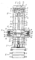
- the apparatus is composed of material sheet feed device a, end fusing device b, heating device c, and drawing device d which are arranged in a vertical row, and it is desired to obtain arbitrary drawing conditions by controlling the individual driving devices of the material sheet feed device a and drawing device d.
- the material sheet feed device a for feeding the material sheet glass G downward has a machine base 1 and a machine head 2 bonded and fixed at a specific interval by means of a post 3 to compose a machine frame.
- a ball screw 5 engaged with a first slide table 4 is inserted between the machine base 1 and machine head 2.
- the upper end of the ball screw 5 is borne by a bearing 6 of the machine head 2, while the lower end penetrates through a bearing 7 of the machine base 1 to project out, thereby causing a gear 8 at the lower end to be engaged with a gear 10 of a driving device 9.
- the slide table 4 engaged with the ball screw 5 ascends or descends at specific speed along the post 3.
- the first slide table 4 possesses an air cylinder 15 for opening and closing a chuck arm 14 integrally forming a first chuck 13 for holding the upper end of the material sheet glass G.
- This chuck arm 14 moves longitudinally in the horizontal direction by means of a motor 16 with respect to the first slide table 4, and the forward position is the delivery position of the material sheet glass G and the rear position is the specified feed position.
- Beneath the delivery position a loader 17 is installed.
- This loader 17 comprises, as shown in FIG. 3, an elevating table 17a, and a hoisting table 17c being hoisted by a cylinder 17b on this elevating table 17a, and it is designed to set upright the material sheet glass G being conveyed in the horizontal position, and elevate and insert into the first chuck 13.
- this device b comprises a second slide table 20 and a third slide table 30, and these slide tables 20, 30 are engaged with ball screws 23, 23a driven by a similar driving device as used in the first slide table 4 so as to be capable of ascending and descending along the post 3, and on the slide tables 20, 30 are mounted moving tables 24, 25, 35, 36 having a pair of second chucks 21, 22 and a pair of third chucks 31, 32 for holding the both ends of the material sheet glass G so as to be movable to be closer to and remoter from the both sides of the material sheet glass G by means of air cylinders 26, 27, 37, 38, and the second chucks 21, 22 and third chucks 31, 32 are opened and closed by air cylinders 28, 29, 39, 40. Or by omitting the moving tables 24, 25, 35, 36, the second chucks 21, 22 and third chucks 31, 32 may be directly mounted on the slide tables 20, 30.
- a fusion burner 33 for heating the end of the material sheet glass G is integrally fixed.
- the ball screws 5, 23, 23a for elevating the first to third slide tables 4, 20, 30 can be driven by mutually independent motors, but for the case of mutually synchronous actions, the driving device 9 uses, as shown in FIG. 4, two motors 9a, 9b for lowering action, and three motors 9c, 9d, 9e for raising action, and clutches 9f to 9n are provided by three pieces each for the motors 9a, 9b, 9c, 9d, 9e so as to be selected.
- the motor 9a always rotates at a same speed, and feeds the material sheet glass G into the heating device C at a specific speed (e.g. 120 mm/min).
- the motor 9b is for varying the feed speed of the material sheet glass G in each process, and it rotates at a higher speed than the motor 9a.
- the motor 9c, 9d, 9e are for ascending motion only, and are designed to raise the slide tables 4, 20, 30 at high speed.
- an encoder for measuring the moving speed (not shown) and an encoder for measuring the moving distance (not shown) are mounted on the shafts of the ball screws 5, 23, 23a.
- the heating device C consists of, as shown in FIG. 5, an elevatable bonding furnace 41, a stationary forming furnace 42 and an annealing furnace 43.
- the bonding furnace 41 is for insulating the fused portion of the material sheet glass G, and a plurality of heating elements 41a are disposed opposingly on both sides of the material sheet glass G, and these heating elements 41a are mounted on a support arm 41c by way of the support member 41b, and this support arm 41c is elevated and driven by an exclusive elevating device (not shown) along the post 3.
- the forming furnace 42 as shown in FIG. 6, has a slit 42a through which the material sheet glass G penetrates disposed in the middle position, and heating elements 42b are disposed so as to be opposite to both sides of the material sheet glass G passing through this slit 42a, and these heating elements 42b are arranged at small pitches so as to control the heating temperature in the widthwise direction of the material sheet glass G, and are fixed and installed on the floor on the whole.
- the annealing furnace 43 is continuously disposed to the lower part of the forming furnace 42, which prevents the material sheet glass G heated up to the softening temperature in the forming furnace 42 from being cooled abruptly in order to cool gradually, and structurally it is similar to the forming furnace 42, except that the density of arrangement of the heating elements is coarse in the feed direction of the material sheet glass G.
- the drawing device d having rollers for pulling the softened material sheet glass G by force is arranged in the vertical row.
- the material sheet glass G is inserted into the loader 17 in the horizontal position to be held, and the hoisting table 17c is raised upright by the cylinder 17b, and the material sheet glass G is set up vertically.
- the configuration at this time is that the first chuck 13 is at the forward delivery position, and that the material sheet glass G set upright by the hoisting table 17c is immediately beneath the first chuck 13.
- the elevating table 17a of the loader 17 is raised by a specific distance by the elevating cylinder (not shown), and the upper end of the material sheet glass G is inserted into the first chuck 13.
- the dimensions of the material sheet glass G being delivered are somewhat variable, and in order to fuse such material sheet glass G accurately, it is necessary to measure the position of the holding point accurately so as to hold securely without deviation.
- the first chuck 13 is lowered as shown in FIG. 7C, and when the end of the length measuring sensor Sl fitted to the first slide table 4 touches the upper end of the material sheet glass G and is pushed in by a preset amount, lowering of the first chuck 13 stops.
- the motor used at this time is 9b.
- the firt chuck 13 overruns somewhat, the difference between the value of the length measuring sensor Sl and the set value is stored.
- the first chuck 13 In succession, by the air cylinder 15, the first chuck 13 is closed, and the upper end of the material sheet glass G is held. As a result, the loader 17 releases the holding of the material sheet glass, and then descends, and raises the hoisting table 17c to be ready for delivery of the next material sheet glass G.
- the first chuck 13 withdraws to the backward position horizontally by means of the motor 16, and descends at high speed by means of the motor 9b until the lower end of the material sheet glass G reaches the heating device C, when the operation is changed over to the constant speed descending by the motor 9a.
- the second chucks 21, 22, and the third chucks 31, 32 are waiting at the ascending end.
- the ascending end of the second chucks 21, 22 and third chucks 31, 32 is set at a proper position between the ascending end and descending end of the first chuck, for example, near the middle position.
- the length measuring sensor S2 fitted to the first slide table 4 touches the uppper end of the third slide table 30 as shown in FIG. 7D and is pushed in by a preset extent, when the center of the fusing burner 33 and the upper end position of the material sheet glass G held by the third chucks 31, 32 are matched theoretically.
- the second chucks 21, 22 and third chucks 31, 32 are lowered by a speed synchronized with the first chuck 13 by means of the motor 9a, and in this descending process, the upper end of the material sheet glass G is held by the third chucks 31, 32.
- the holding position by the third chucks 31, 32 designed are designed in such a manner as to hold after correcting the stored value of the difference of the value of the length measuring sensor Sl and the set value as the first chuck 13 overruns in FIG. 7B, so as to diminish the effect of overrun of the first chuck 13 when holding the upper end of the material sheet glass G.
- the third chucks 31, 32 descends at specific speed by means of the motor 9a, and the material sheet glass G is supplied into the heating device C.
- the second chucks 21, 22 remain in released state, and descend at synchronous speed with the third chucks 31, 32 by means of the motor 9a, and in this descending stroke, the distance up to the upper end of the third slide table 30, that is, the distance between the second chucks 21, 22 and third chucks 31, 32 is measured by the length measuring sensor S3 mounted on the second slide table 20 as shown in FIG. 7E, and the difference from the set value is stored.
- the first chuck operates as explained in FIG. 7A to FIG. 7C, and receive the next material sheet glass G from the loader 17, thereby waiting at the delivery position ahead of the first slide table 4.
- the second chucks 21, 22 descend to a certain position
- the first chuck 13 moves to the backward position, and then descends at high speed by means of the motor 9b.
- the lower end of the material sheet glass G approaches the upper end of the preceding material sheet glass G.
- the high speed descending of the next material sheet glass G is changed over to specific speed descending by the motor 9b as the lower end pushes the length measuring sensor S4 of the second slide table 20 to the set value as shown in FIG.
- the first chuck 13 descends at a specific speed synchronized with the second chucks 21, 22 and third chucks 31, 32. At this time, if the first chuck 13 overruns beyond the set value of the length measuring sensor S4, it is immediately corrected.
- the first chuck 13 When the gap is reduced to the set value, the first chuck 13 is changed over to the motor 9a, and descends at specific speed synchronous with the second to third chucks 21, 22, 31, 32. In succession, the second chucks 21, 22 close, and hold the lower end of the next material sheet glass G.
- the third chucks 31, 32 descend to the specific position, the operation enters into the sealing process. Or, the sealing process may be started immediately after once measuring the gap.
- the first chuck 13 and the second chucks 21, 22 descend at high speed in synchronism by means of the motor 9b, and this gap is reduced to the set value (e.g. 2 mm), and the motor is changed over to 9a again, and they descend at specific speed synchronous with the third chucks 31, 32.
- the fusing burner 33 is ignited, and approaches to heat and soften the edges to be fused of the both glasses G, G. Consequently, the first chuck 13 and the second chucks 21, 22 are lowered at high speed by the motor 9b. This is in consideration of the gap mentioned above, and high speed descending is effected for the portion necessary for fusion of the edges of the both glasses G, G, and the operation is immediately changed over to the motor 9a so as to lower at a specific speed synchronous with the third chucks 31, 32. Consequently, the first chuck 13 and second chucks 21, 22 are momentarily stopped of lowering action, and thereafter they are lowered at specific speed synchronous with the third chucks 31, 32.
- the edges of the material sheet glasses G, G are heated and softened by the fusing burner 33, and are fused together by bringing closer to each other as shown in FIG. 8b, and thereafter the feed of the upper side material sheet glass G is stopped momentarily as shown in FIG. 8c, and the upper and lower material sheet glasses G, G are once pressed, and then pulled somewhat, and by this action, the built-up thickness of the glass fusion part becomes smooth as shown in FIG. 8b, and the dimensional fluctuation of the sheet after redrawing diminishes.
- the second chucks 21, 22 and the third chucks 31, 32 open, and return to the intermediate position to wait.
- the bonding furnace 41 of the heating device C ascends, after completion of fusion, so as to follow up the second chucks 21, 22 and third chucks 31, 32 so as not to cool the fused portion.
- the material sheet glass G to which the next material sheet glass G is fused in this way is held by the first chuck 13, and is sent into the heating device c at a specific speed, so that the fusion portion is also fed at specific speed.
- the elevated bonding furnace 41 of the heating device C is lowered at synchronous speed to maintain the fused portion at a constant temperature.
- the material sheet glass G is fed into the heating device c at specific speed, and is heated and softened in the forming furnace 42, and is gradually cooled in the annealing furnace 43, and is continuously redrawn into thin sheet glass of specified thickness by the drawing device 4.
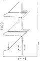
- FIG. 9 is an example of time chart at chuck points of the first to third slide tables.
- the descending end position of the first slide table overlaps with the ascending end position of the second slide table, and this is because it is expressed at the position of the chuck point of the first chuck 13.
Landscapes
- Chemical & Material Sciences (AREA)
- Engineering & Computer Science (AREA)
- Materials Engineering (AREA)
- Organic Chemistry (AREA)
- Joining Of Glass To Other Materials (AREA)
- Re-Forming, After-Treatment, Cutting And Transporting Of Glass Products (AREA)
Priority Applications (1)
| Application Number | Priority Date | Filing Date | Title |
|---|---|---|---|
| DE19883885282 DE3885282T2 (de) | 1988-02-22 | 1988-02-22 | Vorrichtung und verfahren dünner glasplatten. |
Applications Claiming Priority (1)
| Application Number | Priority Date | Filing Date | Title |
|---|---|---|---|
| PCT/JP1988/000188 WO1989007580A1 (fr) | 1988-02-22 | 1988-02-22 | Procede et dispositif de production de minces plaques de verre |
Publications (3)
| Publication Number | Publication Date |
|---|---|
| EP0360864A1 true EP0360864A1 (de) | 1990-04-04 |
| EP0360864A4 EP0360864A4 (de) | 1990-06-27 |
| EP0360864B1 EP0360864B1 (de) | 1993-10-27 |
Family
ID=13930545
Family Applications (1)
| Application Number | Title | Priority Date | Filing Date |
|---|---|---|---|
| EP88901935A Expired - Lifetime EP0360864B1 (de) | 1988-02-22 | 1988-02-22 | Vorrichtung und verfahren dünner glasplatten |
Country Status (4)
| Country | Link |
|---|---|
| US (1) | US4999039A (de) |
| EP (1) | EP0360864B1 (de) |
| KR (1) | KR950014690B1 (de) |
| WO (1) | WO1989007580A1 (de) |
Cited By (1)
| Publication number | Priority date | Publication date | Assignee | Title |
|---|---|---|---|---|
| EP0607433B2 (de) † | 1992-07-31 | 2003-03-05 | Shin-Etsu Quartz Products Co., Ltd. | Verfahren für die Herstellung einer Quartzglasscheibe mit grosser Abmessung und hoher Sauberkeit |
Families Citing this family (5)
| Publication number | Priority date | Publication date | Assignee | Title |
|---|---|---|---|---|
| US7231786B2 (en) * | 2004-07-29 | 2007-06-19 | Corning Incorporated | Process and device for manufacturing glass sheet |
| CN101090874B (zh) * | 2004-12-27 | 2011-03-02 | 古河电气工业株式会社 | 玻璃条的制造方法、玻璃条以及玻璃基板 |
| KR20120046734A (ko) * | 2009-08-07 | 2012-05-10 | 아사히 가라스 가부시키가이샤 | 초박판 유리 기판의 제조 방법 |
| JP5678509B2 (ja) * | 2010-08-02 | 2015-03-04 | 日本電気硝子株式会社 | 波長変換部材の製造方法、波長変換部材及び光源 |
| TW201223906A (en) * | 2010-10-08 | 2012-06-16 | Corning Inc | Strengthened glass enclosures and method |
Family Cites Families (4)
| Publication number | Priority date | Publication date | Assignee | Title |
|---|---|---|---|---|
| US3582305A (en) * | 1968-06-03 | 1971-06-01 | Owens Illinois Inc | Method and apparatus for the manufacture of a contoured redrawn glass article |
| JPS595530B2 (ja) * | 1976-01-12 | 1984-02-06 | 日本電気硝子株式会社 | 硝子元板を引き延ばして薄板を製造する方法及び装置 |
| FR2487811B1 (fr) * | 1980-07-31 | 1985-07-26 | France Etat | Procede et installation de fabrication de fibres optiques en continu |
| JPS595530A (ja) * | 1982-06-30 | 1984-01-12 | 松下電工株式会社 | 埋込型調光スイツチ |
-
1988
- 1988-02-22 WO PCT/JP1988/000188 patent/WO1989007580A1/ja not_active Ceased
- 1988-02-22 EP EP88901935A patent/EP0360864B1/de not_active Expired - Lifetime
- 1988-02-22 KR KR1019890701909A patent/KR950014690B1/ko not_active Expired - Fee Related
- 1988-02-22 US US07/425,209 patent/US4999039A/en not_active Expired - Fee Related
Cited By (1)
| Publication number | Priority date | Publication date | Assignee | Title |
|---|---|---|---|---|
| EP0607433B2 (de) † | 1992-07-31 | 2003-03-05 | Shin-Etsu Quartz Products Co., Ltd. | Verfahren für die Herstellung einer Quartzglasscheibe mit grosser Abmessung und hoher Sauberkeit |
Also Published As
| Publication number | Publication date |
|---|---|
| KR900700400A (ko) | 1990-08-13 |
| WO1989007580A1 (fr) | 1989-08-24 |
| US4999039A (en) | 1991-03-12 |
| EP0360864A4 (de) | 1990-06-27 |
| EP0360864B1 (de) | 1993-10-27 |
| KR950014690B1 (ko) | 1995-12-13 |
Similar Documents
| Publication | Publication Date | Title |
|---|---|---|
| US4691817A (en) | Feeder for introducing and feeding plates into a machine tool | |
| US4604124A (en) | Apparatus for manufacturing of tempered, bent glass sheets | |
| EP0593137B1 (de) | Verfahren zum Erhitzen einer Glasscheibe für laminiertes Glas | |
| EP0360864B1 (de) | Vorrichtung und verfahren dünner glasplatten | |
| CN110834153A (zh) | 一种自动上下料的激光打标设备 | |
| CN208696194U (zh) | 一种全自动螺母锻造机 | |
| CN111283433A (zh) | 一种铜带裁切成型装置及方法 | |
| WO2007023732A1 (ja) | 自動フープ供給システムを備えたインサート成形機 | |
| JP2000062023A (ja) | エンボスキャリアテープ成型機 | |
| JPS6355128A (ja) | 薄板ガラスの製造方法及び装置 | |
| JP3222590B2 (ja) | ガラスプレス品の製造装置およびその製造方法 | |
| CN108044685A (zh) | 养殖盘冲孔用的送料装置及养殖盘冲孔机 | |
| US3698619A (en) | Device for the manufacture of an insulating pane unit | |
| CN207757720U (zh) | 养殖盘冲孔用的送料装置及养殖盘冲孔机 | |
| JPH0446858B2 (de) | ||
| DE3885282T2 (de) | Vorrichtung und verfahren dünner glasplatten. | |
| CN212151016U (zh) | 一种前端自动送料3d热转印装置 | |
| CN211226893U (zh) | 一种玻璃热弯设备 | |
| JPWO1989007580A1 (ja) | 薄板ガラスの製造方法及び装置 | |
| CN115448581A (zh) | 一种用于再拉法制备柔性玻璃的装置 | |
| CN209178607U (zh) | 刹车片针刺机 | |
| JPH04157015A (ja) | 押出プレスのダイブロツク保温装置 | |
| KR940000576B1 (ko) | 직물 표면에의 스팡글 부착방법 및 그 장치 | |
| JPH0753222A (ja) | ガラス製品の成型方法及び成型装置 | |
| CN118681980B (zh) | 一种提升机链板热冲压装置 |
Legal Events
| Date | Code | Title | Description |
|---|---|---|---|
| PUAI | Public reference made under article 153(3) epc to a published international application that has entered the european phase |
Free format text: ORIGINAL CODE: 0009012 |
|
| 17P | Request for examination filed |
Effective date: 19891013 |
|
| AK | Designated contracting states |
Kind code of ref document: A1 Designated state(s): BE DE FR GB NL |
|
| RIN1 | Information on inventor provided before grant (corrected) |
Inventor name: KAIZUKA, TSUNEO Inventor name: YOSHIMURA,RYOUJI Inventor name: ITOI, HIDEYUKI |
|
| A4 | Supplementary search report drawn up and despatched |
Effective date: 19900627 |
|
| 17Q | First examination report despatched |
Effective date: 19920211 |
|
| GRAA | (expected) grant |
Free format text: ORIGINAL CODE: 0009210 |
|
| AK | Designated contracting states |
Kind code of ref document: B1 Designated state(s): BE DE FR GB NL |
|
| PG25 | Lapsed in a contracting state [announced via postgrant information from national office to epo] |
Ref country code: BE Effective date: 19931027 |
|
| REF | Corresponds to: |
Ref document number: 3885282 Country of ref document: DE Date of ref document: 19931202 |
|
| ET | Fr: translation filed | ||
| PG25 | Lapsed in a contracting state [announced via postgrant information from national office to epo] |
Ref country code: GB Effective date: 19940222 |
|
| PLBE | No opposition filed within time limit |
Free format text: ORIGINAL CODE: 0009261 |
|
| STAA | Information on the status of an ep patent application or granted ep patent |
Free format text: STATUS: NO OPPOSITION FILED WITHIN TIME LIMIT |
|
| PG25 | Lapsed in a contracting state [announced via postgrant information from national office to epo] |
Ref country code: NL Effective date: 19940901 |
|
| NLV4 | Nl: lapsed or anulled due to non-payment of the annual fee | ||
| 26N | No opposition filed | ||
| GBPC | Gb: european patent ceased through non-payment of renewal fee |
Effective date: 19940222 |
|
| PGFP | Annual fee paid to national office [announced via postgrant information from national office to epo] |
Ref country code: FR Payment date: 20020212 Year of fee payment: 15 |
|
| PGFP | Annual fee paid to national office [announced via postgrant information from national office to epo] |
Ref country code: DE Payment date: 20020306 Year of fee payment: 15 |
|
| PG25 | Lapsed in a contracting state [announced via postgrant information from national office to epo] |
Ref country code: DE Free format text: LAPSE BECAUSE OF NON-PAYMENT OF DUE FEES Effective date: 20030902 |
|
| PG25 | Lapsed in a contracting state [announced via postgrant information from national office to epo] |
Ref country code: FR Free format text: LAPSE BECAUSE OF NON-PAYMENT OF DUE FEES Effective date: 20031031 |
|
| REG | Reference to a national code |
Ref country code: FR Ref legal event code: ST |