EP0360253A2 - Enthaarungsvorrichtung - Google Patents
Enthaarungsvorrichtung Download PDFInfo
- Publication number
- EP0360253A2 EP0360253A2 EP89117414A EP89117414A EP0360253A2 EP 0360253 A2 EP0360253 A2 EP 0360253A2 EP 89117414 A EP89117414 A EP 89117414A EP 89117414 A EP89117414 A EP 89117414A EP 0360253 A2 EP0360253 A2 EP 0360253A2
- Authority
- EP
- European Patent Office
- Prior art keywords
- engagement
- elongate elements
- hair
- mutually twisted
- twisted
- Prior art date
- Legal status (The legal status is an assumption and is not a legal conclusion. Google has not performed a legal analysis and makes no representation as to the accuracy of the status listed.)
- Ceased
Links
Images


Classifications
-
- A—HUMAN NECESSITIES
- A61—MEDICAL OR VETERINARY SCIENCE; HYGIENE
- A61B—DIAGNOSIS; SURGERY; IDENTIFICATION
- A61B17/00—Surgical instruments, devices or methods
-
- A—HUMAN NECESSITIES
- A45—HAND OR TRAVELLING ARTICLES
- A45D—HAIRDRESSING OR SHAVING EQUIPMENT; EQUIPMENT FOR COSMETICS OR COSMETIC TREATMENTS, e.g. FOR MANICURING OR PEDICURING
- A45D26/00—Hair-singeing apparatus; Apparatus for removing superfluous hair, e.g. tweezers
Definitions
- the present invention relates to depilatory devices and techniques generally and more particularly to powered mechanical depilatory devices.
- an electrically powered depilatory device including a hand held portable housing, motor apparatus disposed in the housing, and a helical spring comprising a plurality of adjacent windings arranged to be driven by the motor apparatus in rotational sliding motion relative to the skin bearing hair to be removed, the helical spring including an arcuate hair engaging portion arranged to define a convex side whereat the windings are spread apart and a concave side corresponding thereto whereat the windings are pressed together, the rotational motion of the helical spring producing continuous motion of the windings from a spread apart orientation at the convex side to a pressed together orientation at the concave side for engagement and plucking of hair from the skin, whereby the surface velocities of the windings relative to the hair greatly exceed the surface velocity of the housing relative thereto.
- the present invention seeks to provide a mechanical depilatory device which differs from the prior art devices described above and which provides efficient and relatively painless hair removal.
- an electrically powered depilatory device including a hand held portable housing, a hair engagement and removal assembly including elongate elements in mutually twisted engagement, and motor apparatus for driving the elongate elements in motion, whereby hair is engaged between the elongate elements and thus removed.
- the action of the mutually twisted elongate elements when driven by the motor apparatus is to wind hair in engagement therewith.
- the motion of the elongate elements is such that the hair is wound in engagement with the elongate elements at a location separated from the location at which it is initially engaged thereby.
- the elongate elements form part of a single endless loop.
- the elongate elements may be embodied in two or more separate endless loops.
- the motor apparatus is operative to draw the elongate elements through the twisted engagement, whereby given regions of the elongate elements enter mutually twisted engagement and subsequently leave such engagement. Normally the locations at which given regions of the elongate elements enter and leave mutually twisted engagement are spaced from each other.
- the arrangement of the elongate elements in mutually twisted engagement and the driving thereof by the motor apparatus is such that the elongate elements move forward in a generally spiral type motion and rotate about their elongate axes as they move through mutually twisted engagement.
- the arrangement of the elongate elements in mutually twisted engagement is such that when driven by the motor apparatus, the engagement and removal assembly undergoes continuous twisting action.
- the arrangement of the engagement and removal assembly is such that the location of the twisted engagement remains generally static relative to the housing.
- the twisted engagement comprises multiple coils, preferably at least two in number.
- the arrangement of the engagement and removal assembly is such that the twisted engagement extends generally linearly.
- the twisted engagement is provided by twisting together elongate elements forming part of one or more endless loops.
- the elongate elements are maintained in the twisted engagement by means of rollers.
- the twisted engagement is provided by twisting together elongate elements and subsequently joining them to form one or more endless loops.
- rollers are not needed to maintain the elongate elements in twisted engagement.
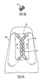
- Figs. 1A and 1B illustrate in respective plan and sectional view, a depilatory device constructed and operative in accordance with a preferred embodiment of the invention.
- the depilatory device comprises a hand-held portable housing 10 having formed therein a hair engagement and removal assembly 12, which is seen through an access opening 14 in housing 10.
- the hair engagement and removal assembly 12 comprises elongate elements arranged in mutually twisted engagement, as seen at reference numeral 16.
- the elongate elements which preferably form part of a single endless loop of flexible material, such as silicone rubber, are driven by means, not shown in Figs. 1A and 1B, examples of which are described in detail hereinbelow, so as to enter, pass through and leave mutually twisted engagement, as indicated by the arrows in Fig. 1A. It will be appreciated that motion of the elongate elements in an opposite direction to that illustrated is also possible.
- the elongate elements may alternatively be formed of other materials such as plastics, other rubbers, and natural or synthetic fibers such as cotton.
- the elongate elements 16 are typically twisted and then subsequently joined to define the endless loop.
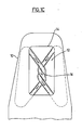
- Fig. 1C illustrates an alternative embodiment of the invention which is identical to that of Figs. 1A and 1B except that the twisted engagement comprises only a single coil.
- the motion of the elongate elements in mutually twisted engagement as illustrated is operative to engage hair between the elongate elements and to remove such hair from the skin.
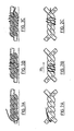
- Two examples, which are not necessarily exclusive, of the operation of hair removal by the apparatus of Figs. 1A and 1B are illustrated in Figs. 2A - 5C, in which the thickness of the hair is exaggerated for the sake of clarity.
- FIGS. 2A, 2B, 2C, 3A, 3B and 3C illustrate one example of hair removal action in accordance with the present invention.
- Figs. 2A and 3A illustrate a hair about to be engaged in mutually twisted elongate elements, which are driven in the directions illustrated therein, including both motion along the elongate extent of the elements as illustrated by the arrows in Fig. 2A, and rotational motion of the elements as the enter, pass through and leave mutually twisted engagement.
- Figs. 2B and 3B illustrate the hair being wound in engagement with the mutually twisted elongate elements, as they progress in the general direction indicated by the arrow 20 in Fig. 2B.
- Figs. 2C and 3C illustrate the wound hair after it has been removed from its root location in the skin and has moved forward in the general direction of the arrow 20 in Fig. 2B. The removed hair disengages from the elongate elements as they leave mutually twisted engagement.
- FIGS. 4A, 4B, 4C, 5A, 5B and 5C illustrate another example of hair removal action in accordance with the present invention.
- Figs. 4A and 5A illustrate a hair about to be engaged in mutually twisted elongate elements, and correspond generally to Figs. 2A and 3A.
- Figs. 4B and 5B illustrate the hair twisted together with the elongate elements, as opposed to being twisted thereover as shown in Figs. 2B and 3B.
- Figs. 3C and 5C show the wound hair removed from the root location on the skin and displaced from the root location.
- the actual hair removal operation of the apparatus of the invention may vary depending on a variety of conditions, including inter alia, the type and length of hair, the speed at which the elongate elements move into and through mutually twisted engagement, the location at which the hair is engaged relative to the engagement and removal assembly and relative to the root location.
- the type and length of hair including inter alia, the speed at which the elongate elements move into and through mutually twisted engagement, the location at which the hair is engaged relative to the engagement and removal assembly and relative to the root location.
- the hair engagement and removal assembly of the present invention is operative to remove hair by both winding it and displacing the wound hair from the root, thus resulting in double action hair removal.
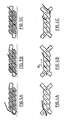
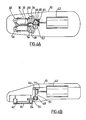
- Figs. 6A and 6B illustrate a preferred embodiment of the depilatory apparatus of the present invention. It will be appreciated that in Figs. 6A - 11, the entire hair engagement and removal assembly including the mounting and driving thereof is shown for the sake of clarity. In reality, parts of the hair engagement and removal assembly will be enclosed by the housing, as shown, for example in Fig. 1A.
- the hair engagement and removal assembly comprises a single endless loop 30.
- the loop is configured to define a region 32 in which the two elongate elements or portions of the loop are engaged in mutually twisted engagement.
- a linear twisted engagement of two coils is shown. It is appreciated that alternatively non-linear twisted engagements, as well as twisted engagements having a greater or lesser number of coils may be provided.
- Endless loop 30 is typically mounted at four corners onto rollers 34, 36, 38 and 40, as shown, which are rotatably mounted onto housing 10.
- An electric motor 42 receiving power from a source of electric power, not shown, drives rollers 34 and 38 in opposite directions, as illustrated, typically by means of engaging bevel gears 44 and 46, a drive gear 48 connected to bevel gear 46 by a shaft 50, a reversing gear 52, and roller drive gears 54 and 56, which drive respective rollers 34 and 38 and are driven by respective gears 48 and 52.
- Figs. 7A and 7B illustrate a depilatory device similar in operation to that of Figs. 6A and 6B but different in configuration, in that a generally upright housing is employed and a motor output shaft 60 lies in a plane generally perpendicular to that of the hair engagement and removal assembly 12.
- the hair engagement and removal assembly 12 may be identical to that shown in Figs. 6A and 6B and is here identified by identical reference numerals.
- the gear connections to the motor are somewhat simplified, in that the bevel gears are eliminated and a motor output drive gear 62 directly engages gear 44, which, in turn, drives gears 52 and 54.
- FIG. 8 illustrates a depilatory device which may be identical to that of Figs. 6A and 6B but has two hair engagement and removal assemblies 12, rather than a single such assembly as in the embodiment of Figs. 6A and 6B.
- a motor 42 drives both assemblies 12 via bevel gears 44 and 46 and a drive gear 48.
- Drive gear 48 engages a roller drive gear 70, which in turn drivingly engages roller drive gears 72 and 74.
- Roller drive gear 74 in turn drives roller drive gear 76.
- the directions of motion of the two endless loops 30 are typically as shown, although the directions of one or both may be reversed, by suitable modification of the gearing.
- Figs. 9A and 9B illustrate a modular head depilatory device which includes a driver portion 80 and a replaceable head portion 82.
- the two portions may be removably snap fit together and the motor drive may be removably coupled by means of a removable snap fit rotary drive connection assembly including a male element 84 and a female element 86 as illustrated.
- a removable snap fit rotary drive connection assembly including a male element 84 and a female element 86 as illustrated.
- any other suitable type of coupling assembly may be employed.
- the hair engagement and removal assembly 12 may be identical to that shown in Figs. 6A and 6B.
- FIGs. 10 and 11 illustrate a depilatory device constructed and operative in accordance with a further alternative embodiment of the invention in which two endless loops 90 and 92 are employed.
- a motor 42 provides a rotary output via bevel gears 44 and 46 and a drive gear 48.
- Drive gear 48 drivingly engages a roller drive gear 94 for rotating it in a first direction, such as the direction indicated by arrow 96.
- Roller drive gear 94 drivingly engages roller drive gears 98 and 100, driving them in an opposite sense to the rotation of gear 94, as indicated by respective arrows 102 and 104.
- Roller drive gear 94 drives a roller 106 together therewith.
- Roller 106 drivingly supports both endless loops 90 and 92, which are also supported on a roller 108, driving them in opposite directions, as indicated by the arrows placed alongside the loops.
- Loop 90 is additionally supported on rollers 107 and 109, while loop 92 is additionally supported on rollers 111 and 113.
- Roller 113 is driven by roller drive gear 98, while roller 109 is driven by roller drive gear 100.
- FIG. 12 illustrates a depilatory device constructed and operative in accordance with a further alternative embodiment of the invention in which two endless loops 110 and 112 are employed.
- Loops 110 and 112 are typically untwisted endless loops which are subsequently twisted together to define a twisted engagement, indicated generally by reference numeral 114.
- Loops 110 and 112 are typically maintained in the desired twisted engagement 114 by means of a pair of rollers 116 and 118 which are pivotably mounted onto a housing 120.
- Loop 110 is mounted onto rollers 122 and 124, while loop 112 is mounted onto rollers 126 and 128. All of rollers 122 - 128 are rotatably mounted onto housing 120.
- An electric motor 130 drives rollers 124 and 128 via bevel gears 132 and 134, intermediate drive gears 136 and 138 and drive gears 140 and 142, associated with respective rollers 124 and 128.
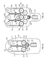
- Fig. 13 illustrates a depilatory device constructed and operative in accordance with yet another alternative embodiment of the invention in which a single endless loop 150 is employed.
- loop 150 is typically an untwisted endless loop which is subsequently twisted.
- loop 150 is twisted at two separate locations to define first and second twisted engagements, indicated generally by reference numeral 152 and 154.
- Loop 150 is supported on six rollers, indicated by reference numerals 156, 158, 160, 162, 164 and 166.
- the twisted engagements 152 and 154 are each maintained by respective roller pairs 167 and 168, and 170 and 172, as illustrated. All of the rollers 156 - 172 are pivotably mounted onto a housing 180.
- An electric motor 190 drives rollers 158, 162 and 166 via bevel gears 192 and 194, intermediate drive gears 196, 198 and 200 and drive gears 202, 204 and 206, associated with respective rollers 158, 162 and 166.
Landscapes
- Health & Medical Sciences (AREA)
- Life Sciences & Earth Sciences (AREA)
- Surgery (AREA)
- Heart & Thoracic Surgery (AREA)
- Engineering & Computer Science (AREA)
- Biomedical Technology (AREA)
- Nuclear Medicine, Radiotherapy & Molecular Imaging (AREA)
- Medical Informatics (AREA)
- Molecular Biology (AREA)
- Animal Behavior & Ethology (AREA)
- General Health & Medical Sciences (AREA)
- Public Health (AREA)
- Veterinary Medicine (AREA)
- Surgical Instruments (AREA)
- Hair Curling (AREA)
Applications Claiming Priority (2)
| Application Number | Priority Date | Filing Date | Title |
|---|---|---|---|
| IL87833 | 1988-09-22 | ||
| IL87833A IL87833A0 (en) | 1988-09-22 | 1988-09-22 | Depilatory device |
Publications (2)
| Publication Number | Publication Date |
|---|---|
| EP0360253A2 true EP0360253A2 (de) | 1990-03-28 |
| EP0360253A3 EP0360253A3 (de) | 1990-05-30 |
Family
ID=11059265
Family Applications (1)
| Application Number | Title | Priority Date | Filing Date |
|---|---|---|---|
| EP89117414A Ceased EP0360253A3 (de) | 1988-09-22 | 1989-09-20 | Enthaarungsvorrichtung |
Country Status (6)
| Country | Link |
|---|---|
| US (1) | US4983175A (de) |
| EP (1) | EP0360253A3 (de) |
| JP (1) | JPH02124104A (de) |
| KR (1) | KR900004309A (de) |
| BR (1) | BR8904703A (de) |
| IL (1) | IL87833A0 (de) |
Cited By (3)
| Publication number | Priority date | Publication date | Assignee | Title |
|---|---|---|---|---|
| US7235085B1 (en) * | 2004-09-27 | 2007-06-26 | Tahir Shaheen F | Hair removal apparatus |
| WO2011103607A1 (de) | 2010-02-25 | 2011-09-01 | Kathrin Hackl | Vorrichtung zum entfernen von haaren |
| US9320334B2 (en) | 2011-06-16 | 2016-04-26 | Sweet Tea Innovations, Llc | Hair removal apparatus |
Families Citing this family (13)
| Publication number | Priority date | Publication date | Assignee | Title |
|---|---|---|---|---|
| JP2533681Y2 (ja) * | 1991-10-21 | 1997-04-23 | 株式会社マキタ | 継手用溝掘り機 |
| US5643287A (en) * | 1996-05-09 | 1997-07-01 | Capehead Enterprises, Inc. | Depilatory device |
| US5908425A (en) * | 1997-09-22 | 1999-06-01 | Adam; Helen | Depilatory device and method of use |
| US5951573A (en) * | 1998-05-15 | 1999-09-14 | Yashar; Parviz | Manual depilatory device |
| CA2421950A1 (en) * | 2000-09-08 | 2002-03-14 | James E. Coleman | Surgical staple |
| US20040219533A1 (en) * | 2003-04-29 | 2004-11-04 | Jim Davis | Biological bar code |
| US20090012535A1 (en) * | 2007-05-15 | 2009-01-08 | Sun Anita Schu-Chiam | Epilation device |
| US8029517B2 (en) * | 2007-05-15 | 2011-10-04 | Karmissie, Llc | Epilation device |
| JP2009291573A (ja) * | 2008-06-03 | 2009-12-17 | Hisashi Fukuda | 毛抜き |
| GB2461878A (en) * | 2008-07-15 | 2010-01-20 | Iram Khan | Hand-held device for threading of facial hair |
| EP2391237A1 (de) * | 2009-01-29 | 2011-12-07 | Karmissie, LLC. | Individuell befestigte einwegfäden auf einem fadenrahmen für epiliergerät oder fadenepiliergerät |
| CA2669971A1 (en) * | 2009-06-22 | 2010-12-22 | Sivashanthan Sivapalan | Method and apparatus for self-threading |
| CA2826951C (en) * | 2013-09-13 | 2021-02-23 | Asani Threading Inc. | Epilation device |
Family Cites Families (41)
| Publication number | Priority date | Publication date | Assignee | Title |
|---|---|---|---|---|
| US1232617A (en) * | 1916-01-25 | 1917-07-10 | John L Shipp | Spring hair-remover. |
| GB203970A (en) * | 1922-12-13 | 1923-09-20 | Charles Davis | Improvements in depilatory apparatus |
| GB225445A (en) * | 1924-03-27 | 1924-12-04 | Chin Leong Li | Improvements in and relating to hair removing instruments |
| US1875980A (en) * | 1927-11-23 | 1932-09-06 | Ringham George Cowley | Machine for plucking birds |
| US1743590A (en) * | 1928-11-14 | 1930-01-14 | Binz Matilde | Hair puller |
| FR667265A (fr) * | 1929-01-11 | 1929-10-15 | Appareil à plumer les volailles | |
| US1923415A (en) * | 1930-12-11 | 1933-08-22 | Bingham George Cowley | Machine for plucking and stubbing birds |
| CH179261A (fr) * | 1934-11-07 | 1935-08-31 | Macioce Michel | Appareil dépilatoire. |
| US2083380A (en) * | 1935-01-07 | 1937-06-08 | Wm Meyer Company | Device for shaping eyebrows and the like |
| FR788130A (fr) * | 1935-04-02 | 1935-10-04 | Commande automatique et alternative des pinces des tourteaux rotatifs | |
| US2112230A (en) * | 1935-10-21 | 1938-03-29 | James M Stockett | Feather plucking machine |
| US2458911A (en) * | 1944-08-29 | 1949-01-11 | Kerr Ellen | Device for depilatory purposes |
| US2592484A (en) * | 1946-06-15 | 1952-04-08 | Moreton A Smith | Power-driven tweezer |
| US2496223A (en) * | 1946-07-13 | 1950-01-31 | Joseph C Lanzisera | Poultry plucker |
| US2423245A (en) * | 1946-11-09 | 1947-07-01 | Carl E Magnus | Method of and device for extracting hairs by using adhesive tape |
| US2486616A (en) * | 1947-11-22 | 1949-11-01 | Carl J Schubiger | Hair tweezer |
| CH268696A (de) * | 1948-09-02 | 1950-05-31 | Fischer Rudolf | Haarentfernungsapparat. |
| DE845847C (de) * | 1950-01-27 | 1952-08-07 | Willy A Bachofen | Maschine zum Rupfen von Gefluegel |
| FR1017490A (fr) * | 1950-01-27 | 1952-12-11 | Machine à plumer la volaille | |
| FR1123971A (fr) * | 1955-05-11 | 1956-10-02 | Perfectionnements aux machines à plumer les volailles | |
| FR1151495A (fr) * | 1956-03-05 | 1958-01-30 | Machine à plumer la volaille | |
| US2900661A (en) * | 1957-03-11 | 1959-08-25 | Schnell Carl | Plucking device for feathers, hairs or the like |
| US3150409A (en) * | 1963-04-10 | 1964-09-29 | Frederick F Wilcox | Dehairing and skinning device |
| US3613690A (en) * | 1969-07-25 | 1971-10-19 | Francis Lee Newell | Hair removal tool |
| FR2126084A1 (de) * | 1971-02-24 | 1972-10-06 | Warde Jacques | |
| US3911530A (en) * | 1973-02-05 | 1975-10-14 | James S Kalfsbeek | System and method for removing feathers from ducks and other fowl |
| FR2245314A1 (en) * | 1973-10-02 | 1975-04-25 | Amstutz Daniel | Mechanical device for depilation of superfluous hair - has two rotating bands which frictionally grip and pull out hairs |
| FR2307491A1 (fr) * | 1975-04-15 | 1976-11-12 | Dzikowski Francis | Appareil a epiler automatique |
| GB1508528A (en) * | 1975-12-09 | 1978-04-26 | Daar Y | Apparatus for plucking hair from skin |
| US4171701A (en) * | 1977-07-01 | 1979-10-23 | Clairol Incorporated | Tweezer |
| NL7805230A (nl) * | 1978-05-16 | 1979-11-20 | Philips Nv | Epileerapparaat. |
| FR2454283A1 (fr) * | 1979-04-18 | 1980-11-14 | Lamy Perret Emile | Appareil a epiler les duvets |
| IE54383B1 (en) * | 1982-08-20 | 1989-09-13 | Improver Corp | Apparatus for hair removal |
| CH652899A5 (en) * | 1983-04-11 | 1985-12-13 | Reine Damiani | Hair-removing apparatus |
| FR2556939B1 (fr) * | 1983-12-22 | 1987-10-23 | Jean Alazet | Appareil a epiler |
| FR2588732B1 (fr) * | 1985-10-23 | 1991-02-08 | Alazet Jean | Appareil a epiler |
| FR2598067A1 (fr) * | 1986-05-02 | 1987-11-06 | Guillon Robert | Appareil pour pratiquer l'epilation |
| EP0270222A1 (de) * | 1986-10-10 | 1988-06-08 | Jal Hammoudi Jabouri | Haarentfernungsmechanismus |
| IL81780A (en) * | 1987-03-04 | 1988-09-30 | Hair Remover Ltd | Depilatory device for removing hair |
| IL81779A0 (en) * | 1987-03-04 | 1987-10-20 | Gross Joseph | Depilatory device |
| IL82002A0 (en) * | 1987-03-25 | 1987-10-20 | Gen Ideas & Prod Ltd | Depilatory device |
-
1988
- 1988-09-22 IL IL87833A patent/IL87833A0/xx not_active IP Right Cessation
-
1989
- 1989-09-11 US US07/405,888 patent/US4983175A/en not_active Expired - Fee Related
- 1989-09-19 BR BR898904703A patent/BR8904703A/pt unknown
- 1989-09-20 EP EP89117414A patent/EP0360253A3/de not_active Ceased
- 1989-09-21 JP JP1243575A patent/JPH02124104A/ja active Pending
- 1989-09-21 KR KR1019890013584A patent/KR900004309A/ko not_active Withdrawn
Cited By (3)
| Publication number | Priority date | Publication date | Assignee | Title |
|---|---|---|---|---|
| US7235085B1 (en) * | 2004-09-27 | 2007-06-26 | Tahir Shaheen F | Hair removal apparatus |
| WO2011103607A1 (de) | 2010-02-25 | 2011-09-01 | Kathrin Hackl | Vorrichtung zum entfernen von haaren |
| US9320334B2 (en) | 2011-06-16 | 2016-04-26 | Sweet Tea Innovations, Llc | Hair removal apparatus |
Also Published As
| Publication number | Publication date |
|---|---|
| EP0360253A3 (de) | 1990-05-30 |
| IL87833A0 (en) | 1989-03-31 |
| JPH02124104A (ja) | 1990-05-11 |
| US4983175A (en) | 1991-01-08 |
| BR8904703A (pt) | 1990-05-01 |
| KR900004309A (ko) | 1990-04-12 |
Similar Documents
| Publication | Publication Date | Title |
|---|---|---|
| US4983175A (en) | Depilatory device | |
| EP0101656B1 (de) | Enthaarungsgerät | |
| US4027348A (en) | Skin treatment appliance | |
| EP0549051B1 (de) | Haarentfernungsgerät mit verdrehender Wirkung | |
| US5057115A (en) | Hair removal device with improved coupled-disc element | |
| MXPA04006334A (es) | Aparato electrico para pulido de cabello. | |
| US5078715A (en) | Depilatory device | |
| EP0330091A2 (de) | Enthaarungsvorrichtung | |
| JP3271876B2 (ja) | 脱毛装置 | |
| JPH0429364B2 (de) | ||
| WO1995001149A1 (en) | Massaging equipment with an endless massage belt | |
| NZ205082A (en) | Electrically powered hair removal device with a loop-shaped helical spring | |
| CN2137138Y (zh) | 保健自动牙刷 | |
| GB2038691A (en) | Electric razor | |
| JPH01297002A (ja) | 毛を抜取るための脱毛器 | |
| JP2004049883A (ja) | 脱毛器及びこれに用いられるコイルスプリング |
Legal Events
| Date | Code | Title | Description |
|---|---|---|---|
| PUAI | Public reference made under article 153(3) epc to a published international application that has entered the european phase |
Free format text: ORIGINAL CODE: 0009012 |
|
| AK | Designated contracting states |
Kind code of ref document: A2 Designated state(s): AT BE CH DE ES FR GB GR IT LI LU NL SE |
|
| PUAL | Search report despatched |
Free format text: ORIGINAL CODE: 0009013 |
|
| AK | Designated contracting states |
Kind code of ref document: A3 Designated state(s): AT BE CH DE ES FR GB GR IT LI LU NL SE |
|
| 17P | Request for examination filed |
Effective date: 19900822 |
|
| 17Q | First examination report despatched |
Effective date: 19911129 |
|
| STAA | Information on the status of an ep patent application or granted ep patent |
Free format text: STATUS: THE APPLICATION HAS BEEN REFUSED |
|
| 18R | Application refused |
Effective date: 19930318 |