EP0360167B1 - Vehicle deceleration warning piezo-sensor - Google Patents
Vehicle deceleration warning piezo-sensor Download PDFInfo
- Publication number
- EP0360167B1 EP0360167B1 EP89117096A EP89117096A EP0360167B1 EP 0360167 B1 EP0360167 B1 EP 0360167B1 EP 89117096 A EP89117096 A EP 89117096A EP 89117096 A EP89117096 A EP 89117096A EP 0360167 B1 EP0360167 B1 EP 0360167B1
- Authority
- EP
- European Patent Office
- Prior art keywords
- housing
- contact
- accelerator pedal
- crystal
- pedal
- Prior art date
- Legal status (The legal status is an assumption and is not a legal conclusion. Google has not performed a legal analysis and makes no representation as to the accuracy of the status listed.)
- Expired - Lifetime
Links
- 230000004044 response Effects 0.000 claims abstract description 14
- 239000013078 crystal Substances 0.000 claims description 64
- 230000000994 depressogenic effect Effects 0.000 claims description 10
- 230000008859 change Effects 0.000 claims description 2
- 230000001419 dependent effect Effects 0.000 abstract description 2
- 230000004913 activation Effects 0.000 description 6
- 239000000463 material Substances 0.000 description 6
- 230000003247 decreasing effect Effects 0.000 description 4
- 230000000694 effects Effects 0.000 description 4
- 230000008901 benefit Effects 0.000 description 3
- 238000004519 manufacturing process Methods 0.000 description 3
- 239000004033 plastic Substances 0.000 description 3
- 239000003990 capacitor Substances 0.000 description 2
- 230000007423 decrease Effects 0.000 description 2
- 238000010586 diagram Methods 0.000 description 2
- 238000009434 installation Methods 0.000 description 2
- 230000001012 protector Effects 0.000 description 2
- 239000007787 solid Substances 0.000 description 2
- 241000282461 Canis lupus Species 0.000 description 1
- 241000283070 Equus zebra Species 0.000 description 1
- 229920004142 LEXAN™ Polymers 0.000 description 1
- 101100030469 Schizosaccharomyces pombe (strain 972 / ATCC 24843) ppk21 gene Proteins 0.000 description 1
- 239000000853 adhesive Substances 0.000 description 1
- 230000001070 adhesive effect Effects 0.000 description 1
- 230000033228 biological regulation Effects 0.000 description 1
- 239000000919 ceramic Substances 0.000 description 1
- 229910010293 ceramic material Inorganic materials 0.000 description 1
- 238000006243 chemical reaction Methods 0.000 description 1
- 239000004020 conductor Substances 0.000 description 1
- 230000008878 coupling Effects 0.000 description 1
- 238000010168 coupling process Methods 0.000 description 1
- 238000005859 coupling reaction Methods 0.000 description 1
- 230000001934 delay Effects 0.000 description 1
- 230000004069 differentiation Effects 0.000 description 1
- 239000013536 elastomeric material Substances 0.000 description 1
- 235000015220 hamburgers Nutrition 0.000 description 1
- 238000003780 insertion Methods 0.000 description 1
- 230000037431 insertion Effects 0.000 description 1
- 239000011810 insulating material Substances 0.000 description 1
- 239000002184 metal Substances 0.000 description 1
- 238000000034 method Methods 0.000 description 1
- 230000002265 prevention Effects 0.000 description 1
- 230000035484 reaction time Effects 0.000 description 1
- 230000009467 reduction Effects 0.000 description 1
- 230000008439 repair process Effects 0.000 description 1
- 230000035939 shock Effects 0.000 description 1
- 229910001220 stainless steel Inorganic materials 0.000 description 1
- 239000010935 stainless steel Substances 0.000 description 1
- 230000001052 transient effect Effects 0.000 description 1
Images




Classifications
-
- B—PERFORMING OPERATIONS; TRANSPORTING
- B60—VEHICLES IN GENERAL
- B60Q—ARRANGEMENT OF SIGNALLING OR LIGHTING DEVICES, THE MOUNTING OR SUPPORTING THEREOF OR CIRCUITS THEREFOR, FOR VEHICLES IN GENERAL
- B60Q1/00—Arrangement of optical signalling or lighting devices, the mounting or supporting thereof or circuits therefor
- B60Q1/26—Arrangement of optical signalling or lighting devices, the mounting or supporting thereof or circuits therefor the devices being primarily intended to indicate the vehicle, or parts thereof, or to give signals, to other traffic
- B60Q1/44—Arrangement of optical signalling or lighting devices, the mounting or supporting thereof or circuits therefor the devices being primarily intended to indicate the vehicle, or parts thereof, or to give signals, to other traffic for indicating braking action or preparation for braking, e.g. by detection of the foot approaching the brake pedal
- B60Q1/441—Electric switches operable by the driver's pedals
-
- Y—GENERAL TAGGING OF NEW TECHNOLOGICAL DEVELOPMENTS; GENERAL TAGGING OF CROSS-SECTIONAL TECHNOLOGIES SPANNING OVER SEVERAL SECTIONS OF THE IPC; TECHNICAL SUBJECTS COVERED BY FORMER USPC CROSS-REFERENCE ART COLLECTIONS [XRACs] AND DIGESTS
- Y10—TECHNICAL SUBJECTS COVERED BY FORMER USPC
- Y10S—TECHNICAL SUBJECTS COVERED BY FORMER USPC CROSS-REFERENCE ART COLLECTIONS [XRACs] AND DIGESTS
- Y10S188/00—Brakes
- Y10S188/01—Panic braking
Definitions
- the present invention relates to a vehicle deceleration warning apparatus which would provide early warning of an impending stop by advance brake light activation, prior to actuation of the brake pedals.
- CHMSL center-high-mounted-stop lamp
- Mortimer discloses an accelerator release signal light delay actuator which delays actuation of the brake light upon release of the driver's foot from the accelerator pedal for 5 or 6 seconds following release of the accelerator. After the delay period is past, if the brake has not yet been applied, the brake lights are turned on at an intensity less than the intensity available when the brakes are actually actuated. Thus, the possibility of false indication is decreased since the person behind the front car recognizes the decreased intensity of the light indicating that the brake has not itself been actuated.
- Morehouse discloses an automobile deceleration warning system in which an auxiliary pedal is positioned above the main accelerator pedal.
- a normally opened switch is positioned between the two pedals. Upon release of the auxiliary pedal, the switch closes, thereby lighting the brake light.
- a resistor may be included which reduces the current flow to the brake lights, thus lighting the brake lights at a lower intensity when the lights are actuated in response to the lifting of the accelerator pedal as compared with the intensity of the brake lights when the brakes are actually applied.
- the Shames patents disclose a vehicle brake light warning system in which the brake lights are activated for a given period of time upon release of the accelerator pedal. This time period is sufficient for the driver to lift his foot from the accelerator to the brake pedal. If the brakes are not applied within that time period, the brake lights are turned off.
- European Patent No. 0 219 858 discloses a device which remains ineffective in non-emergency cases.
- the advanced braking light device (ABLD) is an electronic device installed on a vehicle accelerator pedal. When a leading vehicle driver attempts a panic-braking operation, the accelerator pedal is released by a sudden movement when the driver's leg is shifted to apply the brake pedal as quickly as possible.
- the sudden release is sensed by the ABLD and immediately after the accelerator pedal is released, the stop lights are activated.
- This advanced activation of the stop lights by a fraction of 0.2-0.3 seconds, which is approximately the time necessary for the driver to move his leg from the accelerator to the brake, enables the following vehicle driver to start his reaction to the braking at an earlier stage, thus improving his chances of preventing a collision or reducing the severity thereof.
- the brake lights remain lit for only 1 second if the brake pedal is not actuated.
- the ABLD device 10 is shown in Figs. 1 and 2 of the present application.
- the bellows 14 When the bellows 14 is in its collapsed position, i.e., the drivers foot is on the pedal, electrical contacts 38 and 41 are separated and the circuit is opened.
- the switching device 40 closes and bellows 14 becomes momentarily effective to generate sub-pressure inside, thereby causing an air suction effect through the opening. This forces the flap 54 to lift and make electrical contact with the rim 22, and short-circuit the terminals 56 and 58 through the coil spring 26.
- the brake lights 70 By actuation of the relay 62, the brake lights 70 are turned on.
- a moderate movement will not effect actuation of the brake lights since air will gradually refill the chamber within bellows 14 without causing an air-lift or suction phenomena of the required amount to overcome the coil spring force 26.
- the patent also discloses an electrical version of the device which does not include the bellows 14.
- a potentiometer is provided so as to avoid brake light activation based on slower movements of the driver's foot wherein movements below as certain speed will have no effect on the system.
- Patents have been issued which disclose the use of a vehicle pedal operated switch mounted on an upper end portion of the arm connected to the foot pedal (see U.S. Patent Nos. 3,763,975, 3,846,599, and 4,333,070). It has been known to use piezoelectric crystals in key switches which form a keyboard (see U.S. Patent No. 4,737,767).
- the inventor of this application recognized that all piezoelectric crystals, such as those used in US-A-4,737,767, have an inherent characteristic whereby the electrical signal generated by the piezoelectric crystal increases in magnitude as the force per unit time exerted on the crystal increases. Thus, the output of a piezoelectric crystal would be greater when a certain amount of force is exerted on the crystal in a given amount of time than when the same amount of force is exerted in a greater period of time.
- the present invention was designed to make use of this inherent characteristic to create a vehicle deceleration warning apparatus which actuated the brake lights only in emergency situations.
- a vehicle deceleration warning apparatus for use in a vehicle having brake lights, a floorboard and an accelerator pedal which comprises, piezoelectric sensor means connected to one of the accelerator pedal or the floorboard for outputting a first signal when subjected to appropriate stress conditions, contact means connected to the other of the accelerator pedal or the floorboard for contacting the piezoelectric sensor means in a manner which is dependent upon the rate of release of the accelerator pedal and causing the sensor means to output the first signal in response thereto, and circuit means connected to the brake lights and to the piezoelectric sensor means for analyzing the first signal produced by the piezoelectric sensor means and for actuating the brake lights in response to the analysis when the first signal is above a predetermined threshold.
- the apparatus according to the present invention further comprises a housing.
- the piezoelectric sensor means comprises a piezoelectric crystal which is contained within the housing and connected to the housing such that contact with the housing causes a mechanical deformation of the crystal.
- the crystal is also connected to an input of the circuit means and the input is adapted to receive the first signal.
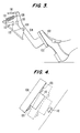
- the vehicle deceleration warning sensor 110 is mounted to the support arm 104 of the accelerator pedal.
- the sensor is mounted beyond the pivot point 106 on the rear end 108 of the support arm 104.
- a screw or pin having a base 112 and a contact head 113 is mounted on the floorboard of the vehicle such that when the gas pedal is released, VDWS 110 comes into contact with screw 112.
- the accelerator pedal remains unchanged, in particular it is mounted to the floorboard of a car by pivot 106, coupled to the carburetor cable 116 and returned biased by spring 114. It can be seen from Fig. 3 that during normal driving of the car, pedal 102 is depressed by the driver's foot 100 and the VDWS 110 is separated from screw 112.
- VDWS 110 comes into direct contact with screw 112 and mechanical force is applied to the piezoelectric crystal within VDWS 110.
- the brake lights will be activated only when the signal generated by the piezoelectric crystal is beyond a predetermined threshold value, in response to the change in the force or stress being applied by the contact with the screw 112 occurring within the predetermined time period. A signal above this threshold value will be generated when a greater force or stress is applied to the piezoelectric crystal quickly, in a small amount of time.
- Fig. 4 shows an enlarged view, the mounting of the VDWS 110 to the gas pedal according to the first mounting embodiment.
- VDWS 110 is mounted via mounting elements 120 to the rear end 108 of support arm 104.
- the movement of the VDWS 110 as the gas pedal is released is shown in dotted lines in Fig. 4.
- Fig. 5 illustrates the circuit diagram of the circuit contained on the printed circuit board of the VDWS 110.
- the circuit analyzes the signal obtained from the piezoelectric crystal 150 (labeled CR in Fig. 5) in order to determine when the predetermined threshold has been reached.
- the circuit also includes an anti-bouncing system that eliminates noise caused by vibrations of the vehicle.
- the VDWS circuit analyzes the characteristics ⁇ Force/ ⁇ Time of the mechanical input.
- the circuit is built to be tripped at a specific mechanical input threshold.
- the circuit consists of a power supply and regulator I, a piezoelectric sensor and analyzer II, a one shot timer section III and a power driver section IV.
- the input and output are either 0, 12 or 24 volts depending on the requirements of the particular vehicle including the type of battery used therein.
- the power supply I includes a transient voltage suppressor TZ, a reverse voltage safety diode D1, a filter R1, and a voltage regulator consisting of Zener diode D2 and capacitor C1.
- the piezoelectric sensor and analyzer II consists of the piezoelectric crystal CR, a piezoelectric protector resistor R2, a pull-down resistor R3, a Zener diode protector D3, a switching transistor TR and a pull-up resistor R4.
- the timer section III consists of a RC time constant including resistor R5 and capacitor C2 and a one-shot timer 502 consisting of a integrated circuit timing device.
- the power driver section IV consists of a power driver 504 which may be a solid state or relay device as required.
- the piezoelectric sensor and analyzer II will switch on the transistor TR as soon as the mechanical deformation of the piezoelectric crystal CR passes beyond a predetermined threshold value (R2+R3+D3) . That is, the transistor is switched on when the force of the mechanical deformation or stress occurs within a short enough time period to cause a signal to be generated by the crystal which is above the threshold value.
- the signal from transistor TR serves as input for the timer 502 which will switch on its' output for 1 second.
- the output of the timer 502 will activate a solid state driver or a power relay as required to turn on the brake lights. If the brake pedal is not pressed within the one second period, the lights will go out after one second. Otherwise, the lights will remain on in the normal way until the brake pedal is released.
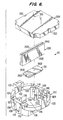
- a VDWS 110 according to an embodiment of the present invention is shown in an exploded view in Fig. 6.
- the shape of the housing can be changed according to the requirements of the installation.
- Housing 1102 forms a receptacle into which the sensor elements are inserted.
- Housing 1102 is formed of a material which is rigid but somewhat flexible, for example, plastic or stainless steel.
- plastic or stainless steel is the product sold under the trademark LEXAN® manufactured by General Electric Company.
- the material must be sufficiently flexible so that it is deformable in response to external pressure which is applied to activate the sensor. It also must be sufficiently flexible to allow such fitting of the various sensor elements within the housing. The material must also be sufficiently rigid so as to protect the piezoelectric crystal from damage.
- Housing 1102 includes a ring shaped support 1104 on which all other portions of the housing are attached.
- Support 1104 has a substantially circular shape, however, two portions thereof form flattened portions 1106.
- supports 1112 which form supports for bridge 1114.
- Four posts 1116 are attached to bridge 1114 on the inside of support 1104. Two of the posts 1116 are positioned adjacent to each flattened portion 1106 and are spaced from one another along the respective flattened portion. The amount of spacing is sufficient to allow an anisotropic conductive rubber element 1200 (described below) to be inserted therebetween.
- Groove 1118 is formed in the inside surface of bridge 1114.
- Posts 1120 extend from the opposite surface of support 1104 at positions 90° from flattened portions 1106.
- Posts 1120 include inwardly facing flanges 1122 which act to keep printed circuit board 1300 in place when the sensor is assembled.
- the printed circuit board 1300 snaps into place within the housing 1102. Cutouts 1302 on printed circuit board 1300 engage portions 1124 of posts 1120 when the sensor is assembled to assure correct positioning of the sensor elements within housing 1102.
- Piezoelectric crystal element 150 is fixed to the under-surface of bridge 1114 by an insulating adhesive 2440 (Fig. 7). Both the positive and the negative contacts, 2400 and 2420, respectively, are located on the side of the crystal which is not fixed to bridge 1114. A gap 2430 is formed between poles 2400 and 2420. In this way, by providing both contacts on one side, the crystal is easily electrically connected to the remainder of the circuit elements. The polarity of the poles is interchangeable.
- the piezoelectric crystal element 150 can be made from a standard ceramic material.
- PPK21 is used, manufactured by Stettner & Co. of Lauf, Federal Republic of Germany.
- the piezoelectric crystal exhibits a high coupling factor, high permittivity, high piezoelectric strain constant and broadband behavior through low mechanical Q-factor. Additionally, as mentioned above, the crystal has the inherent characteristic that an increasingly high level electrical signal is generated as the force per unit time exerted on the crystal increases.
- the anisotropic conductive elastomeric connector 1200 is disposed so as to have one longitudinal edge extend across the longitudinal exposed face of the piezoelectric element 150.
- the connector 1200 is inserted into the housing 1102 in the space formed between posts 1116.
- the connector is held within the housing by the printed circuit 1300 when the board is snapped into place.
- Connector 1200 may be any anisotropic conductive elastomeric material but is preferably a Series 1000/2000 ZEBRA® connector manufactured by Tecknit Co., of Cranford, N.J.
- Such a connector is formed as a sandwich, in which a conductive portion 2640 is layered between two insulating layers 2620.
- Conductive portion 2640 is constructed of strips of insulating material 2660 alternating with strips of conductive material 2680, shown in Fig. 7.
- the positive pole 2400 of the piezoelectric ceramic is linked electrically through the conductive portions 2680 of connector 1200 to contact 2840 of printed circuit board 1300.
- Negative pole 2420 is linked electrically to contact 2820.
- the anisotropicity caused by the alternating conductive and insulating strips 2680, 2660 permits electrical connection of the respective contacts without short-circuiting of contacts of opposite polarity.
- elastomeric connector facilitates the snap fitting of the component into the housing 1102 and protects the piezoelectric crystal 150 from physical shock which may come from the direction of the open side of the housing 1102. Furthermore, the combination of the elastomeric connector with the piezoelectric crystal having both poles on one side allows all electrical connections between the crystal and the printed circuit board to be solder-free.
- Contacts 300 on circuit board 1300 are used to connect the circuit to the outside world.
- the contacts may be in any form according to the requirements of the mounting system used to mount the sensor on the accelerator pedal.
- Figs. 8A-8E illustrate five embodiments which can be used to mount the VDWS on the accelerator pedal.
- Fig. 8A illustrates substantially the embodiment described above with respect to Figs. 3 and 4 where the sensor element 110 and the base 112 and the contact head 113 are located beyond the pivot point.
- the sensor element 110 is disposed on the floorboard and the contact pin base 112 is on the support arm of the pedal.
- Fig. 8B illustrates an embodiment in which the VDWS is mounted beyond the pivot point of the accelerator pedal and the contact element 112′ is pivotally mounted to the sensor element 110′.
- the contact element 112′ includes a contact arm 113′ that reaches over the sensor element 110′ and is biased by a spring 115′ towards the pedal support arm.
- the force of the pedal support arm overcomes the bias force of spring 115′ thus compressing the spring, causing a greater level of stress or force on the sensor element 110′ and thus on the piezoelectric crystal housed therein.
- the piezoelectric crystal is made with both the positive and negative poles on one side of the crystal.
- positive pole 2400 covers a substantial portion of the crystal face while negative pole 2420 occupies a smaller portion of the crystal face.
- Figs. 8C, 8D and 8E all make use of this principle.
- the VDWS is disposed in front of the pivot point of the accelerator.
- the contact head 113 in Fig. 8C is in contact with the housing of the VDWS, and thereby the crystal.
- spring 115′ itself actually is in contact with the housing and is depressed by contact element arm 113′ causing increased and decreased amounts of stress on the crystal.
- the sensor element 110'' is mounted within the accelerator pedal.
- a contact arm 113'' is pivotally mounted to the pedal above the VDWS.
- Contact arm 113'' presses on a spring 115'', either a coil or a leaf spring, which is in contact with the housing, and thus with the piezoelectric crystal.
- the springs 115, 115′ and 115'' allow contact with the crystal even when the pedal is not fully depressed.
- Figs 9A and 9B illustrate the connection between the VDWS and the brake lights. The two embodiments are shown because different vehicles require different connections.
- the output of the VDWS is connected to the switch 90 which controls the brake lights in response to brake pedal actuation.
- one terminal of the switch 90 is connected to the battery, the other terminal is connected to brake lights 92 and brake lights 92 are connected to ground. In this case, the output of the VDWS will either be 12 or 24 volts, depending on the type of battery used.
- Fig. 9B one terminal of the switch 90 is connected to ground, the other terminal is connected to brake lights 92 and brake lights 92 are connected to the battery. In this case, the output of the VDWS will be 0 volts.
- switch 90 is closed either by the VDWS or by normal actuation of the brake pedal.
- the material used to construct the housing may be changed from plastic to for example, metal, or any other suitable material.
- the VDWS is a self-contained element which has no moving parts, is easy to assemble and is easily attached to the gas pedal in the vehicle in which is to be used.
- the VDWS may be connected by the automobile manufacturer at the time of manufacture or may be installed later by the dealer or by the purchaser.
Landscapes
- Engineering & Computer Science (AREA)
- Mechanical Engineering (AREA)
- Lighting Device Outwards From Vehicle And Optical Signal (AREA)
- Burglar Alarm Systems (AREA)
- Vehicle Body Suspensions (AREA)
- Regulating Braking Force (AREA)
- Braking Elements And Transmission Devices (AREA)
Abstract
Description
- The present invention relates to a vehicle deceleration warning apparatus which would provide early warning of an impending stop by advance brake light activation, prior to actuation of the brake pedals.
- Rear-end automobile collisions account for approximately two-thirds of the auto accidents occurring worldwide. The majority of all chain accidents occur during rush-hour traffic jams. Under those conditions, drivers often do not have enough time to react to one anothers movements. As it appears to be impossible to force drivers to maintain safe distances between cars, other solutions must be found.
- One recently implemented solution is the center-high-mounted-stop lamp (CHMSL) introduced in the United States in the early 1980's. Pursuant to Federal regulation 49 CFR 571.108 (Standard 108) the installation of this device in all new cars became a mandatory requirement. The CHMSL provides significant advantages and benefits in preventing some rear-end collisions.
- However, rear-end collisions are still occurring at an alarming rate. Other devices have been developed which are directed to the prevention of rear-end collisions and their severity by advancing the reaction-braking response in emergency braking situations; this in contrast to the CHMSL method which reduces driver's reaction time in emergency-braking situations.
- The following US-patents disclose various types of early warning systems.
Patent No. Inventor 3,171,914 Ohanian 3,171,917 Leichsenring 3,395,388 Hendrickson 3,497,871 Damico 3,596,020 Warren 3,601,796 Mortimer 3,881,078 Kazanecki 3,911,394 Shames 3,912,892 Morehouse 3,921,750 Shames 4,021,775 Leu 4,173,012 Burger 4,686,503 Miller - Mortimer discloses an accelerator release signal light delay actuator which delays actuation of the brake light upon release of the driver's foot from the accelerator pedal for 5 or 6 seconds following release of the accelerator. After the delay period is past, if the brake has not yet been applied, the brake lights are turned on at an intensity less than the intensity available when the brakes are actually actuated. Thus, the possibility of false indication is decreased since the person behind the front car recognizes the decreased intensity of the light indicating that the brake has not itself been actuated.
- Morehouse discloses an automobile deceleration warning system in which an auxiliary pedal is positioned above the main accelerator pedal. A normally opened switch is positioned between the two pedals. Upon release of the auxiliary pedal, the switch closes, thereby lighting the brake light. According to the patent, a resistor may be included which reduces the current flow to the brake lights, thus lighting the brake lights at a lower intensity when the lights are actuated in response to the lifting of the accelerator pedal as compared with the intensity of the brake lights when the brakes are actually applied.
- The Shames patents disclose a vehicle brake light warning system in which the brake lights are activated for a given period of time upon release of the accelerator pedal. This time period is sufficient for the driver to lift his foot from the accelerator to the brake pedal. If the brakes are not applied within that time period, the brake lights are turned off.
- Burger, Leu, Kazanecki, Warren, Ohanian and Miller all disclose alternate systems for providing early warning of brake activation by turning on the brake light or alternative lights upon release of the accelerator pedal.
- However, all of the above noted patents suffer from a significant disadvantage in that no differentiation is made between panic stop behavior and non-panic stop behavior. Each of these devices result in a high rate of "false alarms" which can lead to a decrease in the overall warning value of the stop lamp signal itself, due to a "cry wolf" phenomenon. This leads to a significant reduction in the effectiveness of these systems.
- European Patent No. 0 219 858 discloses a device which remains ineffective in non-emergency cases. The advanced braking light device (ABLD) is an electronic device installed on a vehicle accelerator pedal. When a leading vehicle driver attempts a panic-braking operation, the accelerator pedal is released by a sudden movement when the driver's leg is shifted to apply the brake pedal as quickly as possible.
- The sudden release is sensed by the ABLD and immediately after the accelerator pedal is released, the stop lights are activated. This advanced activation of the stop lights, by a fraction of 0.2-0.3 seconds, which is approximately the time necessary for the driver to move his leg from the accelerator to the brake, enables the following vehicle driver to start his reaction to the braking at an earlier stage, thus improving his chances of preventing a collision or reducing the severity thereof. The brake lights remain lit for only 1 second if the brake pedal is not actuated.
- The ABLD
device 10 is shown in Figs. 1 and 2 of the present application. When thebellows 14 is in its collapsed position, i.e., the drivers foot is on the pedal, electrical contacts 38 and 41 are separated and the circuit is opened. Upon sudden release of the accelerator pedal, theswitching device 40 closes andbellows 14 becomes momentarily effective to generate sub-pressure inside, thereby causing an air suction effect through the opening. This forces theflap 54 to lift and make electrical contact with the rim 22, and short-circuit theterminals coil spring 26. By actuation of therelay 62, thebrake lights 70 are turned on. - A moderate movement will not effect actuation of the brake lights since air will gradually refill the chamber within
bellows 14 without causing an air-lift or suction phenomena of the required amount to overcome thecoil spring force 26. The patent also discloses an electrical version of the device which does not include thebellows 14. A potentiometer is provided so as to avoid brake light activation based on slower movements of the driver's foot wherein movements below as certain speed will have no effect on the system. - The ABLD of the European patent application is bulky, complicated and expensive to manufacture. In addition, because of the number of moving parts and the provision of a flexible rubber bellows, this device is likely to wear out and break frequently thus reducing its cost effectiveness.
- Patents have been issued which disclose the use of a vehicle pedal operated switch mounted on an upper end portion of the arm connected to the foot pedal (see U.S. Patent Nos. 3,763,975, 3,846,599, and 4,333,070). It has been known to use piezoelectric crystals in key switches which form a keyboard (see U.S. Patent No. 4,737,767).
- It is an object of the present invention to provide a vehicle deceleration warning apparatus which overcomes the disadvantages noted above with respect to the prior art systems.
- It is a further object of the present invention to provide a vehicle deceleration warning apparatus which has no moving parts and is simple and inexpensive to manufacture and repair.
- It is a further object of the invention to provide a vehicle deceleration warning apparatus which is activated only upon emergency or panic braking conditions and not under normal driving circumstances.
- It is a further object of the present invention to provide an apparatus which effectively decreases to a minimum the time between the moment a driver notices danger ahead and releases the accelerator pedal and the moment the brake lights are activated in emergency conditions.
- It is a further object of the present invention to provide an apparatus attachable to the accelerator pedal of automobiles which will be instantaneously responsive to the abrupt or sudden release of the accelerator pedal, and activate the brake lights before activation thereof by the brake pedal.
- The inventor of this application recognized that all piezoelectric crystals, such as those used in US-A-4,737,767, have an inherent characteristic whereby the electrical signal generated by the piezoelectric crystal increases in magnitude as the force per unit time exerted on the crystal increases. Thus, the output of a piezoelectric crystal would be greater when a certain amount of force is exerted on the crystal in a given amount of time than when the same amount of force is exerted in a greater period of time. The present invention was designed to make use of this inherent characteristic to create a vehicle deceleration warning apparatus which actuated the brake lights only in emergency situations.
- According to the present invention, a vehicle deceleration warning apparatus is provided for use in a vehicle having brake lights, a floorboard and an accelerator pedal which comprises, piezoelectric sensor means connected to one of the accelerator pedal or the floorboard for outputting a first signal when subjected to appropriate stress conditions, contact means connected to the other of the accelerator pedal or the floorboard for contacting the piezoelectric sensor means in a manner which is dependent upon the rate of release of the accelerator pedal and causing the sensor means to output the first signal in response thereto, and circuit means connected to the brake lights and to the piezoelectric sensor means for analyzing the first signal produced by the piezoelectric sensor means and for actuating the brake lights in response to the analysis when the first signal is above a predetermined threshold.
- The apparatus according to the present invention further comprises a housing. The piezoelectric sensor means comprises a piezoelectric crystal which is contained within the housing and connected to the housing such that contact with the housing causes a mechanical deformation of the crystal. The crystal is also connected to an input of the circuit means and the input is adapted to receive the first signal.
- Still other objects, features and attendant advantages of the present invention will become apparent to those skilled in the art from a reading of the following detailed description of the embodiments constructed in accordance therewith, taken in conjunction with the accompanying drawings.
- The invention of the present application will now be described in more detail with reference to the preferred embodiments of the device, given only by way of example, and with reference to the accompanying drawings, in which:
- Fig. 1 illustrates the mounting of the ABLD on the accelerator pedal of a vehicle;
- Fig. 2 is a schematic, cross-sectional view of the advanced brake light device in the prior art;
- Fig. 3 illustrates the mounting of the vehicle deceleration warning sensor of the present invention on the accelerator pedal according to a first embodiment;
- Fig. 4 is a exploded view of the VDWS according to the first embodiment of the present invention as it is actuated by movement of the gas pedal;
- Fig. 5 is a circuit diagram contained on the printed circuit board according to the present invention;
- Fig. 6 illustrates an exploded view of a piezoelectric sensor according to a preferred embodiment of the present invention;
- Fig. 7 is a cross-sectional view of the elements of the sensor according to the present invention;
- FIG. 8A, 8B, 8C, 8D, and 8E illustrate various embodiments for mounting the vehicle deceleration warning apparatus according to the present invention; and
- Figs. 9A and 9B illustrate two examples of the connection of the VDWS according to the present invention to the brake lights.
- As schematically shown in Fig. 3, according to a first mounting embodiment the vehicle deceleration warning sensor 110 (VDWS) is mounted to the
support arm 104 of the accelerator pedal. The sensor is mounted beyond thepivot point 106 on therear end 108 of thesupport arm 104. A screw or pin having a base 112 and acontact head 113 is mounted on the floorboard of the vehicle such that when the gas pedal is released,VDWS 110 comes into contact withscrew 112. In all other respects, the accelerator pedal remains unchanged, in particular it is mounted to the floorboard of a car bypivot 106, coupled to thecarburetor cable 116 and returned biased byspring 114. It can be seen from Fig. 3 that during normal driving of the car,pedal 102 is depressed by the driver'sfoot 100 and theVDWS 110 is separated fromscrew 112. - If the driver abruptly or suddenly releases his foot from the
head portion 102 of the gas pedal,VDWS 110 comes into direct contact withscrew 112 and mechanical force is applied to the piezoelectric crystal withinVDWS 110. The brake lights will be activated only when the signal generated by the piezoelectric crystal is beyond a predetermined threshold value, in response to the change in the force or stress being applied by the contact with thescrew 112 occurring within the predetermined time period. A signal above this threshold value will be generated when a greater force or stress is applied to the piezoelectric crystal quickly, in a small amount of time. - Due to the aforementioned inherent characteristics of piezoelectric crystals, a moderate or slow movement of the driver's
foot 100 to release thehead portion 102 of the gas pedal will not cause brake light activation. Because the increase in the force applied to the piezoelectric crystal must occur within a given amount of time to generate a signal having the predetermined threshold level, slow release of the pedal, which causes slow contact between the crystal and screw 112, will not actuate the brake lights. - Fig. 4 shows an enlarged view, the mounting of the
VDWS 110 to the gas pedal according to the first mounting embodiment.VDWS 110 is mounted via mountingelements 120 to therear end 108 ofsupport arm 104. The movement of theVDWS 110 as the gas pedal is released is shown in dotted lines in Fig. 4. - Fig. 5 illustrates the circuit diagram of the circuit contained on the printed circuit board of the
VDWS 110. The circuit analyzes the signal obtained from the piezoelectric crystal 150 (labeled CR in Fig. 5) in order to determine when the predetermined threshold has been reached. The circuit also includes an anti-bouncing system that eliminates noise caused by vibrations of the vehicle. The VDWS circuit analyzes the characteristics ΔForce/Δ Time of the mechanical input. The circuit is built to be tripped at a specific mechanical input threshold. - As outlined in dotted lines in Fig. 5, the circuit consists of a power supply and regulator I, a piezoelectric sensor and analyzer II, a one shot timer section III and a power driver section IV. The input and output are either 0, 12 or 24 volts depending on the requirements of the particular vehicle including the type of battery used therein.
- The power supply I includes a transient voltage suppressor TZ, a reverse voltage safety diode D1, a filter R1, and a voltage regulator consisting of Zener diode D2 and capacitor C1. The piezoelectric sensor and analyzer II consists of the piezoelectric crystal CR, a piezoelectric protector resistor R2, a pull-down resistor R3, a Zener diode protector D3, a switching transistor TR and a pull-up resistor R4. The timer section III consists of a RC time constant including resistor R5 and capacitor C2 and a one-
shot timer 502 consisting of a integrated circuit timing device. The power driver section IV consists of apower driver 504 which may be a solid state or relay device as required. - The piezoelectric sensor and analyzer II will switch on the transistor TR as soon as the mechanical deformation of the piezoelectric crystal CR passes beyond a predetermined threshold value

timer 502 which will switch on its' output for 1 second. The output of thetimer 502 will activate a solid state driver or a power relay as required to turn on the brake lights. If the brake pedal is not pressed within the one second period, the lights will go out after one second. Otherwise, the lights will remain on in the normal way until the brake pedal is released. - A
VDWS 110 according to an embodiment of the present invention is shown in an exploded view in Fig. 6. Of course, it it understood that the shape of the housing can be changed according to the requirements of the installation. -
Housing 1102 forms a receptacle into which the sensor elements are inserted.Housing 1102 is formed of a material which is rigid but somewhat flexible, for example, plastic or stainless steel. One example of such a plastic material is the product sold under the trademark LEXAN® manufactured by General Electric Company. - The material must be sufficiently flexible so that it is deformable in response to external pressure which is applied to activate the sensor. It also must be sufficiently flexible to allow such fitting of the various sensor elements within the housing. The material must also be sufficiently rigid so as to protect the piezoelectric crystal from damage.
-
Housing 1102 includes a ring shapedsupport 1104 on which all other portions of the housing are attached.Support 1104 has a substantially circular shape, however, two portions thereof form flattenedportions 1106. Descending from one surface ofsupport 1104, atportions 1106, are twoclips 1108 which can be used to removably secure the sensor to a mounting element for attachment to the gas pedal. Theseclips 1108 are squeezed toward one another during insertion and, when in place,flange 1110 acts to secure the sensor to the mounting element (not shown). - Also descending from
support 1104 at approximately the position of the flattenedportions 1106 aresupports 1112 which form supports forbridge 1114. Fourposts 1116 are attached to bridge 1114 on the inside ofsupport 1104. Two of theposts 1116 are positioned adjacent to each flattenedportion 1106 and are spaced from one another along the respective flattened portion. The amount of spacing is sufficient to allow an anisotropic conductive rubber element 1200 (described below) to be inserted therebetween.Groove 1118 is formed in the inside surface ofbridge 1114. -
Posts 1120 extend from the opposite surface ofsupport 1104 atpositions 90° from flattenedportions 1106.Posts 1120 include inwardly facingflanges 1122 which act to keep printedcircuit board 1300 in place when the sensor is assembled. The printedcircuit board 1300 snaps into place within thehousing 1102. Cutouts 1302 on printedcircuit board 1300 engageportions 1124 ofposts 1120 when the sensor is assembled to assure correct positioning of the sensor elements withinhousing 1102. -
Piezoelectric crystal element 150 is fixed to the under-surface ofbridge 1114 by an insulating adhesive 2440 (Fig. 7). Both the positive and the negative contacts, 2400 and 2420, respectively, are located on the side of the crystal which is not fixed to bridge 1114. Agap 2430 is formed betweenpoles - The
piezoelectric crystal element 150 can be made from a standard ceramic material. In the preferred embodiment, PPK21 is used, manufactured by Stettner & Co. of Lauf, Federal Republic of Germany. The piezoelectric crystal exhibits a high coupling factor, high permittivity, high piezoelectric strain constant and broadband behavior through low mechanical Q-factor. Additionally, as mentioned above, the crystal has the inherent characteristic that an increasingly high level electrical signal is generated as the force per unit time exerted on the crystal increases. - The anisotropic conductive
elastomeric connector 1200 is disposed so as to have one longitudinal edge extend across the longitudinal exposed face of thepiezoelectric element 150. Theconnector 1200 is inserted into thehousing 1102 in the space formed betweenposts 1116. The connector is held within the housing by the printedcircuit 1300 when the board is snapped into place.Connector 1200 may be any anisotropic conductive elastomeric material but is preferably a Series 1000/2000 ZEBRA® connector manufactured by Tecknit Co., of Cranford, N.J. Such a connector is formed as a sandwich, in which aconductive portion 2640 is layered between two insulatinglayers 2620.Conductive portion 2640 is constructed of strips of insulatingmaterial 2660 alternating with strips ofconductive material 2680, shown in Fig. 7. - In this particular case, the
positive pole 2400 of the piezoelectric ceramic is linked electrically through theconductive portions 2680 ofconnector 1200 to contact 2840 of printedcircuit board 1300.Negative pole 2420 is linked electrically to contact 2820. The anisotropicity caused by the alternating conductive and insulatingstrips - The use of such an elastomeric connector facilitates the snap fitting of the component into the
housing 1102 and protects thepiezoelectric crystal 150 from physical shock which may come from the direction of the open side of thehousing 1102. Furthermore, the combination of the elastomeric connector with the piezoelectric crystal having both poles on one side allows all electrical connections between the crystal and the printed circuit board to be solder-free. -
Contacts 300 oncircuit board 1300 are used to connect the circuit to the outside world. The contacts may be in any form according to the requirements of the mounting system used to mount the sensor on the accelerator pedal. - It is understood that the shape of
housing 1102 which houses thepiezoelectric crystal 150 may be changed to fit the needs of the particular mounting system used. Figs. 8A-8E illustrate five embodiments which can be used to mount the VDWS on the accelerator pedal. Fig. 8A illustrates substantially the embodiment described above with respect to Figs. 3 and 4 where thesensor element 110 and thebase 112 and thecontact head 113 are located beyond the pivot point. Of course as shown in Fig. 8A, thesensor element 110 is disposed on the floorboard and thecontact pin base 112 is on the support arm of the pedal. - Fig. 8B illustrates an embodiment in which the VDWS is mounted beyond the pivot point of the accelerator pedal and the
contact element 112′ is pivotally mounted to thesensor element 110′. Thecontact element 112′ includes acontact arm 113′ that reaches over thesensor element 110′ and is biased by aspring 115′ towards the pedal support arm. In Fig. 8B, when the pedal is released, the force of the pedal support arm overcomes the bias force ofspring 115′ thus compressing the spring, causing a greater level of stress or force on thesensor element 110′ and thus on the piezoelectric crystal housed therein. - As noted above with respect to Figs. 6 and 7, the piezoelectric crystal is made with both the positive and negative poles on one side of the crystal. As shown in Fig. 6,
positive pole 2400 covers a substantial portion of the crystal face whilenegative pole 2420 occupies a smaller portion of the crystal face. Using this configuration, when the crystal is struck quickly, causing an increased amount of stress thereon, a signal is generated which exceeds a predetermined threshold level. The present inventor has discovered that if the polarity of the piezoelectric crystal is reversed, an opposite effect is achieved. That is, if contact with the crystal is maintained, and then released suddenly, causing a decreased amount of stress on the crystal, a signal is generated by the crystal above the predetermined threshold. - The embodiments shown in Figs. 8C, 8D and 8E all make use of this principle. In Figs. 8C and 8D the VDWS is disposed in front of the pivot point of the accelerator. In this way, when the pedal is depressed, the
contact head 113 in Fig. 8C is in contact with the housing of the VDWS, and thereby the crystal. In Fig. 8D,spring 115′ itself actually is in contact with the housing and is depressed bycontact element arm 113′ causing increased and decreased amounts of stress on the crystal. In Fig. 8E, the sensor element 110'' is mounted within the accelerator pedal. A contact arm 113'' is pivotally mounted to the pedal above the VDWS. Contact arm 113'' presses on a spring 115'', either a coil or a leaf spring, which is in contact with the housing, and thus with the piezoelectric crystal. Thesprings - When the pedal is quickly released, a signal is generated by the piezoelectric crystal which is above the predetermined threshold level. This signal is analyzed by the circuit described in Fig. 5.
- Figs 9A and 9B illustrate the connection between the VDWS and the brake lights. The two embodiments are shown because different vehicles require different connections.
- In both embodiments, the output of the VDWS is connected to the
switch 90 which controls the brake lights in response to brake pedal actuation. In Fig. 9A, one terminal of theswitch 90 is connected to the battery, the other terminal is connected tobrake lights 92 andbrake lights 92 are connected to ground. In this case, the output of the VDWS will either be 12 or 24 volts, depending on the type of battery used. In Fig. 9B, one terminal of theswitch 90 is connected to ground, the other terminal is connected tobrake lights 92 andbrake lights 92 are connected to the battery. In this case, the output of the VDWS will be 0 volts. Thus, switch 90 is closed either by the VDWS or by normal actuation of the brake pedal. - It is understood that the material used to construct the housing may be changed from plastic to for example, metal, or any other suitable material.
- The VDWS is a self-contained element which has no moving parts, is easy to assemble and is easily attached to the gas pedal in the vehicle in which is to be used. The VDWS may be connected by the automobile manufacturer at the time of manufacture or may be installed later by the dealer or by the purchaser.
Claims (9)
- A vehicle deceleration warning apparatus for use in a vehicle having brake lights, a floorboard and an accelerator pedal, characterized by
piezoelectric sensor means (VDWS 110) connected to one of the accelerator pedal or the floorboard for outputting a first signal when subjected to an appropriate stress condition;
contact means (112,112',113,113',113'') connected to the other of the accelerator pedal or the floorboard for contacting said piezoelectric sensor means (VDWS 110) upon release of the accelerator pedal and causing said sensor means (VDWS 110) to output said first signal in response to the change of stress being applied by the contact means (112,112',113,113',113'') to the piezoelectric sensor means (VDWS 110); and
circuit means (I,II,III,IV) connected to the brake lights and to said piezoelectric sensor means (VDWS 110) for analyzing said first signal produced by said piezoelectric sensor means (VDWS 110) and for actuating the brake lights in response to the analysis when said first signal is above a predetermined threshold. - The apparatus according to claim 1, further comprising a housing (1102), wherein said piezoelectric sensor means (VDWS 110) comprises a piezoelectric crystal (150), said crystal (150) being contained within said housing (1102) and connected to said housing (1102) such that contact with said housing (1102) causes said crystal (150) to be subjected to a stress condition, said crystal (150) being also connected to an input (2840) of said circuit means, (I,II,III,IV) the input (2840) being adapted to receive said first signal.
- The apparatus according to claim 2, wherein said circuit means comprises:
signal generating means (II) connected to said piezoelectric crystal (CR) for generating a second signal when said first signal is above a predetermined threshold;
a transistor (TR) for receiving said second signal, said transistor (TR) being switched to an on state in response to said second signal;
timer means (502) having an output which is switched on for a predetermined time period in response to the on state of the transistor (TR); and
driver means (504) connected between said timer means (502) and the brake lights for turning on the brake lights at least for the predetermined time period in response to the output of said timer means (502). - The apparatus according to claim 2, wherein said contact means comprises:
a base (112) connected to a portion of an accelerator pedal support arm beyond a pivot point on the support arm with respect to a head portion of the pedal; and
a contact head (113) connected to said base (112),
wherein said housing (1102) is disposed on the floorboard at a position corresponding to the position of the base (112) on the support arm, and whereby said contact head (113) is separated from said housing (1102) when the accelerator pedal is depressed and is brought towards contact with said housing (1102) when the accelerator pedal is released thus causing the crystal (150) to be subjected to a stress condition by the contact head (113), wherein the stress condition applied to the crystal (150) is the appropriate stress condition when the rate of release of the pedal is faster than a particular rate. - The apparatus according to claim 2, wherein said contact means comprises:
a contact arm (113') having a pivot end pivotally connected to said housing (1102) and a free end;
spring means (115') connected between said housing (1102) and said free end,
wherein said housing (1102) is disposed on the floorboard at a position corresponding to a portion of an accelerator pedal support arm beyond a pivot point on the support arm with respect to a head portion of the pedal, and whereby said contact arm free end is separated from said housing (1102) when the accelerator pedal is depressed and is brought towards contact with said housing (1102) when the accelerator pedal is released causing the crystal (150) to be subjected to a stress condition by the spring means (115'), wherein the stress condition applied to the crystal (150) is the appropriate stress condition, when the rate of release of the pedal is faster then a particular rate. - The apparatus according to claim 2, wherein said contact means comprises:
a base (112) connected to a portion of an accelerator pedal support arm between a pivot point on the support arm and a head portion of the pedal; and
spring means (115) having one end connected to said base (112);
a contact head (113) connected to a second end of said spring means (115), and
wherein said housing (1102) is disposed on the floorboard at a position corresponding to the position of the base (112) on the support arm, and whereby said contact head (113) is brought towards contact with said housing (1102) when the accelerator pedal is depressed and is separated from said housing (1102) when the accelerator pedal is released causing the crystal (150) to be subjected to a stress condition by the contact head (113) wherein the stress condition applied to the crystal (150) is the appropriate stress condition when the rate of release of the pedal is faster than a particular rate. - The apparatus according to claim 2, wherein said contact means comprises:
a contact arm (113') having a pivot end pivotally connected to said housing (1102) and a free end;
spring means (115') connected between said housing (1102) and said free end,
wherein said housing (1102) is disposed on the floorboard at a position corresponding to a portion of an accelerator pedal support arm between a pivot point on the support arm and a head portion of the pedal, and whereby said contact arm (113') is brought towards contact with said housing (1102) when the accelerator pedal is depressed and is separated from said housing (1102) when the accelerator pedal is released causing the crystal (150) to be subjected to a stress condition by the spring means (115'), wherein the stress condition applied to the crystal (150) is the appropriate stress condition when the rate of release of the pedal is faster than a particular rate. - The apparatus according to claim 2, wherein the accelerator pedal comprises a head portion, said housing (1102) being disposed within said head portion, and wherein said contact means comprises:
a contact arm (113'') pivotally connected to said accelerator pedal head portion and adapted to receive a driver's foot;
spring means (115'') connected between said contact arm (113'') and said head portion,
wherein said contact element (113'') is brought towards contact with said housing (1102) when the accelerator pedal is depressed and is separated from said housing (1102) when the accelerator pedal is released causing the crystal (150) to be subjected to a stress condition by the spring means, wherein the stress condition applied to the crystal is the appropriate stress condition when the rate of release of the pedal is faster than a particular rate. - The apparatus according to claim 2, wherein said contact means comprises:
a base (112') connected to the floorboard beyond a pivot point of an accelerator pedal support arm with respect to the pedal; and
a contact head (113') connected to said base,
wherein said housing (1102) is disposed on a portion of the accelerator pedal support arm at a position corresponding to the position of the base (112') on the floorboard, and whereby said contact head (113') is separated from said housing (1102) when the accelerator pedal is depressed and is brought towards contact with said housing (1102) when the accelerator pedal is released causing the crystal (150) to be subjected to a stress condition by the spring means (115'), wherein the stress condition applied to the crystal (150) is the appropriate stress condition when the rate of release of the pedal is faster than a particular rate.
Priority Applications (1)
| Application Number | Priority Date | Filing Date | Title |
|---|---|---|---|
| AT8989117096T ATE104614T1 (en) | 1988-09-20 | 1989-09-15 | WARNING DELAY PIEZO SENSOR FOR VEHICLES. |
Applications Claiming Priority (2)
| Application Number | Priority Date | Filing Date | Title |
|---|---|---|---|
| US246687 | 1988-09-20 | ||
| US07/246,687 US4901055A (en) | 1988-09-20 | 1988-09-20 | Vehicle deceleration warning piezo-sensor |
Publications (3)
| Publication Number | Publication Date |
|---|---|
| EP0360167A2 EP0360167A2 (en) | 1990-03-28 |
| EP0360167A3 EP0360167A3 (en) | 1990-08-16 |
| EP0360167B1 true EP0360167B1 (en) | 1994-04-20 |
Family
ID=22931779
Family Applications (1)
| Application Number | Title | Priority Date | Filing Date |
|---|---|---|---|
| EP89117096A Expired - Lifetime EP0360167B1 (en) | 1988-09-20 | 1989-09-15 | Vehicle deceleration warning piezo-sensor |
Country Status (6)
| Country | Link |
|---|---|
| US (1) | US4901055A (en) |
| EP (1) | EP0360167B1 (en) |
| JP (1) | JPH0667705B2 (en) |
| AT (1) | ATE104614T1 (en) |
| DE (1) | DE68914759T2 (en) |
| ES (1) | ES2051336T3 (en) |
Families Citing this family (33)
| Publication number | Priority date | Publication date | Assignee | Title |
|---|---|---|---|---|
| DE4022856A1 (en) * | 1990-07-18 | 1990-12-06 | Eugen Ringwald | Automatic brake light switch of motor vehicle - includes contact at acceleration pedal to give early warning to following drivers when foot is taken from pedal |
| EP0501555B1 (en) * | 1991-03-01 | 1997-12-17 | Baran Advanced Technologies (86) Ltd | Brake lights activation system and inertial signal-generating device therefor |
| US5210522A (en) * | 1991-10-09 | 1993-05-11 | Hoekman Robert J | Early warning brake light actuated by the accelerator pedal |
| NZ245165A (en) * | 1992-11-18 | 1997-07-27 | Geoffrey Miles Furness | Imminent braking warning monitors drop in pressure on vehicle accelerator pedal |
| DE4336917A1 (en) * | 1993-10-29 | 1995-05-04 | Alexander Oberhof | Method and system for warning road users of the braking of a vehicle |
| US5835008A (en) * | 1995-11-28 | 1998-11-10 | Colemere, Jr.; Dale M. | Driver, vehicle and traffic information system |
| CN2309249Y (en) * | 1997-08-27 | 1999-03-03 | 杨士朋 | Advanced warning device for rear-end collision prevention brake lamp of motor vehicle |
| US6002349A (en) * | 1998-08-14 | 1999-12-14 | Safe Flight Instrument Corporation | Helicopter anti-torque limit warning device |
| DE60002551T2 (en) * | 2000-02-19 | 2004-06-09 | Robert Bosch Gmbh | Method and device for detecting a brake switch fault |
| US6919801B2 (en) * | 2003-10-06 | 2005-07-19 | Jae Yeal Kim | Vehicle safety system for preventing inadvertent acceleration of a vehicle |
| US20060087176A1 (en) * | 2003-12-01 | 2006-04-27 | Henri Duong | Back driving automatic brake system & automatic braking system for equipping in all vehicles, airplanes, ships etc.. |
| US7077549B1 (en) | 2004-02-04 | 2006-07-18 | Corliss Joseph J | Vehicle warning light system |
| US7499785B2 (en) * | 2004-10-22 | 2009-03-03 | Delphi Technologies, Inc. | Extended braking compensation in hybrid braking systems |
| US20060125617A1 (en) * | 2004-12-13 | 2006-06-15 | Benjamin Zimmermann | Method and apparatus for anticipated brake light activation |
| WO2006107301A1 (en) * | 2005-04-05 | 2006-10-12 | Jae Yeal Kim | Vehicle safety system for preventing inadvertent acceleration of a vehicle |
| US20070008095A1 (en) * | 2005-06-09 | 2007-01-11 | Gwinn H S M | Intelligent brake light system |
| KR101129794B1 (en) * | 2006-12-15 | 2012-03-23 | 현대중공업 주식회사 | Automatic stop lamp control system using accelerator pedal |
| US20090091440A1 (en) * | 2007-10-09 | 2009-04-09 | Roman Kendyl A | Brake light with pre-brake warning |
| TWM348712U (en) * | 2008-04-02 | 2009-01-11 | Cycle Technology Company Ltd | Pre-brake deceleration warning device for vehicle |
| DE102010054050A1 (en) * | 2010-12-10 | 2012-06-14 | Knorr-Bremse Systeme für Nutzfahrzeuge GmbH | Circuit board assembly with a microswitch clamped between a printed circuit board and a printed circuit board carrier |
| US9371001B2 (en) | 2012-04-20 | 2016-06-21 | The Trustees Of Dartmouth College | Sudden acceleration shutdown device using hydraulic brake pressure detector to disable vehicle on driver panic |
| JP5990415B2 (en) * | 2012-07-02 | 2016-09-14 | Kyb株式会社 | Brake operation detection device |
| WO2014152802A1 (en) * | 2013-03-14 | 2014-09-25 | Gerald Murphy | Driver control assistance sensor and method |
| ITTO20130307A1 (en) | 2013-04-17 | 2014-10-18 | Itt Italia Srl | METHOD TO REALIZE A BRAKE ELEMENT, IN PARTICULAR A BRAKE PAD, SENSORIZED, SENSORED BRAKE PAD, VEHICLE BRAKE SYSTEM AND ASSOCIATED METHOD |
| ES2539876B1 (en) | 2013-06-10 | 2016-02-24 | Juan José PINO MÉNDEZ | Device for the prevention of accidents due to rear-end collision and its operating system |
| US9939035B2 (en) | 2015-05-28 | 2018-04-10 | Itt Italia S.R.L. | Smart braking devices, systems, and methods |
| ITUB20153709A1 (en) | 2015-09-17 | 2017-03-17 | Itt Italia Srl | DATA ANALYSIS AND MANAGEMENT DEVICE GENERATED BY A SENSORIZED BRAKE SYSTEM FOR VEHICLES |
| ITUB20153706A1 (en) | 2015-09-17 | 2017-03-17 | Itt Italia Srl | BRAKING DEVICE FOR HEAVY VEHICLE AND METHOD OF PREVENTING BRAKE OVERHEATING IN A HEAVY VEHICLE |
| ITUA20161336A1 (en) | 2016-03-03 | 2017-09-03 | Itt Italia Srl | DEVICE AND METHOD FOR IMPROVING THE PERFORMANCE OF A VEHICLE ANTI-LOCK AND ANTI-SLIP SYSTEM |
| IT201600077944A1 (en) | 2016-07-25 | 2018-01-25 | Itt Italia Srl | DEVICE FOR DETECTION OF RESIDUAL BRAKING TORQUE IN A VEHICLE EQUIPPED WITH DISC BRAKES |
| IT201900015839A1 (en) | 2019-09-06 | 2021-03-06 | Itt Italia Srl | BRAKE PAD FOR VEHICLES AND ITS PRODUCTION PROCESS |
| IT202000013408A1 (en) | 2020-06-05 | 2021-12-05 | Itt Italia Srl | INTELLIGENT VEHICLE BRAKE PAD AND ITS MANUFACTURING METHOD |
| CN117377603A (en) | 2021-05-25 | 2024-01-09 | 意大利Itt有限责任公司 | Method and device for estimating residual torque between a braked element and a braking element of a vehicle |
Family Cites Families (23)
| Publication number | Priority date | Publication date | Assignee | Title |
|---|---|---|---|---|
| US3171914A (en) * | 1962-05-01 | 1965-03-02 | Ohanian Stephen | Accelerator operated speed change warning switch |
| US3171917A (en) * | 1964-08-07 | 1965-03-02 | Leichsenring Max | Signalling means for indicating change in speed of an automotive vehicle |
| US3395388A (en) * | 1965-05-27 | 1968-07-30 | Jack R. Hendrickson | Vehicle rear end signal light warning system |
| US3528056A (en) * | 1966-06-10 | 1970-09-08 | John Voevodsky | Intervehicular communications system including deceleration warning system |
| US3497871A (en) * | 1966-09-12 | 1970-02-24 | Armand S Damico | Alerting signal system for indicating the operating condition of motor vehicles |
| US3596020A (en) * | 1969-08-11 | 1971-07-27 | Jack L Warren | Switching device for operating warning signal lamps in a motor vehicle |
| US3601796A (en) * | 1970-04-13 | 1971-08-24 | Campbell John D | Accelerator release signal light delay actuator |
| US4055090A (en) * | 1970-10-05 | 1977-10-25 | Werner Karl Heinz Fuchs | Sensor |
| US3701903A (en) * | 1970-10-29 | 1972-10-31 | Honeywell Inc | Piezoelectric vehicle impact sensor |
| US3763975A (en) * | 1972-06-12 | 1973-10-09 | J Fontaine | Brake with vehicle speed & accelerator controls |
| US3911394A (en) * | 1973-07-16 | 1975-10-07 | Max Shames | Vehicle brake warning light system |
| US3921750A (en) * | 1973-07-16 | 1975-11-25 | Max Shames | Vehicle brake warning light system accelerator pedal switch |
| US3846599A (en) * | 1973-10-29 | 1974-11-05 | Fail Safe Brake Corp | Vehicle pedal operated switch |
| US3881078A (en) * | 1974-01-15 | 1975-04-29 | Raymond Lee Organization Inc | De-acceleration switch operable by release of force on accelerator pedal |
| US3912892A (en) * | 1974-01-18 | 1975-10-14 | Melvin D Morehouse | Automobile deceleration warning system |
| DE2558477A1 (en) * | 1975-12-24 | 1977-07-07 | Walter Menke | Retardation warning for vehicle - has brake lights operated if accelerator pedal is released above set speed |
| US4021775A (en) * | 1976-04-29 | 1977-05-03 | Leu Shih Chin | Signal device indicating driving status of a car |
| US4173012A (en) * | 1978-01-31 | 1979-10-30 | Burger Charles H | Deceleration warning indicator |
| US4333070A (en) * | 1981-02-06 | 1982-06-01 | Barnes Robert W | Motor vehicle fuel-waste indicator |
| US4737767A (en) * | 1982-11-12 | 1988-04-12 | Kdc Corporation | Solid state keyboard |
| GB8519026D0 (en) * | 1985-07-27 | 1985-09-04 | Laing J | Piezo electrical inertia sensitive device |
| IL76813A (en) * | 1985-10-24 | 1989-08-15 | Eckstein Mordechai | Vehicle brakelights activating device |
| US4686503A (en) * | 1985-12-16 | 1987-08-11 | Miller Terry G | Method for retrofitting automobiles with deceleration warning light |
-
1988
- 1988-09-20 US US07/246,687 patent/US4901055A/en not_active Expired - Fee Related
-
1989
- 1989-09-15 ES ES89117096T patent/ES2051336T3/en not_active Expired - Lifetime
- 1989-09-15 EP EP89117096A patent/EP0360167B1/en not_active Expired - Lifetime
- 1989-09-15 DE DE68914759T patent/DE68914759T2/en not_active Expired - Fee Related
- 1989-09-15 AT AT8989117096T patent/ATE104614T1/en not_active IP Right Cessation
- 1989-09-19 JP JP24324189A patent/JPH0667705B2/en not_active Expired - Lifetime
Also Published As
| Publication number | Publication date |
|---|---|
| EP0360167A3 (en) | 1990-08-16 |
| JPH03220036A (en) | 1991-09-27 |
| JPH0667705B2 (en) | 1994-08-31 |
| ATE104614T1 (en) | 1994-05-15 |
| DE68914759D1 (en) | 1994-05-26 |
| EP0360167A2 (en) | 1990-03-28 |
| DE68914759T2 (en) | 1994-08-18 |
| ES2051336T3 (en) | 1994-06-16 |
| US4901055A (en) | 1990-02-13 |
Similar Documents
| Publication | Publication Date | Title |
|---|---|---|
| US4901055A (en) | Vehicle deceleration warning piezo-sensor | |
| CA1265593A (en) | Vehicle brakelights activating device | |
| CA1338563C (en) | System for indicating that a vehicle is slowing down | |
| US5387898A (en) | Brake lights activation system and inertial signal-generating device therefor | |
| US5210522A (en) | Early warning brake light actuated by the accelerator pedal | |
| US4918424A (en) | Two-stage brake light system | |
| CA1328128C (en) | Pedestrian signal system signal for automobiles | |
| US3372372A (en) | Automobile deceleration signal switching circuit | |
| US4924207A (en) | Vehicle safety light assembly | |
| US5725075A (en) | Braking precautionary system for vehicles | |
| GB2200504A (en) | Deceleration warning light having variable flashing rate | |
| GB2038115A (en) | Motor vehicle deceleration alarm device | |
| US3718921A (en) | Driver alertness alarm system | |
| US20020158757A1 (en) | Vehicle brake light system | |
| KR0147005B1 (en) | Emergency lamp | |
| US4797518A (en) | Braking indicator | |
| US4425560A (en) | Highway hazard warning sign signal | |
| EP0860322A1 (en) | Brake light system for motor vehicles | |
| KR100245014B1 (en) | Gear malfunction alarm | |
| KR900004606Y1 (en) | Brake light and running light control device | |
| JPS6239518Y2 (en) | ||
| GB2239137A (en) | Arrangement to warn of braking or swerving of a vehicle | |
| KR100276729B1 (en) | Automatic emergency light flasher using negative pressure of engine | |
| KR0139955B1 (en) | Speed warning device of a car | |
| KR0136914Y1 (en) | Operation status display device of brake light and direction indicator |
Legal Events
| Date | Code | Title | Description |
|---|---|---|---|
| PUAI | Public reference made under article 153(3) epc to a published international application that has entered the european phase |
Free format text: ORIGINAL CODE: 0009012 |
|
| AK | Designated contracting states |
Kind code of ref document: A2 Designated state(s): AT BE CH DE ES FR GB GR IT LI LU NL SE |
|
| PUAL | Search report despatched |
Free format text: ORIGINAL CODE: 0009013 |
|
| AK | Designated contracting states |
Kind code of ref document: A3 Designated state(s): AT BE CH DE ES FR GB GR IT LI LU NL SE |
|
| 17P | Request for examination filed |
Effective date: 19901130 |
|
| 17Q | First examination report despatched |
Effective date: 19920605 |
|
| GRAA | (expected) grant |
Free format text: ORIGINAL CODE: 0009210 |
|
| AK | Designated contracting states |
Kind code of ref document: B1 Designated state(s): AT BE CH DE ES FR GB GR IT LI LU NL SE |
|
| REF | Corresponds to: |
Ref document number: 104614 Country of ref document: AT Date of ref document: 19940515 Kind code of ref document: T |
|
| ET | Fr: translation filed | ||
| REF | Corresponds to: |
Ref document number: 68914759 Country of ref document: DE Date of ref document: 19940526 |
|
| REG | Reference to a national code |
Ref country code: ES Ref legal event code: FG2A Ref document number: 2051336 Country of ref document: ES Kind code of ref document: T3 |
|
| ITF | It: translation for a ep patent filed | ||
| REG | Reference to a national code |
Ref country code: GR Ref legal event code: FG4A Free format text: 3012397 |
|
| PGFP | Annual fee paid to national office [announced via postgrant information from national office to epo] |
Ref country code: CH Payment date: 19940905 Year of fee payment: 6 |
|
| PGFP | Annual fee paid to national office [announced via postgrant information from national office to epo] |
Ref country code: SE Payment date: 19940906 Year of fee payment: 6 |
|
| PGFP | Annual fee paid to national office [announced via postgrant information from national office to epo] |
Ref country code: GB Payment date: 19940909 Year of fee payment: 6 |
|
| PGFP | Annual fee paid to national office [announced via postgrant information from national office to epo] |
Ref country code: ES Payment date: 19940919 Year of fee payment: 6 |
|
| PGFP | Annual fee paid to national office [announced via postgrant information from national office to epo] |
Ref country code: GR Payment date: 19940921 Year of fee payment: 6 |
|
| PGFP | Annual fee paid to national office [announced via postgrant information from national office to epo] |
Ref country code: FR Payment date: 19940929 Year of fee payment: 6 |
|
| PG25 | Lapsed in a contracting state [announced via postgrant information from national office to epo] |
Ref country code: BE Effective date: 19940930 |
|
| PGFP | Annual fee paid to national office [announced via postgrant information from national office to epo] |
Ref country code: LU Payment date: 19941001 Year of fee payment: 6 |
|
| PGFP | Annual fee paid to national office [announced via postgrant information from national office to epo] |
Ref country code: AT Payment date: 19941007 Year of fee payment: 6 |
|
| PGFP | Annual fee paid to national office [announced via postgrant information from national office to epo] |
Ref country code: DE Payment date: 19941124 Year of fee payment: 6 |
|
| EAL | Se: european patent in force in sweden |
Ref document number: 89117096.1 |
|
| PLBE | No opposition filed within time limit |
Free format text: ORIGINAL CODE: 0009261 |
|
| STAA | Information on the status of an ep patent application or granted ep patent |
Free format text: STATUS: NO OPPOSITION FILED WITHIN TIME LIMIT |
|
| BERE | Be: lapsed |
Owner name: MAKASH - ADVANCED PIEZO TECHNOLOGY Effective date: 19940930 |
|
| PG25 | Lapsed in a contracting state [announced via postgrant information from national office to epo] |
Ref country code: NL Effective date: 19950401 |
|
| 26N | No opposition filed | ||
| NLV4 | Nl: lapsed or anulled due to non-payment of the annual fee | ||
| PG25 | Lapsed in a contracting state [announced via postgrant information from national office to epo] |
Ref country code: LU Free format text: LAPSE BECAUSE OF NON-PAYMENT OF DUE FEES Effective date: 19950915 Ref country code: GB Effective date: 19950915 Ref country code: AT Effective date: 19950915 |
|
| PG25 | Lapsed in a contracting state [announced via postgrant information from national office to epo] |
Ref country code: SE Effective date: 19950916 Ref country code: ES Free format text: LAPSE BECAUSE OF THE APPLICANT RENOUNCES Effective date: 19950916 |
|
| PG25 | Lapsed in a contracting state [announced via postgrant information from national office to epo] |
Ref country code: LI Effective date: 19950930 Ref country code: CH Effective date: 19950930 |
|
| PG25 | Lapsed in a contracting state [announced via postgrant information from national office to epo] |
Ref country code: GR Free format text: THE PATENT HAS BEEN ANNULLED BY A DECISION OF A NATIONAL AUTHORITY Effective date: 19960331 |
|
| GBPC | Gb: european patent ceased through non-payment of renewal fee |
Effective date: 19950915 |
|
| REG | Reference to a national code |
Ref country code: CH Ref legal event code: PL |
|
| PG25 | Lapsed in a contracting state [announced via postgrant information from national office to epo] |
Ref country code: FR Effective date: 19960531 |
|
| REG | Reference to a national code |
Ref country code: GR Ref legal event code: MM2A Free format text: 3012397 |
|
| PG25 | Lapsed in a contracting state [announced via postgrant information from national office to epo] |
Ref country code: DE Effective date: 19960601 |
|
| EUG | Se: european patent has lapsed |
Ref document number: 89117096.1 |
|
| REG | Reference to a national code |
Ref country code: FR Ref legal event code: ST |
|
| REG | Reference to a national code |
Ref country code: ES Ref legal event code: FD2A Effective date: 19991007 |
|
| PG25 | Lapsed in a contracting state [announced via postgrant information from national office to epo] |
Ref country code: IT Free format text: LAPSE BECAUSE OF NON-PAYMENT OF DUE FEES Effective date: 20050915 |