EP0359902A2 - Gasgenerator - Google Patents
Gasgenerator Download PDFInfo
- Publication number
- EP0359902A2 EP0359902A2 EP89107124A EP89107124A EP0359902A2 EP 0359902 A2 EP0359902 A2 EP 0359902A2 EP 89107124 A EP89107124 A EP 89107124A EP 89107124 A EP89107124 A EP 89107124A EP 0359902 A2 EP0359902 A2 EP 0359902A2
- Authority
- EP
- European Patent Office
- Prior art keywords
- gas generator
- generator according
- gas
- parts
- chamber
- Prior art date
- Legal status (The legal status is an assumption and is not a legal conclusion. Google has not performed a legal analysis and makes no representation as to the accuracy of the status listed.)
- Withdrawn
Links
- 238000000034 method Methods 0.000 claims description 17
- 238000005304 joining Methods 0.000 claims description 15
- 238000003466 welding Methods 0.000 claims description 10
- 239000000463 material Substances 0.000 claims description 9
- 239000003380 propellant Substances 0.000 claims description 9
- 239000002184 metal Substances 0.000 claims description 7
- 238000010894 electron beam technology Methods 0.000 claims description 3
- 230000002093 peripheral effect Effects 0.000 claims description 3
- 230000001681 protective effect Effects 0.000 claims description 3
- 238000009826 distribution Methods 0.000 claims description 2
- 238000002788 crimping Methods 0.000 claims 1
- 238000004519 manufacturing process Methods 0.000 abstract description 5
- 238000009434 installation Methods 0.000 abstract 1
- 239000004449 solid propellant Substances 0.000 abstract 1
- 239000007789 gas Substances 0.000 description 35
- 238000002485 combustion reaction Methods 0.000 description 5
- 238000004026 adhesive bonding Methods 0.000 description 3
- 238000005516 engineering process Methods 0.000 description 3
- 230000002349 favourable effect Effects 0.000 description 3
- 238000005096 rolling process Methods 0.000 description 3
- 239000000126 substance Substances 0.000 description 2
- 239000000853 adhesive Substances 0.000 description 1
- 230000001070 adhesive effect Effects 0.000 description 1
- 239000003795 chemical substances by application Substances 0.000 description 1
- 238000010276 construction Methods 0.000 description 1
- 238000005260 corrosion Methods 0.000 description 1
- 230000007797 corrosion Effects 0.000 description 1
- 230000000977 initiatory effect Effects 0.000 description 1
- 230000010354 integration Effects 0.000 description 1
- 239000003562 lightweight material Substances 0.000 description 1
- 230000007774 longterm Effects 0.000 description 1
- 238000012986 modification Methods 0.000 description 1
- 230000004048 modification Effects 0.000 description 1
- 238000007789 sealing Methods 0.000 description 1
- 238000003860 storage Methods 0.000 description 1
Images

Classifications
-
- B—PERFORMING OPERATIONS; TRANSPORTING
- B60—VEHICLES IN GENERAL
- B60R—VEHICLES, VEHICLE FITTINGS, OR VEHICLE PARTS, NOT OTHERWISE PROVIDED FOR
- B60R21/00—Arrangements or fittings on vehicles for protecting or preventing injuries to occupants or pedestrians in case of accidents or other traffic risks
- B60R21/02—Occupant safety arrangements or fittings, e.g. crash pads
- B60R21/16—Inflatable occupant restraints or confinements designed to inflate upon impact or impending impact, e.g. air bags
- B60R21/26—Inflatable occupant restraints or confinements designed to inflate upon impact or impending impact, e.g. air bags characterised by the inflation fluid source or means to control inflation fluid flow
- B60R21/264—Inflatable occupant restraints or confinements designed to inflate upon impact or impending impact, e.g. air bags characterised by the inflation fluid source or means to control inflation fluid flow using instantaneous generation of gas, e.g. pyrotechnic
- B60R21/2644—Inflatable occupant restraints or confinements designed to inflate upon impact or impending impact, e.g. air bags characterised by the inflation fluid source or means to control inflation fluid flow using instantaneous generation of gas, e.g. pyrotechnic using only solid reacting substances, e.g. pellets, powder
-
- B—PERFORMING OPERATIONS; TRANSPORTING
- B60—VEHICLES IN GENERAL
- B60R—VEHICLES, VEHICLE FITTINGS, OR VEHICLE PARTS, NOT OTHERWISE PROVIDED FOR
- B60R21/00—Arrangements or fittings on vehicles for protecting or preventing injuries to occupants or pedestrians in case of accidents or other traffic risks
- B60R21/02—Occupant safety arrangements or fittings, e.g. crash pads
- B60R21/16—Inflatable occupant restraints or confinements designed to inflate upon impact or impending impact, e.g. air bags
- B60R21/26—Inflatable occupant restraints or confinements designed to inflate upon impact or impending impact, e.g. air bags characterised by the inflation fluid source or means to control inflation fluid flow
- B60R21/261—Inflatable occupant restraints or confinements designed to inflate upon impact or impending impact, e.g. air bags characterised by the inflation fluid source or means to control inflation fluid flow with means other than bag structure to diffuse or guide inflation fluid
Definitions
- the invention relates to a gas generator according to the preamble of claim 1.
- the principle of this gas generator is from automotive engineering.
- Tubular gas generators for the passenger side are already known, but where the ignition, combustion and filter chamber, radially downstream, extend over the entire length of the gas generator.
- the large-area chamber walls are exposed to unnecessarily high pressure loads, which have to be compensated for by the higher cost of materials.
- the exclusively radial gas routing results in less favorable conditions for a particle-separating deflection of the gases and the use of an expensive filter material over the entire length of the gas generator.
- the arrangement also has the disadvantage that when the performance requirements change, i.e. with varying amounts of propellant, not only the combustion chamber, as in the new invention, but all other parts, such as the ignition arrangement and the filter parts must also be changed.
- the object of the invention is to provide a gas generator which can be produced with little effort and which offers high functional reliability.
- an essential feature of the invention and at the same time an essential advantage is that the gas generator is assembled from several pot-shaped sheet metal parts in a form-fitting or material-fitting manner to form a substantially tubular tubular assembly housing that is suitable for production and optimal in terms of strength, the high-pressure-charged combustion chamber being approximately boiler-shaped.
- the axially arranged filter chamber forms the casing of the entire gas generator housing and contains an ignition device approximately in the center, which is accommodated in a cup-shaped, peripherally (radially) arranged and provided with openings housing, which is fastened to the gas generator casing.
- a cohesive connection of the pot-shaped parts ensures optimum tightness and therefore the best conditions for safe storage of the chemical components and long-term functional reliability. In addition, willful interventions are largely prevented.
- the gas generator has a gas generation chamber 1 and at least one, preferably two filter chambers 2 and 3, these main parts being made of sheet metal and being joined together to form a substantially tubular cylindrical structural unit, as shown in FIG. 1. Further details can be found in the description below.
- FIG. 3 shows the modular structure of the gas generator before it is assembled.
- the filter inserts are not shown in FIG. 1 and in FIG. 2 as is known per se (cf. the automobile technology magazine mentioned at the beginning).
- the main parts 1 to 3 mentioned are designed in sheet metal construction, the use of sheets having already been described in the applicant's German specification 29 15 202.
- the thin sheets described there can also be used here, as can the propellants, detonators etc.
- the invention differs from the prior art essentially by the novel structure and assembly.
- the gas generation chamber 1 contains the propellant charge and the igniter or ignition unit 4 for electrically initiating an ignition of the squibs of the propellant charge from the outside, in particular if a sensor circuit has determined a crash in order to inflate the protective cushion.
- the gas generation chamber 1 forms the center to which it is attached. It consists of parts 1a and 1b, which are not the same, in order to enable manufacturing advantages, especially when welding.
- the filter chambers 2 and 3 are attached to the central gas generating chamber so that the filter chambers 2 and 3 are arranged in the axial direction of the main axis (longitudinal axis) of the gas generating chamber 1.
- the gas generation chamber 1 contains the pyrotechnic propellant charge and develops compressed gas, if from the central but 90 ° to the longitudinal Igniter 4 arranged axially offset, an ignition pulse is obtained from the outside.
- the compressed gas generated is flowed through the nozzle openings 10 in the nozzle plates 1c to the filter chamber (s) 2/3, thereby being swirled and deflected by leaving the longitudinal slots 20, 30 in the filter chambers 2, 3 peripherally (radially), with the Apertured peripheral outlet wall of each filter chamber forms the jacket of the gas generator housing, which is connected to the protective device.
- the main parts are assembled into a cylindrical unit.
- the main parts are cup-shaped and the bowls or pots are joined together in the area of the circular surfaces (nozzle plates or disks). These circular areas form the end faces.
- the joining together can be flat, linear or by means of many points, either peripherally or distributed over the circular areas, depending on the joining method and joining agents and materials to be joined.
- the gas generating chamber will form the central module and the filter chambers 2, 3 will be attached to it with their end faces, so that the extended main axis of part 1 also forms the main axis of parts 2 and 3.
- the nozzle plates or disks which can be made flat or curved, have such a number of nozzles, which are selected according to the number, size and distribution by the person skilled in the art according to the desired flow, ie if a greater swirl is desired, their number is increased in particular will.
- the gas generating chamber 1 is only assembled when the propellant is filled. The same applies to the filter chambers 2 and 3 with regard to the filters.
- the filter chambers 2 and 3 are then added symethrically to the gas generation chamber 1, namely symmetrically with respect to the central axis of the igniter 4, which in turn forms a 90 ° angle to the main axis of the cylinder, but is arranged centrally in the center of the assembled gas generation chamber, in the example exactly .
- the igniter is also arranged in a cup-shaped housing and this cup-shaped housing 4b is attached to the sheet metal housing Gas generation chamber 1 inserted firmly and tightly.
- the pressure generating chamber 1 has the greatest wall thickness because it is subjected to the highest pressure and parts 2 and 3 have a smaller wall thickness than part 1.
- the parts of the gas generator consist of sheets and preferably of the same or similar materials, but in particular of materials that are compatible with joining.
Landscapes
- Engineering & Computer Science (AREA)
- Mechanical Engineering (AREA)
- Physics & Mathematics (AREA)
- Fluid Mechanics (AREA)
- Air Bags (AREA)
- Automotive Seat Belt Assembly (AREA)
- Feeding, Discharge, Calcimining, Fusing, And Gas-Generation Devices (AREA)
- Cooling, Air Intake And Gas Exhaust, And Fuel Tank Arrangements In Propulsion Units (AREA)
Abstract
Es ist ein im wesentlichen rohrföhrmiger oder zylindrischer Gasgenerator beschrieben und dargestellt (Fig. 1) der einen modularen Aufbau aufweist, eine günstige Herstellungs- u. sichere Einbauweise gestattet, insbesondere im Aufbau (z.B. am Armaturenbrett eines Kfz) für den Insassenschutz mittels von gezündetem Festtreibstoff generiertem Gas aufblasbarem Gaskissen. 
Description
Die Erfindung betrifft einen Gasgenerator nach dem Oberbegriff des Patentanspruchs 1. Das Prinzip dieses Gasgenerators ist aus der Automobiltechn. Zeitung Jahrgang 84 (1982) S. 77 und 78 bekannt.The invention relates to a gas generator according to the preamble of claim 1. The principle of this gas generator is from automotive engineering. Zeitung 84 (1982) pp. 77 and 78.
Es sind bereits rohrförmige Gasgeneratoren für die Beifahrerseite bekannt, wo aber Anzünd-, Brenn- und Filterkammer, radial nachgeschaltet, sich über die gesamte Länge des Gasgenerators erstrecken. Dabei werden die großflächigen Kammerwandungen unnötig hohen Druckbelastungen ausgesetzt, die durch höheren Materialaufwand kompensiert werden müssen. Die ausschließlich radiale Gasführung ergeben ungünstigere Bedingungen für eine partikelausscheidende Umlenkung der Gase und den Einsatz eines teueren Filtermaterials über die gesamte Gasgeneratorlänge.Tubular gas generators for the passenger side are already known, but where the ignition, combustion and filter chamber, radially downstream, extend over the entire length of the gas generator. The large-area chamber walls are exposed to unnecessarily high pressure loads, which have to be compensated for by the higher cost of materials. The exclusively radial gas routing results in less favorable conditions for a particle-separating deflection of the gases and the use of an expensive filter material over the entire length of the gas generator.
Die Anordnung hat auch den Nachteil, daß bei Änderung der Leistungsanforderungen, d.h. bei variierender Treibladungsmenge, nicht nur die Brennkammer, wie bei der neuen Erfindung, sondern alle anderen Teile, wie z.B. die Anzündanordnung und die Filterteile, auch verändert werden müssen.The arrangement also has the disadvantage that when the performance requirements change, i.e. with varying amounts of propellant, not only the combustion chamber, as in the new invention, but all other parts, such as the ignition arrangement and the filter parts must also be changed.
Eine ältere rohrförmige Gasgenerator-Auslegung geht aus der Patentschrift DE-PS 23 30 194 hervor. Dieses Konzept hat aber die Nachteile, daß die von den beiden äußeren, verschreubten Deckeln abgestützten Stegringe und Bodenplatten nicht nur eine beschränkte Festigkeit, sondern auch eine ungenügende Dichtigkeit des Außengehäuses zur Folge hat. Aus diesem Grund wurde die Brennkammer separat innerhalb des Außengehäuses angeordnet, was erhebliche Komplikationen und sehr große Dimensionen mit sich bringt.An older tubular gas generator design emerges from the patent DE-PS 23 30 194. However, this concept has the disadvantages that the web rings and base plates supported by the two outer, screwed-on lids result not only in a limited strength, but also an inadequate tightness of the outer housing. For this reason, the combustion chamber has been arranged separately within the outer housing, which brings with it considerable complications and very large dimensions.
Nachteile bisheriger Lösungen:
Bekannte Systeme weisen den Nachteil auf, daß sie aus zwei Gasgeneratoren bestehen mit zwei Zündern, dazugehörigen Kabeln und Steckern und auch eine doppelte Endstufe im Sensor benötigen. Neben Kosten-Nachteilen ist die Baugröße dieser Systeme mit Integrationsschwierigkeiten im Fahrzeug verbunden.Disadvantages of previous solutions:
Known systems have the disadvantage that they consist of two gas generators with two igniters, associated cables and plugs and also require a double output stage in the sensor. In addition to cost disadvantages, the size of these systems is associated with integration difficulties in the vehicle.
Aufgabe der Erfindung ist es, einen Gasgenerator zu schaffen, der mit geringem Aufwand herstellbar ist und hohe Funktionszuverlässigkeit bietet.The object of the invention is to provide a gas generator which can be produced with little effort and which offers high functional reliability.
Die Lösung der Erfindung ist im Kennzeichen des Patentanspruches 1 enthalten.The solution of the invention is contained in the characterizing part of patent claim 1.
Ein wesentliches Merkmal der Erfindung und zugleich wesentlicher Vorteil besteht darin, daß der Gasgenerator aus mehreren topfförmigen Blechteilen zu einem fertigungsgerechten und festigkeitsmäßig optimalen, im wesentlichen rohrförmigen Baukasten-Gesamtgehäuse form- oder stoffschlüssig zusammengefügt ist, wobei die Hochdruck-beaufschlagte Brennkammer etwa kesselförmig ausgebildet ist, mit axial angeordneter Filterkammer den Mantel des Gasgenerator-Gesamtgehäuses bildet und eine Anzündeeinrichtung etwa mittig enthält, die in einem topfförmigen peripher (radial) angeordneten und mit Öffnungen versehenem Gehäuse untergebracht ist, das mit dem Gasgenerator-Mantel befestigt ist.An essential feature of the invention and at the same time an essential advantage is that the gas generator is assembled from several pot-shaped sheet metal parts in a form-fitting or material-fitting manner to form a substantially tubular tubular assembly housing that is suitable for production and optimal in terms of strength, the high-pressure-charged combustion chamber being approximately boiler-shaped. with the axially arranged filter chamber forms the casing of the entire gas generator housing and contains an ignition device approximately in the center, which is accommodated in a cup-shaped, peripherally (radially) arranged and provided with openings housing, which is fastened to the gas generator casing.
Weitere Vorteile der Erfindung:
Die Abgrenzung der drei Druckkammern mit jeweils kleinstmöglichen druckbeaufschlagten Flächen in Anzünd-, Brenn- und Filterkammer in axialer Anordnung. Dadurch günstigste Gasführung, Festigkeit, Gewicht und Baugröße. Außerdem anpassungsfähiges Baukastensystem mit günstigen Fertigungsbedingungen. Die axial verlaufende Gasführung erlaubt die Begrenzung des teueren Filtermaterials auf die Länge der Filterkammer.Further advantages of the invention:
The delimitation of the three pressure chambers with the smallest possible pressurized areas in the ignition, combustion and filter chamber in an axial arrangement. This means the most favorable gas flow, strength, weight and size. Also adaptable modular system with favorable manufacturing conditions. The axial gas flow allows the expensive filter material to be limited to the length of the filter chamber.
Eine stoffschlüssige Verbindung der topfförmigen Teile sorgt für optimale Dichtigkeit und damit beste Voraussetzungen für sichere Unterbringung der chemischen Komponenten und für eine langjährige Funktionszuverlässigkeit. Darüber hinaus werden mutwillige Eingriffe weitestgehend verhindert.A cohesive connection of the pot-shaped parts ensures optimum tightness and therefore the best conditions for safe storage of the chemical components and long-term functional reliability. In addition, willful interventions are largely prevented.
Ein Ausführungsbeispiel der Erfindung ist in der nachfolgenden Figurenbeschreibung erläutert, ohne daß die Erfindung hierauf beschränkt wäre. Abwandlungen sind für den Fachmann ohne weiteres möglich. Zur Erfindung gehören auch alle Kombinationen und Unter-Kombinationen der dargestellten beschriebenen und beanspruchten Merkmale.An embodiment of the invention is explained in the following description of the figures, without the invention being restricted thereto. Modifications are readily possible for the person skilled in the art. The invention also includes all combinations and sub-combinations of the features described and claimed.
In den beigefügten Zeichnungen zeigen rein schematisch:
- Fig. 1 den Gasgenerator im zusammengebauten Zustand (ohne Filtereinsätze),
- Fig. 2 eine Explosionsdarstellung vor dem Zusammenbau,
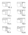
- Fig. 3 eine Fügeverbindung von Teilen des Gasgenerators nach dem Elektronenstrahl- oder Laserstrahlverfahren,
- Fig. 4 eine Fügeverbindung durch Schweißen, Schrumpfen oder Kleben,
- Fig. 5 eine Fügeverbindung durch Bördeln oder Döppern oder alternativ Schrumpfen oder Kleben,
- Fig. 6 eine Fügeverbindung durch Bördeln oder Rollen,
- Fig. 7 eine Fügeverbindung durch Reibschweißen einseitig,
- Fig. 8 eine Fügeverbindung durch Reibschweißen beidseitig einer Wand,
- Fig. 9 eine Fügeverbindung mittels Schrauben und Sichern,
- Fig. 10 eine Fügeverbindung durch Sicken und Rollen (Roll-Bond-Verfahren).
- 1 shows the gas generator in the assembled state (without filter inserts),
- 2 is an exploded view before assembly,
- 3 shows a joint connection of parts of the gas generator according to the electron beam or laser beam method,
- 4 shows a joint connection by welding, shrinking or gluing,
- 5 shows a joint connection by flanging or striking or alternatively shrinking or gluing,
- 6 shows a joint connection by flanging or rolling,
- 7 shows a joint connection by friction welding on one side,
- 8 shows a joint connection by friction welding on both sides of a wall,
- 9 shows a joint connection by means of screws and securing,
- 10 shows a joint connection by beading and rolling (roll-bond method).
Wie Fig. 1 zeigt, besitzt der Gasgenerator eine Gaserzeugungskammer 1 und wenigstens eine vorzugsweise zwei Filterkammern 2 und 3, wobei diese Hauptteile aus Blech gefertigt und zusammengefügt werden, zu einer im wesentlichen röhrförmigen zylindrischen Baueinheit, wie sie in Fig. 1 dargestellt ist. Weitere Einzelheiten sind aus der nachfolgenden Beschreibung ersichtlich.As shown in FIG. 1, the gas generator has a gas generation chamber 1 and at least one, preferably two
In Fig. 3 ist der modulartige Aufbau des Gasgenerator vor seinem Zusammenbau ersichtlich. In Fig. 1 und in Fig. 2 nicht dargestellt sind die Filtereinsätze wie an sich bekannt (vgl. eingangsgenannter Automobiltechn. Zeitschrift). Die genannten Hauptteile 1 bis 3 sind in Blechbauweise ausgeführt, wobei die Verwendung von Blechen bereits beschrieben ist in der Deutschen Auslegeschrift 29 15 202 der Anmelderin. Die dort beschriebenen dünnen Bleche sind auch hier anwendbar, ebenso die Treibsätze, Zünder etc..3 shows the modular structure of the gas generator before it is assembled. The filter inserts are not shown in FIG. 1 and in FIG. 2 as is known per se (cf. the automobile technology magazine mentioned at the beginning). The main parts 1 to 3 mentioned are designed in sheet metal construction, the use of sheets having already been described in the applicant's German specification 29 15 202. The thin sheets described there can also be used here, as can the propellants, detonators etc.
Die Erfindung unterscheidet sich vom Stand der Technik wesentlich durch den neuartigen Aufbau und Zusammenbau.
Die Gaserzeugungskammer 1 enthält den Treibsatz und den Zünder bzw. die Anzündeinheit 4 zum elektrischen Initiieren einer Zündung der Zündpillen des Treibsatzes von außen, insbesondere wenn eine Sensorschaltung einen Crashfall ermittelt hat, zwecks Aufblasen des Schutzkissens.The invention differs from the prior art essentially by the novel structure and assembly.
The gas generation chamber 1 contains the propellant charge and the igniter or ignition unit 4 for electrically initiating an ignition of the squibs of the propellant charge from the outside, in particular if a sensor circuit has determined a crash in order to inflate the protective cushion.
Bei der Erfindung bildet die Gaserzeugungskammer 1 das Zentrum an das angebaut wird. Sie besteht aus den Teilen 1a und 1b, welche ungleich sind, um fertigungstechnische Vorteile, insbesondere beim Schweißen zu ermöglichen. Die Filterkammern 2 und 3 werden an die zentrale Gaserzeugungskammer angefügt so, daß die Filterkammern 2 bzw. 3 in axialer Richtung der Hauptachse (Längsachse) der Gaserzeugungskammer 1 angeordnet sind. Die Gaserzeugungskammer 1 enthält den pyrotechnischen Treibsatz und entwickelt Druckgas, wenn von dem zentral jedoch um 90° zur Längs achse versetzt angeordneten Zünder 4 ein Zündimpuls von außen erhalten wird. Das erzeugte Druckgas wird durch die Düsenöffnungen 10 in den Düsenplatten 1c zu der oder den Filterkammern 2/3 durchströmt, dabei verwirbelt und umgelenkt, in dem es die Längsschlitze 20, 30 in den Filterkammern 2, 3 peripher (radial) verläßt, wobei die mit Öffnungen versehene periphere Austrittswand jeder Filterkammer den Mantel des Gasgenerator-Gehäuses bildet, der mit der Schutzeinrichtung verbunden ist.In the invention, the gas generation chamber 1 forms the center to which it is attached. It consists of
Bei der Erfindung werden die Hauptteile so zu einer zylinderförmigen Einheit zusammengefügt. Die Hauptteile sind napfförmig ausgebildet und die Näpfe bzw. Töpfe sind im Bereich der Kreisflächen (Düsenplatten oder Scheiben) aneinander gefügt. Diese Kreisflächen bilden die Stirnseiten. Die aneinander Fügung kann flächenhaft, linienhaft oder mittels vieler Punkte geschehen, entweder peripher oder über die Kreisflächen verteilt, je nach angewandtem Fügeverfahren und Fügemitteln und zu fügenden Materialien.In the invention, the main parts are assembled into a cylindrical unit. The main parts are cup-shaped and the bowls or pots are joined together in the area of the circular surfaces (nozzle plates or disks). These circular areas form the end faces. The joining together can be flat, linear or by means of many points, either peripherally or distributed over the circular areas, depending on the joining method and joining agents and materials to be joined.
Bei dem Gasgenerator der Erfindung wird die Gaserzeugungskammer das Zentralmodul bilden und die Filterkammern 2, 3 werden an dieses mit ihren Stirnseiten angebaut, so daß die verlängerte Hauptachse des Teils 1 auch die Hauptachse der Teile 2 und 3 bildet. Die Düsenplatten oder Scheiben, welche eben oder gewölbt ausgeführt werden können, weisen eine solche Anzahl von Düsen auf, die sowohl nach Zahl ,Größe und Verteilung vom Fachmann nach gewünschter Strömung ausgewählt werden, d.h. wenn eine stärkere Verwirbelung gewünscht wird, wird insbesondere ihre Zahl erhöht werden. Die Gaserzeugungskammer 1 wird erst zusammengesetzt, wenn der Treibsatz eingefüllt ist. Gleiches gilt für die Filterkammern 2 und 3 bezüglich der Filter. Die Filterkammern 2 und 3 werden dann symethrisch angefügt an die Gaserzeugungskammer 1 und zwar symethrisch bezogen auf die Mittelachse des Zünders 4, der seinerseits einen 90°-Winkel zur Hauptachse des Zylinders bildet, jedoch zentral innerhalb der zusammengefügten Gaserzeugungskammer, im Beispiel genau mittig angeordnet ist. Der Zünder ist als solcher ebenfalls in einem napfförmigen Gehäuse angeordnet und dieses napfförmige Gehäuse 4b wird an das Blechgehäuse der Gaserzeugungskammer 1 fest und dicht eingefügt. Die Druckerzeugungskammer 1 weist die größte Wandstärke auf, weils sie am höchsten druckbelastet wird und die Teile 2 und 3 eine geringere Wandstärke als Teil 1.In the gas generator of the invention, the gas generating chamber will form the central module and the
Die Teile des Gasgenerators bestehen - wie an sich bekannt - aus Blechen und bevorzugt aus gleichen oder ähnlichen Materialien, insbesondere jedoch aus fügeverträglichen Materialien.As is known per se, the parts of the gas generator consist of sheets and preferably of the same or similar materials, but in particular of materials that are compatible with joining.
Als besonders geeignet erwiesen haben sich die folgenden Fügeverfahren: Elektronenstrahlschweißen, Laserstrahlschweißen, Reibschweißen, Schrumpfen, Metallkleben mit Klebstoffen wie aus der Luft- und Raumfahrt bekannt, weil auch dort gleiche oder ähnliche metallische Leichtbaumaterialien verwandt werden.
Ebenso verwendet werden kann ein Bördeln oder Döppern oder ein Rollen (Roll-Bond-Verfahren) sowie das Schrauben und Sichern (dabei Abdichten).The following joining methods have proven to be particularly suitable: electron beam welding, laser beam welding, friction welding, shrinking, metal gluing with adhesives as known from aerospace because the same or similar metallic lightweight materials are used there as well.
Flanging or striking or rolling (roll-bond process) as well as screwing and securing (thereby sealing) can also be used.
Wesentlich ist, daß hier korrosionsfeste Materialien verwendet werden, wegen der chemischen Aggressivität des Treibsatzes und daß die verwendeten Materialien in solcher Wandstärke ausgeführt werden, daß sie den anstehenden Druckbelastungen standhalten. Die weitere Forderung ist die absolute Dichtheit der Fügeverbindungen.It is essential that corrosion-resistant materials are used here because of the chemical aggressiveness of the propellant charge and that the materials used are made with such a wall thickness that they can withstand the pressure loads that are present. The further requirement is the absolute tightness of the joint connections.
Der Fachmann wird daher unter diesen vorstehenden vorallem sicherheitstechnischen aber auch nach fertigungstechnischen sowie wirtschaftlichen Gesichtspunkten seine Auswahl treffen, insbesondere hinsichtlich des anzuwendenden Fügeverfahrens. Dabei kann er selbstverständlich verschiedene Fügeverfahren miteinander kombinieren, d.h. Fügestellen, Linien oder Flächen zwischen den zusammenzufügenden Teilen nicht nur nach gleichem Verfahren (sämtlich) sondern auch nach verschiedenen Verfahren zusammenfügen.The person skilled in the art will therefore make his selection from the above, above all in terms of safety technology, but also in terms of production technology and economy, in particular with regard to the joining method to be used. Of course, he can combine different joining processes with each other, i.e. Join joints, lines or areas between the parts to be joined not only using the same procedure (all) but also using different procedures.
In den Fig. 3 bis 10 sind die einzelnen Fügeverfahren rein beispielsweise anhand jeweils einer einzelnen Fügestelle zwischen Hauptteilen 1, 2, 3 im Detail dargestellt ohne daß es einer besonderen Erläuterung hierfür bedarf.3 to 10, the individual joining methods are shown in detail purely, for example, with the aid of a single joining point between
Claims (17)
- die Gaserzeugungskammer (1) das Zentrum bildet, an das mit jeweils kleinstmöglicher druckbeaufschlagter Fläche form- oder stoffschlüssig,
- eine/mehrere Filterkammer(n) (2,3) angefügt wird/werden, so daß
- die Filterkammer(n) (2,3) in axialer Richtung der Hauptachse der Gaserzeugungskammer angeordnet ist/sind, wobei Druckgas entsteht, wenn der pyrotechnische Treibsatz vom seinerseits zentral in der als kesselartige Druckkammer ausgebildeten Gaserzeugungskammer angeordneten Zünder einen Impuls zum Zünden erhält,
- das erzeugte Druckgas nach axialem Durchströmen der Filterkammer(n) (2,3) diese nach Umlenkung peripher (radial) verläßt, wobei die mit Öffnungen versehene periphere Austrittswand den Mantel des Gasgenerator-Gehäuses bildet, das mit der Schutzeinrichtung verbunden ist.1. Gas generator, containing a gas generating chamber with igniter for a propellant charge and at least one filter chamber, these main parts being made of sheet metal and assembled for use in an impact protection device for protecting occupants of a vehicle, characterized in that
- The gas generation chamber (1) forms the center to which, with the smallest possible pressurized surface, form-fitting or material-locking,
- One / more filter chamber (s) (2,3) is / are added so that
the filter chamber (s) (2, 3) is / are arranged in the axial direction of the main axis of the gas generation chamber, compressed gas being produced when the pyrotechnic propellant receives a pulse for ignition from the igniter, which in turn is arranged centrally in the gas generation chamber designed as a boiler-like pressure chamber,
- After the axial flow through the filter chamber (s) (2, 3), the pressurized gas generated leaves the peripheral (radial) after deflection, the openings provided with a peripheral outlet wall forming the jacket of the gas generator housing, which is connected to the protective device.
Applications Claiming Priority (2)
| Application Number | Priority Date | Filing Date | Title |
|---|---|---|---|
| DE3832120 | 1988-09-21 | ||
| DE3832120A DE3832120C3 (en) | 1988-09-21 | 1988-09-21 | Gas generator |
Publications (2)
| Publication Number | Publication Date |
|---|---|
| EP0359902A2 true EP0359902A2 (en) | 1990-03-28 |
| EP0359902A3 EP0359902A3 (en) | 1991-04-17 |
Family
ID=6363443
Family Applications (1)
| Application Number | Title | Priority Date | Filing Date |
|---|---|---|---|
| EP19890107124 Withdrawn EP0359902A3 (en) | 1988-09-21 | 1989-04-20 | Gasgenerator |
Country Status (6)
| Country | Link |
|---|---|
| US (1) | US5000479A (en) |
| EP (1) | EP0359902A3 (en) |
| JP (1) | JPH02141351A (en) |
| KR (1) | KR0136659B1 (en) |
| CA (1) | CA1322382C (en) |
| DE (1) | DE3832120C3 (en) |
Cited By (4)
| Publication number | Priority date | Publication date | Assignee | Title |
|---|---|---|---|---|
| AU626063B1 (en) * | 1990-03-26 | 1992-07-23 | Morton International, Inc. | Two-stage automotive gas bag inflator using igniter material to delay second stage ignition |
| WO1995005297A1 (en) * | 1993-08-18 | 1995-02-23 | PRECISION ENGINEERING COMPANY, a division of PECO TOOL & DIE LTD | Air bag inflator |
| EP0704347A1 (en) * | 1994-09-23 | 1996-04-03 | TEMIC Bayern-Chemie Airbag GmbH | Gas generator |
| WO1997023368A1 (en) * | 1995-12-22 | 1997-07-03 | Trw Airbag Systems Gmbh & Co.Kg. | Gas generator for an airbag system |
Families Citing this family (60)
| Publication number | Priority date | Publication date | Assignee | Title |
|---|---|---|---|---|
| DE4028715A1 (en) * | 1990-04-09 | 1991-10-10 | Alfred Kroiss | GAS PILLOW IMPACT PROTECTOR |
| DE4016046A1 (en) * | 1990-05-18 | 1991-11-21 | Bayern Chemie Gmbh Flugchemie | Vehicle passenger safety device - uses gas bag inflated via gas generator under control of impact sensor, forming modular unit |
| JPH0478639A (en) * | 1990-07-16 | 1992-03-12 | Asahi Chem Ind Co Ltd | Air bag inflator |
| EP0488937B1 (en) * | 1990-11-28 | 1996-01-24 | Dynamit Nobel Aktiengesellschaft | Detonator, in particular for the gas generator of a passenger protective device in an automotive vehicle |
| JPH04283148A (en) * | 1990-11-28 | 1992-10-08 | Dynamit Nobel Ag | Gas generator |
| JP3115381B2 (en) * | 1990-11-28 | 2000-12-04 | デイナミート ノーベル アクチエンゲゼルシヤフト | Gas generators for airbags, especially tubular gas generators |
| US5269560A (en) * | 1990-12-18 | 1993-12-14 | Twr Inc. | Initiator assembly for air bag inflator |
| US5199741A (en) * | 1990-12-18 | 1993-04-06 | Trw Inc. | Method of assembling an inflator |
| US5201542A (en) * | 1991-07-10 | 1993-04-13 | Breed Automotive Corporation | Two piece inflator housing |
| EP0589035B1 (en) * | 1992-03-19 | 1996-05-08 | TEMIC Bayern-Chemie Airbag GmbH | Gas generator system |
| JPH05286405A (en) * | 1992-04-15 | 1993-11-02 | Daicel Chem Ind Ltd | Gas generator for air bag |
| DE4316614A1 (en) * | 1992-05-18 | 1993-11-25 | Trw Vehicle Safety Systems | Inflating system for vehicle air-bag - has two housing elements coupled together to form closed chamber with first housing element having container for inflation flow medium source |
| US5611566A (en) * | 1992-08-20 | 1997-03-18 | Temic Bayern-Chemie Airbag Gmbh | Gas generator for a safety system for protecting occupants in motor vehicles |
| US5443286A (en) * | 1992-10-09 | 1995-08-22 | Morton International, Inc. | Gas generator for vehicle occupant restraint system |
| US5531474A (en) * | 1994-04-26 | 1996-07-02 | Breed Automotive Technology, Inc. | Inflator assembly |
| US5513879A (en) * | 1994-05-04 | 1996-05-07 | Breed Automotive Technology, Inc. | Two stage inflator with module venting for passenger side airbags |
| US5483896A (en) * | 1994-07-12 | 1996-01-16 | Morton International, Inc. | Pyrotechnic inflator for an air bag |
| US5556130A (en) * | 1994-10-05 | 1996-09-17 | Morton International, Inc. | Single side wall air bag inflator |
| US5482316A (en) * | 1994-10-27 | 1996-01-09 | Morton International, Inc. | Air bag inflators having housings with crimp-formed joints |
| US5458371A (en) * | 1994-10-27 | 1995-10-17 | Morton International, Inc. | Crimp-formed joint housings for air bag inflators |
| DE19505580A1 (en) * | 1995-02-18 | 1996-08-22 | Dynamit Nobel Ag | Gas generator in sheet metal construction for a motor vehicle occupant protection device |
| US5542702A (en) * | 1995-03-27 | 1996-08-06 | Morton International, Inc. | Pressurized gas inflator for vehicle occupant protection systems |
| US5799973A (en) * | 1995-04-22 | 1998-09-01 | Temic Bayern-Chemie Airbag Gmbh | Pyrotechnic gas generator with two separate combustion chambers |
| US5536040A (en) * | 1995-04-24 | 1996-07-16 | Trw Inc. | Inflator for side impact air bag |
| DE19519605A1 (en) * | 1995-05-29 | 1996-04-04 | Daimler Benz Ag | Airbag high pressure reservoir for motor vehicles |
| DE19532023A1 (en) * | 1995-08-31 | 1997-03-06 | Temic Bayern Chem Airbag Gmbh | Device for filling a restraint device |
| DE19535028A1 (en) * | 1995-09-21 | 1997-03-27 | Temic Bayern Chem Airbag Gmbh | Gas generator esp. for passive retention systems in automobiles |
| US5759219A (en) * | 1995-09-22 | 1998-06-02 | Morton International, Inc. | Unitary drop-in airbag filters |
| US5746793A (en) * | 1996-01-16 | 1998-05-05 | Morton International, Inc. | Reinforced ceramic air bag filters |
| DE19602696A1 (en) * | 1996-01-26 | 1997-07-31 | Temic Bayern Chem Airbag Gmbh | Gas generator for an airbag system of a vehicle |
| DE19608392A1 (en) * | 1996-03-05 | 1997-09-11 | Temic Bayern Chem Airbag Gmbh | Gas generator |
| DE19620758A1 (en) * | 1996-05-23 | 1997-11-27 | Temic Bayern Chem Airbag Gmbh | Gas-generator for motor vehicle occupant protection airbag system |
| DE19635766C2 (en) * | 1996-09-04 | 1998-10-08 | Steinmueller Gmbh L & C | Method of welding a nipple to a tubular collector and collector assembly |
| US5716072A (en) * | 1996-09-17 | 1998-02-10 | United Technologies Corporation | Airbag gas generator with snap joint connection |
| US5887893A (en) * | 1996-11-21 | 1999-03-30 | Autoliv Asp, Inc. | Necked airbag inflator |
| DE19728438A1 (en) * | 1997-07-03 | 1999-01-07 | Temic Bayern Chem Airbag Gmbh | Pyrotechnic gas generator |
| DE19735501C2 (en) * | 1997-08-16 | 2001-11-22 | Axel Braunschaedel | Gas generator for an airbag |
| DE19757478A1 (en) * | 1997-12-23 | 1999-06-24 | Dynamit Nobel Ag | Pyrotechnic gas generator for passive retention system in road vehicle |
| DE29802731U1 (en) * | 1998-02-17 | 1998-06-10 | Trw Occupant Restraint Systems Gmbh, 73551 Alfdorf | Airbag module |
| DE19813708B4 (en) * | 1998-03-27 | 2004-02-05 | Trw Airbag Systems Gmbh & Co. Kg | Tubular gas generator |
| DE19817485A1 (en) * | 1998-04-20 | 1999-10-21 | Trw Airbag Sys Gmbh & Co Kg | Gas generator especially for a vehicle occupant restraint system |
| DE29819168U1 (en) | 1998-10-27 | 1999-03-04 | TRW Airbag Systems GmbH & Co. KG, 84544 Aschau | Gas generator, in particular for vehicle occupant restraint systems |
| JP3772570B2 (en) * | 1999-02-12 | 2006-05-10 | タカタ株式会社 | Gas generator, its container and container manufacturing method |
| DE19942910A1 (en) * | 1999-09-08 | 2001-03-15 | Delphi Tech Inc | Air sack gas generator housing has second part with attachment arrangement for holding gas generator in installed position, for connection to first part in defined pre-assembly position |
| DE10020285A1 (en) * | 2000-04-26 | 2001-07-12 | Wilhelm Biemold | Drive unit esp. for tensioning the safety belt in motor vehicles has drive element executing a rotary movement when a propellant gas is generated by ignition of a charge |
| JP4631189B2 (en) * | 2001-03-21 | 2011-02-16 | タカタ株式会社 | Gas generator |
| WO2003082633A2 (en) * | 2002-03-27 | 2003-10-09 | Automotive Systems Laboratory, Inc. | Weld-less driver-side inflator |
| DE10240640B3 (en) | 2002-09-03 | 2004-02-12 | Trw Airbag Systems Gmbh & Co. Kg | Gas generator casing manufacturing process involves friction welding to depth less than tube wall thickness |
| US6957761B2 (en) * | 2003-04-08 | 2005-10-25 | Autoliv Asp, Inc. | Inertia or friction welding of conical components into elliptically-shaped holes in a pipe or tube |
| DE20306818U1 (en) * | 2003-05-02 | 2003-09-11 | TRW Occupant Restraint Systems GmbH & Co. KG, 73553 Alfdorf | The gas bag module |
| US7140638B2 (en) | 2004-04-06 | 2006-11-28 | Trw Vehicle Safety Systems, Inc. | Inflator filter retainer |
| DE202004017428U1 (en) * | 2004-11-10 | 2005-01-27 | Trw Airbag Systems Gmbh | Gas generator and gas bag module |
| DE102005015788B3 (en) * | 2005-04-06 | 2006-10-05 | Trw Airbag Systems Gmbh | Manufacture of gas generator involves making tubular body with aperture, mounting housing on it and joining them by capacitor discharge welding |
| DE102006041628A1 (en) * | 2005-09-13 | 2007-04-19 | Neumayer Tekfor Holding Gmbh | Combustion chamber, especially for airbags, has barrel-shaped body with thicker walls in outlet and ignition chamber fixing zones |
| US8662532B2 (en) | 2010-11-10 | 2014-03-04 | Autoliv Asp, Inc. | Inflator having a mechanically coupled two-piece housing |
| DE102011107749B4 (en) * | 2011-07-14 | 2017-03-09 | Trw Airbag Systems Gmbh | A method of attaching a lighter in a lighter holder and assembly to a lighter holder |
| DE102012023031B4 (en) | 2012-11-26 | 2023-02-23 | Zf Automotive Germany Gmbh | Belt tensioner for a vehicle occupant restraint system |
| JP6633985B2 (en) * | 2016-07-20 | 2020-01-22 | 株式会社ダイセル | Gas generator |
| CN110723098B (en) * | 2019-10-14 | 2021-02-26 | 华懋(厦门)新材料科技股份有限公司 | Outer casing assembly of safety airbag gas generator |
| CN115959079B (en) * | 2022-12-22 | 2026-01-30 | 湖北航鹏化学动力科技有限责任公司 | Gas generators and automobiles |
Family Cites Families (13)
| Publication number | Priority date | Publication date | Assignee | Title |
|---|---|---|---|---|
| US1779843A (en) * | 1927-02-10 | 1930-10-28 | Hirsch Sons Inc G | Dispensing package |
| GB743366A (en) * | 1952-08-20 | 1956-01-11 | Olin Mathieson | Improvements in or relating to igniter cartridges |
| FR2116948A5 (en) * | 1970-12-11 | 1972-07-21 | France Etat | |
| DE2330194C3 (en) * | 1973-06-14 | 1978-07-06 | Bayern-Chemie Gesellschaft Fuer Flugchemische Antriebe Mbh, 8261 Aschau | Gas supply unit of an impact protection device for motor vehicle occupants |
| GB1518806A (en) * | 1974-11-29 | 1978-07-26 | Eaton Corp | Fluid supply source for inflating an expandable confinement of a vehicle occupant restraint system |
| JPS52121242A (en) * | 1976-04-05 | 1977-10-12 | Daicel Chem Ind Ltd | Gas generator for gas bag |
| DE2824701C2 (en) * | 1978-06-06 | 1982-11-11 | Bayern-Chemie Gesellschaft für flugchemische Antriebe mbH, 8261 Aschau | Gas generator |
| DE2915202B2 (en) * | 1979-04-14 | 1981-02-19 | Bayern-Chemie Gesellschaft Fuer Flugchemische Antriebe Mbh, 8261 Aschau | Sheet metal gas generator |
| EP0092031B1 (en) * | 1982-04-15 | 1984-12-27 | Firmenich Sa | 1(7)p-menthene-9-al and its use as a perfuming and flavouring agent |
| US4698107A (en) * | 1986-12-24 | 1987-10-06 | Trw Automotive Products, Inc. | Gas generating material |
| DE3742656A1 (en) * | 1987-05-22 | 1988-12-08 | Dynamit Nobel Ag | GAS GENERATOR FOR AN AIRBAG |
| JPS6441440A (en) * | 1987-08-06 | 1989-02-13 | Daicel Chem | Gas generator |
| US4796912A (en) * | 1987-11-12 | 1989-01-10 | Morton Thiokol, Inc. | Elongate gas generator for inflating vehicle inflatable restraint cushions |
-
1988
- 1988-09-21 DE DE3832120A patent/DE3832120C3/en not_active Expired - Fee Related
-
1989
- 1989-04-20 EP EP19890107124 patent/EP0359902A3/en not_active Withdrawn
- 1989-05-30 KR KR1019890007204A patent/KR0136659B1/en not_active Expired - Fee Related
- 1989-08-04 JP JP1201484A patent/JPH02141351A/en active Pending
- 1989-09-20 CA CA000612051A patent/CA1322382C/en not_active Expired - Fee Related
- 1989-09-21 US US07/410,624 patent/US5000479A/en not_active Expired - Fee Related
Cited By (4)
| Publication number | Priority date | Publication date | Assignee | Title |
|---|---|---|---|---|
| AU626063B1 (en) * | 1990-03-26 | 1992-07-23 | Morton International, Inc. | Two-stage automotive gas bag inflator using igniter material to delay second stage ignition |
| WO1995005297A1 (en) * | 1993-08-18 | 1995-02-23 | PRECISION ENGINEERING COMPANY, a division of PECO TOOL & DIE LTD | Air bag inflator |
| EP0704347A1 (en) * | 1994-09-23 | 1996-04-03 | TEMIC Bayern-Chemie Airbag GmbH | Gas generator |
| WO1997023368A1 (en) * | 1995-12-22 | 1997-07-03 | Trw Airbag Systems Gmbh & Co.Kg. | Gas generator for an airbag system |
Also Published As
| Publication number | Publication date |
|---|---|
| US5000479A (en) | 1991-03-19 |
| KR900004558A (en) | 1990-04-12 |
| CA1322382C (en) | 1993-09-21 |
| DE3832120C3 (en) | 1997-03-13 |
| DE3832120C2 (en) | 1991-07-11 |
| EP0359902A3 (en) | 1991-04-17 |
| KR0136659B1 (en) | 1998-04-27 |
| DE3832120A1 (en) | 1990-03-22 |
| JPH02141351A (en) | 1990-05-30 |
Similar Documents
| Publication | Publication Date | Title |
|---|---|---|
| EP0359902A2 (en) | Gasgenerator | |
| DE69707629T2 (en) | Integral, tubular, pyrotechnic gas generator for inflating airbags | |
| DE69113495T2 (en) | Structure and method for assembling an airbag module. | |
| DE4135299C2 (en) | Gas generator | |
| DE69802025T2 (en) | Pyrotechnic gas generator with adjustable throughput and volume for an airbag | |
| DE69825803T2 (en) | A method of securing a progressive deployment of an airbag and pyrotechnic charge for use in such a method | |
| DE4019877C2 (en) | ||
| EP0738631A1 (en) | Pyrotechnic gas generator with two separated combustion chambers | |
| DE69908061T2 (en) | Gas generator | |
| DE4222780A1 (en) | TWO-PIECE HOUSING FOR AN AIRBAG INFLATION SYSTEM | |
| DE69608860T2 (en) | Hot gas generating pyrotechnic gas generator for side impact protection airbag | |
| DE2824701C2 (en) | Gas generator | |
| DE4419549A1 (en) | Inflation device for an air or gas bag device | |
| DE1918046C3 (en) | Ignition device | |
| DE69014499T2 (en) | Gas generator. | |
| EP0782945A1 (en) | Gas generator for a vehicle restraint system | |
| EP1669257B1 (en) | Gas generator | |
| DE9307940U1 (en) | Gas generator, in particular a mechanically triggerable gas generator | |
| DE69303446T2 (en) | GAS GENERATOR WITH EXTERNAL CONNECTIONS | |
| DE60114066T2 (en) | Multi-stage rocket motor with an interstage protection device | |
| DE69809860T2 (en) | Adaptable pyrotechnic gas generator for an airbag with neutralizing device | |
| DE2150744C3 (en) | Impact protection system for the occupants of a motor vehicle | |
| EP0265608A2 (en) | Device for the ejection of containers, particularly ammunition | |
| EP0891268B2 (en) | Gas generator | |
| DE2306872A1 (en) | Explosives article containing pyrometal - spec. (H enriched) palladium, for promoting ignition |
Legal Events
| Date | Code | Title | Description |
|---|---|---|---|
| PUAI | Public reference made under article 153(3) epc to a published international application that has entered the european phase |
Free format text: ORIGINAL CODE: 0009012 |
|
| AK | Designated contracting states |
Kind code of ref document: A2 Designated state(s): DE FR GB IT SE |
|
| PUAL | Search report despatched |
Free format text: ORIGINAL CODE: 0009013 |
|
| AK | Designated contracting states |
Kind code of ref document: A3 Designated state(s): DE FR GB IT SE |
|
| 17P | Request for examination filed |
Effective date: 19910426 |
|
| 17Q | First examination report despatched |
Effective date: 19921110 |
|
| 18W | Application withdrawn |
Withdrawal date: 19921128 |
|
| STAA | Information on the status of an ep patent application or granted ep patent |
Free format text: STATUS: THE APPLICATION HAS BEEN WITHDRAWN |
|
| R18W | Application withdrawn (corrected) |
Effective date: 19921128 |