EP0704347A1 - Gas generator - Google Patents
Gas generator Download PDFInfo
- Publication number
- EP0704347A1 EP0704347A1 EP95113832A EP95113832A EP0704347A1 EP 0704347 A1 EP0704347 A1 EP 0704347A1 EP 95113832 A EP95113832 A EP 95113832A EP 95113832 A EP95113832 A EP 95113832A EP 0704347 A1 EP0704347 A1 EP 0704347A1
- Authority
- EP
- European Patent Office
- Prior art keywords
- gas generator
- combustion chamber
- generator according
- ignition
- opening
- Prior art date
- Legal status (The legal status is an assumption and is not a legal conclusion. Google has not performed a legal analysis and makes no representation as to the accuracy of the status listed.)
- Granted
Links
Images


Classifications
-
- B—PERFORMING OPERATIONS; TRANSPORTING
- B60—VEHICLES IN GENERAL
- B60R—VEHICLES, VEHICLE FITTINGS, OR VEHICLE PARTS, NOT OTHERWISE PROVIDED FOR
- B60R21/00—Arrangements or fittings on vehicles for protecting or preventing injuries to occupants or pedestrians in case of accidents or other traffic risks
- B60R21/02—Occupant safety arrangements or fittings, e.g. crash pads
- B60R21/16—Inflatable occupant restraints or confinements designed to inflate upon impact or impending impact, e.g. air bags
- B60R21/26—Inflatable occupant restraints or confinements designed to inflate upon impact or impending impact, e.g. air bags characterised by the inflation fluid source or means to control inflation fluid flow
- B60R21/264—Inflatable occupant restraints or confinements designed to inflate upon impact or impending impact, e.g. air bags characterised by the inflation fluid source or means to control inflation fluid flow using instantaneous generation of gas, e.g. pyrotechnic
- B60R21/2644—Inflatable occupant restraints or confinements designed to inflate upon impact or impending impact, e.g. air bags characterised by the inflation fluid source or means to control inflation fluid flow using instantaneous generation of gas, e.g. pyrotechnic using only solid reacting substances, e.g. pellets, powder
-
- B—PERFORMING OPERATIONS; TRANSPORTING
- B60—VEHICLES IN GENERAL
- B60R—VEHICLES, VEHICLE FITTINGS, OR VEHICLE PARTS, NOT OTHERWISE PROVIDED FOR
- B60R21/00—Arrangements or fittings on vehicles for protecting or preventing injuries to occupants or pedestrians in case of accidents or other traffic risks
- B60R21/02—Occupant safety arrangements or fittings, e.g. crash pads
- B60R21/16—Inflatable occupant restraints or confinements designed to inflate upon impact or impending impact, e.g. air bags
- B60R21/20—Arrangements for storing inflatable members in their non-use or deflated condition; Arrangement or mounting of air bag modules or components
Definitions
- the invention relates to a gas generator, in particular for passive restraint systems in motor vehicles according to the preamble of patent claim 1.
- Restraint systems for vehicle occupants are known which are equipped with a gas bag (airbag) which is inflated by a gas generated by a gas generator.
- a gas bag airbag
- gas generators There are essentially two types of gas generators known that use combustible solid fuel gas generating compositions to inflate the air bag.
- a gas generator is known from DE 42 08 844 A1, the combustion and filter chambers of which are arranged in a ring around an ignition unit and are constructed from shell-shaped individual parts.
- a shell-shaped lower part is connected to a shell-shaped upper part to form the gas generator housing by means of two threads, namely on the one hand to connect the cylindrical inner walls and on the other hand to connect the cylindrical outer walls of the lower and upper parts. Since these two threads have to grip simultaneously when assembling the gas generator housing, extremely small tolerances are permissible for these, since otherwise these threads never fit together correctly. This also leads to the fact that these tight tolerances required for the threads at high manufacturing costs of the lower and upper part.
- Another disadvantage of using threads is that securing means such as glue, inserts, claws and pins are required to secure them and to seal the gas generator housing.
- a gas generator with a cylindrical structure is known from DE 43 38 536 A1, in which an elongated cylinder represents the combustion chamber and a cylinder enclosing this combustion chamber cylinder has the outlet openings.
- the combustion chamber cylinder is closed at the end with a cover, a thread also being provided as the connecting means.
- the use of such a thread also leads to the disadvantages already mentioned above.
- the invention is therefore based on the object of creating gas generators of the type mentioned, the individual parts of which are connected to one another without the use of threads.
- the housing of which is constructed from an upper and lower part
- the inner and outer walls of the lower part have first mechanical latching means and the inner and outer walls of the upper part have second mechanical latching means on that work together so that a latch lock is formed.
- An embodiment of the cylindrical gas generator according to the invention provides that first and second mechanical latching means are also provided for connecting the cover to the combustion chamber cylinder, which engage in such a way that a pawl lock is formed.
- the overall height is always clearly determined when assembling the housing comprising the upper and lower part, which is not the case when using threads, since the overall height is dependent on the screw depth.
- latching means leads to a simpler assembly of the gas generator according to the invention, whereby further cost advantages are achieved.
- the number of rejects in the assembly of a gas generator constructed from the upper and lower part is reduced, since the four threaded parts used in the prior art no longer fit together even with the smallest tolerance fluctuations.
- the ignition unit has a circumferential bead which is received in an annular groove formed by the upper and lower part. This results in a simpler assembly compared to the use of threaded or wobble rivets even when the igniter unit is installed.
- connection of the ignition unit to the combustion chamber cylinder is established via a latch lock.
- sealing elements in particular O-rings, are provided in the area of the latching means.
- the mechanical latching means are designed as slotted pawls, so that this creates a spring action, so that a reliable functioning of the latching mechanism is ensured.
- a rotary bayonet lock can be provided as a latch lock.
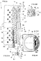
- FIG. 1 shows a lower part 2 and an upper part 3, each of which is circularly symmetrical in order to form, in the assembled state, a housing 1 according to FIG. 2 for a gas generator which receives a gas-generating composition 43.
- This housing 1 contains a cylindrical ignition chamber 9 for receiving an ignition unit 19 and an ignition mixture 20, the axis of rotation of this ignition chamber 9 forming the axis of symmetry of the rotationally symmetrical housing 1.
- a toroidal combustion chamber 8 is placed around this ignition chamber 9.
- another torroid zone forms a filter chamber 10.
- the lower and upper parts 2 and 3 shown in FIG. 1, which are each cup-shaped, are used to form this chamber system.
- the upper and lower parts 2 and 3 each have a cylindrical inner wall 4 or 6 and a cylindrical outer wall 5 or 7, which are each formed coaxially with one another.
- the inner walls 4 and 6 of the lower and upper part 2 and 3 together form the ignition chamber 9, while the two outer walls 5 and 7 together form the outer boundary of the combustion chamber 8.
- the filter chamber 10 is finally formed by a filter chamber wall 5a flanged to the lower part 2 and a part 29 shown in FIG.
- the inner walls 4 and 6 and the outer walls 5 and 7 are pushed concentrically into one another, which is why the outer diameter of the cylindrical inner wall 6 of the upper part 3 corresponds to the inner diameter of the cylindrical inner wall 4 of the lower part 2.
- the cylindrical outer walls 5 and 7 of the lower part 2 and the lower part 3 are formed so that the outer wall 7 of the upper part 3 encloses the outer wall 5 of the lower part 2.
- latching means consist in particular of latching pawls 11a and 11b which are arranged on the outer edges of the cylindrical inner wall as well as on the cylindrical outer wall and are slotted (see reference numeral 11c), so that a spring effect is produced.
- This spring action is necessary because when the lower part 2 and the upper part 3 are pushed together, the pawl elements 11a are pretensioned outwards and the pawl elements 11b inwards, so that in the pushed-together state the pawl elements 11a and 11b snap into undercuts 12a and 12b provided in the upper part 3.
- the pawl parts 11a and 11b pretension about 1.5-2 mm during the compression of the lower part 2 and the upper part 3.
- the lower part 2 In order to insert the ignition unit 19 (cf. FIG. 2) into the housing, the lower part 2 has an opening 41 in the bottom region of the ignition chamber 9, which opening is adapted to the diameter of the ignition unit 19.
- this ignition unit 19 is inserted as a wobble rivet after the assembly of the lower and upper part or screwed in by means of a thread.
- the ignition unit 19 is installed in a simple manner as follows.
- a circumferential ledge 38 is arranged in the edge region of the opening 41 in the base region of the ignition chamber 9 of the lower part 2.
- This ledge 38 forms, together with a circumferential step 39, which is arranged on the edge of the cylindrical inner wall 6 of the upper part 3, a circumferential groove in the assembled state of the lower and upper parts 2 and 3.
- a corresponding bead 40 formed on the circumference of the ignition unit 19 is received by this annular groove 42, so that a fit is produced in the assembled state.
- an O-ring 32 is inserted as a sealing element in the inner corner region of the ledge 38.
- a second sealing ring 32 lies in a circumferential step, which is arranged on the outer surface of the cylindrical outer wall 5 of the lower part 2. In the assembled state, the free end of the cylindrical outer wall 7 of the upper part 3 abuts this step provided with the O-ring.
- the lower part 2 and the lower part 3 are preassembled.
- an insulation band and a coarse filter 27 are introduced into the combustion chamber 8 of the lower part 2, which is arranged according to FIG. 2 in the region of outlet openings 25 arranged in the cylindrical outer wall 5.
- the gas-generating mass is then filled into the combustion chamber 8 in the form of tablets 43.
- these tablets 43 can also be introduced in a pre-packaging made of aluminum, this pre-packaging being adapted to the combustion chamber in a toroidal shape.
- a volume compensation means 37 is also inserted, which also acts as a damping cushion.
- the upper part 3 is preassembled by first inserting an outer dam sleeve 22 into the ignition chamber. Pre-ignition powder 21 is then filled in and then a separating film is pressed in. Now the actual ignition powder, the ignition mixture 20 is metered in and an inner dam sleeve 23 is pressed in. Finally, the ignition unit 19, which contains the actual squib with an ignition carrier, is also pressed in, so that the bead 40 bears against the circumferential step 39.
- the preassembled lower part and the preassembled upper part 3 can be pressed together, the pawl parts 11a and 11b pretensioning during the compression.
- the pawl parts 11a and 11b snap into the undercuts 12a and 12b, the sealing elements 32 deform and remain deformed even in the final state, so that the required tightness is automatically ensured.
- the height of the housing 1 is now clearly defined by the ratchet mechanism, and no longer depends as in If a thread is used, it depends on the screw depth.
- a metal wool 28 is introduced as a coarse filter in the area of the filter chamber wall 5a, a guide plate 30 with a fine filter 31 is installed and then a plate 26 with outlet openings 26 is clipped in.
- This now fully assembled gas generator 1 according to FIG. 2 can now also be connected to the holder of a steering wheel of a motor vehicle via an encircling flange attached to the filter chamber wall 5a with an inflatable bag as an airbag.
- the latch lock used in the exemplary embodiment according to FIGS. 1 and 2 can also be replaced by a rotary bayonet lock.
- the electrical ignition unit 19 receives a signal to ignite the ignition mixture 20, as a result of which the outer and inner insulating sleeves 22 and 23 tear open at a certain pressure in order to pass an ignition flame into the combustion chamber 8 via bores 24 arranged in the cylindrical inner wall 6 allow.
- the tablets 43 ignite to produce the necessary propellant gas, whereby the damming tape or when using the prepacking is torn open and the propellant gas enters the filter chamber 10 after passing through the coarse filter 27 through the outlet openings 25.
- These openings 25 are aligned so that the propellant gas from the combustion chamber 8 hits the metal wool 28 directly, where liquid and solid particles are separated from the gas.
- a Condensation for liquid particles from the gas stream begins at the coarse filter 27, which is located in front of the outlet openings 25. After the propellant gas has hit the metal wool 28, it is deflected by the baffle plate 30 and guided to the fine filter 31. The propellant then enters the inflatable bag through openings 26.
- Both the blow-out openings 26 and the outlet openings 24 can be sealed on their inside by thin bursting foils so that no moisture can penetrate from the outside.
- Aluminum is used as the housing material for the housing 1 of the gas generator according to the invention according to FIGS. 1 and 2.
- the gas generator according to Figures 3 and 4 has an elongated cylindrical shape and consists of the following parts: a combustion chamber cylinder 13, which receives the gas-generating fuel in the form of tablets 43 to form a combustion chamber 8, a cover 16 for closing the front opening 14 of the combustion chamber cylinder 13, an ignition unit 19 which projects through the other end opening 15 of the combustion chamber cylinder 13 into the combustion chamber 8 and closes the same, and an outer cylinder 17 surrounding the combustion chamber cylinder 13, filter media 18 being arranged in the space between these two cylinders 13 and 17 are.
- the cover 16 has a peripheral edge 16a which slips over the edge region at the opening 14 of the combustion chamber cylinder 18, this edge region 16a being provided with pawls 11 which, when the cover 16 is slipped over the opening 14 of the combustion chamber cylinder 13 snaps into recesses 12 made on the jacket of the combustion chamber cylinder 13.
- these latches 11 are slotted to ensure the necessary spring action when snapping into place.
- a sealant for example an O-ring 32, is inserted in the inner corner region before this cover 16 is installed.
- the cover 16 can also be provided with pawls 11 with edges 16a according to FIG. 3b, which, however, engage or engage in recesses 12 arranged on the inner surface of the combustion chamber cylinder 13.
- the pawls 11 are slotted.
- An O-ring 32 is also provided for sealing.
- the cover 16 can also be provided with two concentrically circumferential edges 16a (not shown in the figures), each of which has slotted pawls 11.
- the pawls on the outer edge are pretensioned outwards and the pawls on the inner edge inward and then latch simultaneously into recesses arranged on the outer surface and on the inner surface of the combustion chamber cylinder.
- a closure with particularly high tightness is hereby achieved.
- the second end opening 15 of the combustion chamber cylinder 18 has a smaller diameter than the combustion chamber cylinder and is adapted to the diameter of the ignition unit 19.
- both an inner flange 33 and an outer flange 34 are provided in the edge region of the opening 15. So the inner flange 33 on an inner stop for an outer dam sleeve 22.
- An inner dam sleeve 23 is pressed through the cylindrical space formed by the inner and outer flanges 33 and 34 and is seated by a shoulder arranged in the outer flange 34.
- the actual igniter unit 19 is introduced with the squib and igniter carrier and a closure element 35, the fastening of which is ensured by flanging on the outer edge of the outer flange 34 (cf. reference symbol A).
- a latch lock according to FIG. 3a can also be used instead of the flanging A.
- the closure element 35 is provided with a peripheral pawl 11, so that when the ignition element 19 is inserted with the closure element 35, this pawl 12 engages in a step 12 arranged in the region of the outer flange 34.
- a sealing element for example an O-ring 32, is provided in the area of this step 12.
- the region of the closure element which carries the pawls 11 can be slit.
- the propellant gas generated by the tablets 43 first flows through a coarse filter 27 which is arranged in the inner wall region of the combustion chamber cylinder 13.
- This coarse filter 27 is only arranged in the region of the gas openings 24 arranged in the combustion chamber cylinder 13, as can be seen from FIG.
- To fix this coarse filter 27 serve two projections 13a and 13b projecting into the interior of the combustion chamber cylinder 13, so that this coarse filter can be clipped between these projections.
- the propellant gas After the propellant gas has passed through the gas openings 24, it hits the tubular filter 18 and is then passed through blow-out openings 26 in the outer cylinder 17 into an air bag (not shown).
- This outer cylinder 17 is connected to the cover 16 and the combustion chamber cylinder 13 with a flange B and C, respectively.
- a lug is provided on one side around the outer cylinder 17, to which connecting pieces are flanged.
- the tube generator shown in FIGS. 3 and 4 consists of a combustion chamber cylinder 13 made of aluminum and an outer cylinder 17 made of sheet steel, the cover 16 provided with the latching means also being made of aluminum.
Abstract
Description
Die Erfindung betrifft einen Gasgenerator, insbesondere für passive Rückhaltesysteme in Kraftfahrzeugen nach dem Oberbegriff des Patentanspruches 1.The invention relates to a gas generator, in particular for passive restraint systems in motor vehicles according to the preamble of
Es sind Rückhaltesysteme für Fahrzeuginsassen bekannt, die mit einem Gassack (Airbag) ausgestattet sind, der durch ein von einem Gasgenerator erzeugten Gas aufgeblasen wird. Dabei sind im wesentlichen zwei Arten von Gasgeneratoren bekannt, die brennbare feste treibstoffgaserzeugende Zusammensetzungen zum Aufblasen des Airbags verwenden.Restraint systems for vehicle occupants are known which are equipped with a gas bag (airbag) which is inflated by a gas generated by a gas generator. There are essentially two types of gas generators known that use combustible solid fuel gas generating compositions to inflate the air bag.
So ist einmal aus der DE 42 08 844 A1 ein Gasgenerator bekannt, dessen Brenn- und Filterkammern ringförmig um eine Anzündeinheit angeordnet und aus schalenförmigen Einzelteilen aufgebaut sind. Die Verbindung eines schalenförmigen Unterteils mit einem schalenförmigen Oberteil zur Bildung des Gasgeneratorgehäuses erfolgt mittels zwei Gewinden, nämlich einerseits zur Verbindung der zylinderförmigen Innenwände und andererseits zur Verbindung der zylinderförmigen Außenwände des Unter- und Oberteils. Da bei der Montage des Gasgeneratorgehäuses diese beiden Gewinde gleichzeitig greifen müssen, sind für diese äußerst geringe Toleranzen zulässig, da diese Gewinde ansonsten nie korrekt zusammenpassen. Dies führt ferner dazu, daß diese für die Gewinde erforderlichen engen Toleranzen zu hohen Herstellungskosten des Unter- und Oberteils führen. Ein weiterer Nachteil bei der Verwendung von Gewinde liegt darin, daß zur Sicherung derselben sowie zur Abdichtung des Gasgeneratorgehäuses Sicherungsmittel, wie beispielsweise Klebstoff, Einlagen, Krallen und Stifte erforderlich sind.For example, a gas generator is known from DE 42 08 844 A1, the combustion and filter chambers of which are arranged in a ring around an ignition unit and are constructed from shell-shaped individual parts. A shell-shaped lower part is connected to a shell-shaped upper part to form the gas generator housing by means of two threads, namely on the one hand to connect the cylindrical inner walls and on the other hand to connect the cylindrical outer walls of the lower and upper parts. Since these two threads have to grip simultaneously when assembling the gas generator housing, extremely small tolerances are permissible for these, since otherwise these threads never fit together correctly. This also leads to the fact that these tight tolerances required for the threads at high manufacturing costs of the lower and upper part. Another disadvantage of using threads is that securing means such as glue, inserts, claws and pins are required to secure them and to seal the gas generator housing.
Zum anderen ist ein Gasgenerator mit einem zylindrischen Aufbau aus der DE 43 38 536 A1 bekannt, bei dem ein langgestreckter Zylinder die Brennkammer darstellt und ein diesen Brennkammerzylinder umschließenden Zylinder die Auslaßöffnungen aufweist. Bei diesem bekannten Gasgenerator wird der Brennkammerzylinder stirnseitig mit einem Deckel verschlossen, wobei als Verbindungsmittel ebenfalls ein Gewinde vorgesehen ist. Die Verwendung eines solchen Gewindes führt ebenfalls zu den schon oben aufgeführten Nachteilen.On the other hand, a gas generator with a cylindrical structure is known from
Der Erfindung liegt daher die Aufgabe zugrunde, Gasgeneratoren der eingangs genannten Art zu schaffen, deren Einzelteile ohne die Verwendung von Gewinde miteinander verbunden werden.The invention is therefore based on the object of creating gas generators of the type mentioned, the individual parts of which are connected to one another without the use of threads.
Die Lösung dieser Aufgabe ist durch die kennzeichnenden Merkmale des Patentanspruches 1 gegeben. Hiernach werden die Einzelteile des Gasgeneratorgehäuses mit Rastmitteln versehen, die derart zusammenwirken, daß die Verbindung der Einzelteile durch einen Klinkenverschluß erfolgt.The solution to this problem is given by the characterizing features of
Bei einer Ausführungsform des erfindungsgemäßen Gasgenerators, dessen Gehäuse aus einem Ober- und Unterteil aufgebaut ist, weisen die Innen- und Außenwände des Unterteils erste mechanische Rastmittel und die Innen- und Außenwände des Oberteils zweite mechanische Rastmittel auf, die derart zusammenwirken, daß ein Klinkenverschluß entsteht.In one embodiment of the gas generator according to the invention, the housing of which is constructed from an upper and lower part, the inner and outer walls of the lower part have first mechanical latching means and the inner and outer walls of the upper part have second mechanical latching means on that work together so that a latch lock is formed.
Eine Ausführungsform des erfindungsgemäßen zylinderförmigen Gasgenerators sieht vor, daß zur Verbindung des Deckels mit dem Brennkammerzylinder ebenfalls erste und zweite mechanische Rastmittel vorgesehen sind, die derart zusammenwirken, daß ein Klinkenverschluß entsteht.An embodiment of the cylindrical gas generator according to the invention provides that first and second mechanical latching means are also provided for connecting the cover to the combustion chamber cylinder, which engage in such a way that a pawl lock is formed.
Die Verwendung eine Klinkenverschlusses anstelle eines Gewindes führt zunächst dazu, daß die Einzelteile der Gasgeneratoren billiger herstellbar sind, da vier Gewindeteile in ihrer Herstellung kostenintensiver sind als die erfindungsgemäßen Rastmittel. Auch entfällt der Nachteil bei Verwendung von Gewinde, wo die Dichtigkeit des Gehäuses vom Drehmoment beim Verschrauben abhängig ist.The use of a latch lock instead of a thread initially leads to the fact that the individual parts of the gas generators can be produced more cheaply, since four threaded parts are more expensive to produce than the locking means according to the invention. There is also no disadvantage when using threads, where the tightness of the housing depends on the torque when screwing.
Weiterhin ist bei Verwendung der erfindungsgemäßen Rastmittel beim Zusammenbau des aus Ober- und Unterteil bestehenden Gehäuses dessen Bauhöhe immer eindeutig bestimmt, was bei Verwendung von Gewinde nicht gegeben ist, da dort die Bauhöhe von der Schraubtiefe abhängig ist.Furthermore, when using the locking means according to the invention, the overall height is always clearly determined when assembling the housing comprising the upper and lower part, which is not the case when using threads, since the overall height is dependent on the screw depth.
Ferner führt die Verwendung von Rastmitteln zu einer einfacheren Montage des erfindungsgemäßen Gasgenerators, wodurch weitere Kostenvorteile erzielt werden. Gleichzeitig wird der Ausschuß bei der Montage eines aus Ober- und Unterteil aufgebauten Gasgenerators geringer, da die im Stand der Technik verwendeten vier Gewindeteile schon bei kleinsten Toleranzschwankungen nicht mehr zusammenpassen.Furthermore, the use of latching means leads to a simpler assembly of the gas generator according to the invention, whereby further cost advantages are achieved. At the same time, the number of rejects in the assembly of a gas generator constructed from the upper and lower part is reduced, since the four threaded parts used in the prior art no longer fit together even with the smallest tolerance fluctuations.
Bei einem weiteren Ausführungsbeispiel des aus einem Ober- und Unterteil bestehenden erfindungsgemäßen Gasgenerators weist die Anzündeinheit einen umlaufenden Wulst auf, der in eine von dem Ober- und Unterteil gebildete Ringnut aufgenommen wird. Somit ergibt sich auch bei der Montage der Anzündeinheit eine gegenüber der Verwendung von Gewinde- oder Taumelnieten einfachere Montage.In a further embodiment of the gas generator according to the invention consisting of an upper and lower part the ignition unit has a circumferential bead which is received in an annular groove formed by the upper and lower part. This results in a simpler assembly compared to the use of threaded or wobble rivets even when the igniter unit is installed.
Bei einer vorteilhaften Weiterbildung des zylinderförmigen Gasgenerators wird die Verbindung der Anzündeinheit mit dem Brennkammerzylinder über einen Klinkenverschluß hergestellt. Damit ergibt sich eine weitere Vereinfachung der Einzelteile, mit der Folge geringerer Herstellkosten der Einzelteile als auch geringerer Montagekosten.In an advantageous further development of the cylindrical gas generator, the connection of the ignition unit to the combustion chamber cylinder is established via a latch lock. This results in a further simplification of the individual parts, with the result of lower manufacturing costs of the individual parts as well as lower assembly costs.
Um die erfindungsgemäßen Gasgeneratoren dicht zu machen, sind im Bereich der Rastmittel Dichtelemente, insbesondere O-Ringe vorgesehen.In order to make the gas generators according to the invention leakproof, sealing elements, in particular O-rings, are provided in the area of the latching means.
Gemäß einer weiteren Ausführungsform des erfindungsgemäßen Gasgenerators sind die mechanischen Rastmittel als geschlitzte Klinken ausgebildet, so daß hierdurch eine Federwirkung entsteht, so daß ein sicheres Funktionieren des Rastmechanimus gewährleistet ist.According to a further embodiment of the gas generator according to the invention, the mechanical latching means are designed as slotted pawls, so that this creates a spring action, so that a reliable functioning of the latching mechanism is ensured.
Schließlich kann bei einer anderen vorteilhaften Weiterbildung der Erfindung als Klinkenverschluß ein Dreh-Bajonett-Verschluß vorgesehen werden.Finally, in another advantageous development of the invention, a rotary bayonet lock can be provided as a latch lock.
Im folgenden soll die Erfindung anhand von Ausführungsbeispielen im Zusammenhang mit den Zeichnungen dargestellt und erläutert werden. Es zeigen:
Figur 1- eine Schnittdarstellung eines Ober- und Unterteils eines erfindungsgemäßen Gasgenerators,
Figur 2- eine Schnittdarstellung eines montierten Gasgenerators gemäß der
Figur 1, Figur 3- ein weiteres Ausführungsbeispiel des erfindungsgemäßen Gasgenerators mit zylinderförmiger Brennkammer und
Figur 4- eine Schnittdarstellung des Gasgenerators gemäß eines Schnittes A-A nach
Figur 3.
- Figure 1
- 2 shows a sectional illustration of an upper and lower part of a gas generator according to the invention,
- Figure 2
- 2 shows a sectional illustration of an assembled gas generator according to FIG. 1,
- Figure 3
- a further embodiment of the gas generator according to the invention with a cylindrical combustion chamber and
- Figure 4
- 3 shows a sectional illustration of the gas generator according to a section AA according to FIG. 3.
Funktionsähnliche oder baugleiche Elemente sind in den Figuren mit den gleichen Bezugszeichen versehen.Functionally similar or structurally identical elements are provided with the same reference symbols in the figures.
Die Figur 1 zeigt ein Unterteil 2 und ein Oberteil 3, die jeweils kreissymmetrisch ausgebildet sind, um im zusammengebauten Zustand ein Gehäuse 1 gemäß Figur 2 für einen Gasgenerator zu bilden, der eine gaserzeugende Zusammensetzung 43 aufnimmt.FIG. 1 shows a
Dieses Gehäuse 1 gemäß Figur 2 enthält eine zylinderförmige Zündkammer 9 zur Aufnahme einer Anzündeinheit 19 und einer Anzündmischung 20, wobei die Rotationsachse dieser Zündkammer 9 die Symmetrieachse des rotationssymmetrischen Gehäuses 1 bildet. Zur Aufnahme des gaserzeugenden Gemisches in Form von Tabletten 43 legt sich um diese Zündkammer 9 eine torroidförmige Brennkammer 8. Schließlich bildet eine weitere Torroidzone eine Filterkammer 10.This
Zur Bildung dieses Kammersystems dienen die in Figur 1 dargestellten Unter- und Oberteile 2 und 3, die jeweils schalenförmig ausgebildet sind. Hierzu weisen das Ober- und Unterteil 2 und 3 jeweils eine zylinderförmige Innenwand 4 bzw. 6 und eine zylinderförmige Außenwand 5 bzw. 7 auf, die jeweils koaxial zueinander ausgebildet sind. Die Innenwände 4 und 6 des Unter- und Oberteils 2 und 3 bilden zusammen die Zündkammer 9, während die beiden Außenwände 5 und 7 zusammen die äußere Begrenzung der Brennkammer 8 bilden. Die Filterkammer 10 wird schließlich von einer an das Unterteil 2 angeflanschten Filterkammerwand 5a und einem in Figur 2 gezeigten Teil 29 gebildet.The lower and
Beim Zusammenbau der beiden Teile 2 und 3 werden die Innenwände 4 und 6 sowie die Außenwände 5 und 7 konzentrisch ineinander geschoben, weshalb der äußere Durchmesser der zylindrischen Innenwand 6 des Oberteils 3 dem Innendurchmesser der zylinderförmigen Innenwand 4 des Unterteils 2 entspricht. In entsprechender Weise sind auch die zylinderförmigen Außenwände 5 und 7 des Unterteils 2 und des Unterteils 3 ausgebildet, so daß die Außenwand 7 des Oberteils 3 die Außenwand 5 des Unterteils 2 umschließt.When assembling the two
Um eine feste Verbindung zwischen dem Unterteil 2 und dem Unterteil 3 zu erzielen, weisen dieselben Rastmittel auf. Diese Rastmittel bestehen im einzelnen aus an den äußeren Rändern der zylinderförmigen Innenwand als auch der zylinderförmigen Außenwand angeordneten Rastklinken 11a und 11b, die geschlitzt (siehe Bezugszeichen 11c) ausgebildet sind, so daß eine Federwirkung entsteht. Diese Federwirkung ist erforderlich, da beim Zusammenschieben des Unterteils 2 und des Oberteils 3 die Klinkenelemente 11a nach außen und die Klinkenelemente 11b nach innen vorgespannt werden, so daß im zusammengeschobenen Zustand die Klinkenelemente 11a und 11b in im Oberteil 3 vorgesehene Hinterschneidungen 12a und 12b einrasten. Die Klinkenteile 11a und 11b spannen sich während des Zusammendrückens des Unterteils 2 und des Oberteils 3 ca. 1,5 - 2 mm vor.In order to achieve a firm connection between the
Um die Anzündeinheit 19 (vgl. Figur 2) in das Gehäuse einzubringen, weist das Unterteil 2 im Bodenbereich der Zündkammer 9 eine Öffnung 41 auf, die an den Durchmesser der Anzündeinheit 19 angepaßt ist. Im Stand der Technik wird diese Anzündeinheit 19 nach dem Zusammenbau des Unter- und Oberteils als Taumelniete eingebracht oder mittels eines Gewindes eingeschraubt. Bei dem vorliegenden Beispiel gemäß den Figuren 1 und 2 wird dagegen die Anzündeinheit 19 in einfacher Weise folgendermaßen eingebaut. Hierzu ist im Randbereich der Öffnung 41 im Bodenbereich der Zündkammer 9 des Unterteils 2 ein umlaufender Sims 38 angeordnet. Dieser Sims 38 bildet zusammen mit einer umlaufenden Stufe 39, die am Rand der zylinderförmigen Innenwand 6 des Oberteils 3 angeordnet ist, im zusammengebauten Zustand des Unter- und Oberteils 2 und 3 eine umlaufende Nut. Ein entsprechender am Umfang der Anzündeinheit 19 ausgebildeter Wulst 40 wird von dieser Ringnut 42 aufgenommen, so daß im zusammengebauten Zustand ein Paßsitz entsteht.In order to insert the ignition unit 19 (cf. FIG. 2) into the housing, the
Um die Dichtigkeit des Gehäuses 1 sicherzustellen, wird im innenliegenden Eckbereich des Sims 38 als Dichtelement ein O-Ring 32 eingelegt. Ein zweiter Dichtring 32 liegt in einer umlaufenden Stufe, die auf der äußeren Fläche der zylinderförmigen Außenwand 5 des Unterteils 2 angeordnet ist. Im zusammengebauten Zustand stößt das freie Ende der zylinderförmigen Außenwand 7 des Oberteils 3 an diese mit dem O-Ring versehene Stufe.In order to ensure the tightness of the
Vor dem Zusammenfügen des Unter- und Oberteils 2 und 3 zu einem vollständigen Gehäuse 1 nach Figur 2 erfolgt zunächst eine Vormontierung des Unterteils 2 bzw. des Unterteils 3.Before the lower and
Zunächst wird in der Brennkammer 8 des Unterteils 2 ein Verdämmband sowie ein Grobfilter 27 eingebracht, das gemäß Figur 2 im Bereich von in der zylinderförmigen Außenwand 5 angeordneten Auslaßöffnungen 25 angeordnet ist. Anschließend wird die gaserzeugende Masse in Form von Tabletten 43 in die Brennkammer 8 eingefüllt. Anstatt ein Verdämmband zu verwenden, können diese Tabletten 43 auch in einer Vorverpackung aus Aluminium eingebracht werden, wobei diese Vorverpackung toroidförmig an die Brennkammer angepaßt ist. Ferner wird noch ein Volumenausgleichsmittel 37 eingelegt, das auch als Dämpfungskissen wirkt.First, an insulation band and a
Das Oberteil 3 wird vormontiert, indem zunächst in die Zündkammer eine äußere Verdämmhülse 22 eingelegt wird. Anschließend wird Frühzündpulver 21 eingefüllt und anschließend eine Separierfolie eingedrückt. Nun wird das eigentliche Zündpulver, die Anzündmischung 20 eindosiert und eine innere Verdämmhülse 23 eingepreßt. Schließlich wird noch die Anzündeinheit 19, die die eigentliche Zündpille mit einem Anzündträger enthält, ebenfalls eingepreßt, so daß der Wulst 40 an der umlaufenden Stufe 39 anliegt.The
Nun können das vormontierte Unterteil sowie das vormontierte Oberteil 3 zusammengedrückt werden, wobei die Klinkenteile 11a und 11b sich während des Zusammendrückens vorspannen. Beim Einrasten der Klinkenteile 11a und 11b in die Hinterschneidungen 12a und 12b verformen sich die Dichtelemente 32 und bleiben auch im Endzustand verformt, so daß die erforderliche Dichtigkeit automatisch sichergestellt ist.Now the preassembled lower part and the preassembled
Die Höhe des Gehäuses 1 ist nun durch den Klinkenmechanismus eindeutig definiert, und hängt nicht mehr wie im Fall der Verwendung eines Gewindes von dessen Schraubtiefe ab.The height of the
Um die Filterkammer 10 zu vervollständigen, wird eine Metallwolle 28 als Grobfilter im Bereich der Filterkammerwand 5a eingebracht, ein Leitblech 30 mit einem Feinfilter 31 installiert und anschließend ein Blech 26 mit Auslaßöffnungen 26 eingeklipst.In order to complete the
Dieser nun fertig montierte Gasgenerator 1 gemäß Figur 2 kann nun über einen an der Filterkammerwand 5a befestigten umlaufenden Flansch mit einem aufblasbaren Sack als Airbag also auch gleichzeitig mit der Halterung eines Lenkrades eines Kraftfahrzeuges verbunden werden.This now fully assembled
Der in dem Ausführungsbeispiel gemäß den Figuren 1 und 2 verwendete Klinkenverschluß kann auch durch einen Dreh-Bajonett-Verschluß ersetzt werden.The latch lock used in the exemplary embodiment according to FIGS. 1 and 2 can also be replaced by a rotary bayonet lock.
Im folgenden soll kurz die Funktionsweise des Gasgenerators gemäß Figur 2 erläutert werden. Nach dem Erkennen eines Aufpralls erhält die elektrische Anzündeinheit 19 ein Signal zum Zünden der Anzündmischung 20, wodurch die äußere und innere Verdämmhülse 22 und 23 bei einem bestimmten Druck aufreißt, um eine Zündflamme über in der zylinderförmigen Innenwand 6 angeordnete Bohrungen 24 in die Brennkammer 8 übertreten zu lassen. Hierdurch entzünden sich die Tabletten 43 zur Erzeugung des erforderlichen Treibgases, wodurch das Verdämmband oder bei Verwendung der Vorverpackung dieselbe aufgerissen wird und das Treibgas nach Durchtritt durch das Grobfilter 27 durch die Auslaßöffnungen 25 in die Filterkammer 10 eintritt. Diese Öffnungen 25 sind so ausgerichtet, daß das Treibgas aus der Brennkammer 8 direkt auf die Metallwolle 28 trifft, wo flüssige und feste Teilchen aus dem Gas abgeschieden werden. Ein Kondensationsbeginn für flüssige Teilchen aus dem Gasstrom erfolgt bereits an dem Grobfilter 27, das vor den Auslaßöffnungen 25 liegt. Nachdem das Treibgas auf die Metallwolle 28 aufgetroffen ist, wird es durch das Leitblech 30 umgelenkt und auf das Feinfilter 31 geführt. Anschließend tritt das Treibgas durch die Öffnungen 26 in den aufblasbaren Sack ein.The mode of operation of the gas generator according to FIG. 2 will be briefly explained below. After an impact has been detected, the
Sowohl die Ausblasöffnungen 26 als auch die Auslaßöffnungen 24 können auf ihrer Innenseite von dünnen Berstfolien abgedichtet sein, damit von außen keine Feuchtigkeit eindringen kann.Both the blow-out
Für das Gehäuse 1 des erfindungsgemäßen Gasgenerators nach den Figuren 1 und 2 wird als Gehäusematerial Aluminium verwendet.Aluminum is used as the housing material for the
Der Gasgenerator gemäß den Figuren 3 und 4 weist eine langgestreckte zylindrische Form auf und besteht aus folgenden Teilen: einem Brennkammerzylinder 13, der zur Bildung einer Brennkammer 8 den gaserzeugenden Treibstoff in Form von Tabletten 43 aufnimmt, einem Deckel 16 für den Verschluß der einen stirnseitigen Öffnung 14 des Brennkammerzylinders 13, einer Anzündeinheit 19, die durch die andere stirnseitige Öffnung 15 des Brennkammerzylinders 13 in die Brennkammer 8 ragt und dieselbe verschließt sowie einen den Brennkammerzylinder 13 umschließenden äußeren Zylinder 17, wobei in dem Zwischenraum dieser beiden Zylinder 13 und 17 Filtermittel 18 angeordnet sind.The gas generator according to Figures 3 and 4 has an elongated cylindrical shape and consists of the following parts: a
Der Deckel 16 weist einen umlaufenden Rand 16a auf, der den Randbereich an der Öffnung 14 des Brennkammerzylinders 18 überstülpt, wobei dieser Randbereich 16a mit Klinken 11 versehen ist, die beim Überstülpen des Deckels 16 über die Öffnung 14 des Brennkammerzylinders 13 in auf dem Mantel des Brennkammerzylinders 13 eingebrachte Aussparungen 12 einrastet. Hierzu sind diese Rastklinken 11 geschlitzt ausgebildet, um die notwendige Federwirkung beim Einrasten sicherzustellen. Um die gewünschte Dichtigkeit des Gehäuses 1 zu erzielen, wird vor der Montage dieses Deckels 16 in dessen inneren Eckbereich ein Dichtungsmittel, beispielsweise ein O-Ring 32 eingelegt.The
Alternativ kann der Deckel 16 auch gemäß Figur 3b mit Klinken 11 versehenen Rändern 16a versehen werden, die jedoch in auf der Innenfläche des Brennkammerzylinders 13 angeordneten Ausnehmungen 12 eingreifen bzw. einrasten. Auch bei dieser Ausführung sind die Klinken 11 geschlitzt ausgebildet. Zur Abdichtung ist ebenfalls ein O-Ring 32 vorgesehen.Alternatively, the
Schließlich kann der Deckel 16 auch mit zwei konzentrisch umlaufenden Rändern 16a versehen werden (in den Figuren nicht dargestellt), die jeweils geschlitzte Klinken 11 aufweisen. Beim Einführen eines solchen Deckels in die Öffnung 14 des Brennkammerzylinders 13 werden die Klinken am äußeren Rand nach außen und die Klinken am inneren Rand nach innen vorgespannt und rasten dann gleichzeitig in auf der äußeren Oberfläche als auch auf der inneren Oberfläche des Brennkammerzylinders angeordneten Ausnehmungen ein. Hiermit wird ein Verschluß mit besonders hoher Dichtigkeit erzielt.Finally, the
Die zweite stirnseitige Öffnung 15 des Brennkammerzylinders 18 weist einen kleineren Durchmesser als der Brennkammerzylinder auf und ist an den Durchmesser der Anzündeinheit 19 angepaßt. Um diese Anzündeinheit 19 in dem Brennkammerzylinder zu befestigen, ist im Randbereich der Öffnung 15 sowohl ein innerer Flansch 33 als auch ein äußerer Flansch 34 vorgesehen. So weist der innere Flansch 33 einen inneren Anschlag für eine äußere Verdämmhülse 22 auf. Eine innere Verdämmhülse 23 wird durch den von dem inneren und äußeren Flansch 33 und 34 gebildeten zylinderförmigen Raum eingepreßt und erhält ihren Sitz durch einen in dem äußeren Flansch 34 angeordneten Absatz. Schließlich wird die eigentliche Anzündeinheit 19 mit Zündpille und Anzünderträger und einem Verschlußelement 35 eingeführt, wobei dessen Befestigung durch eine Umbördelung am äußeren Rand des äußeren Flansches 34 sichergestellt ist (vgl. Bezugszeichen A).The second end opening 15 of the
Zur Sicherstellung eines festen Sitzes der Anzündeinheit 19 kann anstelle der Umbördelung A auch ein Klinkenverschluß gemäß Figur 3a verwendet werden. Hierzu wird das Verschlußelement 35 mit einer umlaufenden Klinke 11 versehen, so daß beim Einführen des Anzündelementes 19 mit dem Verschlußelement 35 diese Klinke 12 in eine im Bereich des äußeren Flansches 34 angeordnete Stufe 12 einrastet. Zur Sicherstellung der erforderlichen Dichtigkeit ist im Bereich dieser Stufe 12 ein Dichtelement, beispielsweise ein O-Ring 32 vorgesehen. Um beim Einführen des Anzündelementes 19 eine Federwirkung zu erzielen, kann der die Klinken 11 tragende Bereich des Verschlußelementes geschlitzt ausgebildet sein.To ensure a firm fit of the
Die Funktionsweise des Gasgenerators gemäß den Figuren 3 und 4 soll im folgenden kurz dargestellt werden. Nachdem die Anzündeinheit 19 ein elektrisches Signal zur Zündung der Anzündmischung 20 erhalten hat, wird diese Anzündmischung 20 entzündet, mit der Folge, daß auch das Treibstoffmittel 43 zur Erzeugung eines Treibgases entzündet wird. Dieser Treibstoff 43 ist in Tablettenform in dem Brennkammerzylinder 13 enthalten, wobei auch Volumenausgleichsmittel 37 vorgesehen sind.The operation of the gas generator according to Figures 3 and 4 will be briefly described below. After the
Das von den Tabletten 43 erzeugte Treibgas strömt zunächst durch einen Grobfilter 27, der im Innenwandbereich des Brennkammerzylinders 13 angeordnet ist. Dieser Grobfilter 27 ist dabei nur im Bereich der in dem Brennkammerzylinder 13 angeordneten Gasöffnungen 24 angeordnet, wie es aus der Figur 4 ersichtlich ist. Zur Befestigung dieses Grobfilters 27 dienen dabei zwei in den Innenraum des Brennkammerzylinders 13 ragende Erhebungen 13a und 13b, so daß dieses Grobfilter zwischen diese Erhebungen eingeklipst werden kann. Nach dem Durchtritt des Treibgases durch die Gasöffnungen 24 trifft es auf den rohrförmigen Filter 18 und wird anschließend durch Ausblasöffnungen 26 in dem äußeren Zylinder 17 in einen nicht dargestellten Luftsack geleitet. Dieser äußere Zylinder 17 wird jeweils mit einer Umbördelung B und C mit dem Deckel 16 bzw. dem Brennkammerzylinder 13 verbunden.The propellant gas generated by the
Zur Befestigung des Gasgenerators gemäß den Figuren 3 und 4 ist eine halbseitig um den äußeren Zylinder 17 geführte Lasche vorgesehen, an die Anschlußstücke angeflanscht sind.For fastening the gas generator according to FIGS. 3 and 4, a lug is provided on one side around the
Der in den Figuren 3 und 4 gezeigte Rohrgenerator besteht aus einem aus Aluminium gefertigten Brennkammerzylinder 13 und einem aus Stahlblech geformten äußeren Zylinder 17, wobei auch der mit den Rastmitteln versehene Deckel 16 aus Aluminium gefertigt ist.The tube generator shown in FIGS. 3 and 4 consists of a
Claims (9)
Applications Claiming Priority (2)
| Application Number | Priority Date | Filing Date | Title |
|---|---|---|---|
| DE4433935 | 1994-09-23 | ||
| DE4433935A DE4433935A1 (en) | 1994-09-23 | 1994-09-23 | Gas generator |
Publications (2)
| Publication Number | Publication Date |
|---|---|
| EP0704347A1 true EP0704347A1 (en) | 1996-04-03 |
| EP0704347B1 EP0704347B1 (en) | 1998-12-30 |
Family
ID=6528955
Family Applications (1)
| Application Number | Title | Priority Date | Filing Date |
|---|---|---|---|
| EP95113832A Expired - Lifetime EP0704347B1 (en) | 1994-09-23 | 1995-09-04 | Gas generator |
Country Status (6)
| Country | Link |
|---|---|
| US (1) | US5753852A (en) |
| EP (1) | EP0704347B1 (en) |
| JP (1) | JPH08301057A (en) |
| KR (1) | KR960010404A (en) |
| DE (2) | DE4433935A1 (en) |
| ES (1) | ES2127442T3 (en) |
Cited By (2)
| Publication number | Priority date | Publication date | Assignee | Title |
|---|---|---|---|---|
| WO1998012080A1 (en) * | 1996-09-17 | 1998-03-26 | United Technologies Corporation | Airbag gas generator with snap joint connection |
| EP0946379B2 (en) † | 1996-12-24 | 2006-05-24 | Dynamit Nobel GmbH Explosivstoff- und Systemtechnik | Igniter element, in particular for pyrotechnical mixtures |
Families Citing this family (22)
| Publication number | Priority date | Publication date | Assignee | Title |
|---|---|---|---|---|
| DE19602696A1 (en) * | 1996-01-26 | 1997-07-31 | Temic Bayern Chem Airbag Gmbh | Gas generator for an airbag system of a vehicle |
| DE19608392A1 (en) * | 1996-03-05 | 1997-09-11 | Temic Bayern Chem Airbag Gmbh | Gas generator |
| US5938236A (en) * | 1996-07-17 | 1999-08-17 | Nippon Kayaku Kabushiki-Kaisha | Gas generator for an air bag |
| DE19635187C1 (en) * | 1996-08-30 | 1998-04-23 | Temic Bayern Chem Airbag Gmbh | Vehicle air bag gas generator housing |
| DE19804683C5 (en) * | 1998-02-06 | 2008-01-03 | Autoliv Development Ab | Airbag arrangement with gas filtration |
| DE19929062B4 (en) * | 1999-06-25 | 2004-07-29 | Daimlerchrysler Ag | Filter arrangement for a ventilation system of vehicles |
| US6659500B2 (en) * | 2000-05-11 | 2003-12-09 | Automotive Systems Laboratory, Inc. | Multi-chamber inflator |
| JP2002283947A (en) * | 2001-03-23 | 2002-10-03 | Takata Corp | Gas generator |
| JP2002283946A (en) * | 2001-03-23 | 2002-10-03 | Takata Corp | Gas generator and air bag device |
| JP4303132B2 (en) * | 2002-04-19 | 2009-07-29 | オートモーティブ システムズ ラボラトリー インコーポレーテッド | Inflator |
| WO2004011301A2 (en) * | 2002-07-30 | 2004-02-05 | Automotive Systems Laboratory, Inc. | Gas generator |
| US7506891B2 (en) * | 2003-04-17 | 2009-03-24 | Automotive Systems Laboratory Inc. | Belt and side impact inflator |
| US7770923B2 (en) * | 2005-08-10 | 2010-08-10 | Dae Ah Tech Co., Ltd. | Structure of inflater inside cylinder for air bag for vehicle |
| CN100572149C (en) * | 2005-08-10 | 2009-12-23 | 株式会社大亚特 | The structure that is used for the inflater inside cylinder of air bag for vehicle |
| DE102005047768B3 (en) * | 2005-10-05 | 2007-03-15 | Trw Airbag Systems Gmbh | Gas generator for airbag, has fastening part pre-embedded within sidewall of receiving opening of gas generator housing or within plastic base of fuse mechanism |
| JP4819481B2 (en) * | 2005-10-14 | 2011-11-24 | ダイセル化学工業株式会社 | Gas generator for airbag |
| DE102008020087B4 (en) * | 2008-04-22 | 2019-10-10 | GM Global Technology Operations LLC (n. d. Ges. d. Staates Delaware) | Pyrotechnic actuator with filter |
| US8662532B2 (en) * | 2010-11-10 | 2014-03-04 | Autoliv Asp, Inc. | Inflator having a mechanically coupled two-piece housing |
| DE102014010942A1 (en) * | 2014-07-28 | 2016-01-28 | Trw Airbag Systems Gmbh | Gas generator for a vehicle occupant safety system, airbag module and vehicle occupant safety system with such a gas generator, and manufacturing method |
| CN105841555B (en) * | 2015-01-13 | 2017-12-12 | 湖北航天化学技术研究所 | A kind of combustion type gas generator |
| JP6563825B2 (en) * | 2015-02-09 | 2019-08-21 | 株式会社ダイセル | Gas generator |
| JP6543560B2 (en) * | 2015-11-26 | 2019-07-10 | 株式会社ダイセル | Gas generator |
Citations (4)
| Publication number | Priority date | Publication date | Assignee | Title |
|---|---|---|---|---|
| EP0359902A2 (en) * | 1988-09-21 | 1990-03-28 | Bayern-Chemie Gesellschaft für flugchemische Antriebe mit beschränkter Haftung | Gasgenerator |
| DE4208844A1 (en) | 1992-03-19 | 1993-09-23 | Temic Bayern Chem Airbag Gmbh | Gas generator, esp. for gas bags used in automobile accidents - has igniter, fuel and filter held between upper mushroom-shaped and lower housing sections which are screwed together |
| US5366239A (en) * | 1993-09-27 | 1994-11-22 | Trw Inc. | Air bag inflator assembly |
| DE4338536A1 (en) | 1993-11-11 | 1995-05-18 | Temic Bayern Chem Airbag Gmbh | Gas generator |
Family Cites Families (20)
| Publication number | Priority date | Publication date | Assignee | Title |
|---|---|---|---|---|
| US189069A (en) * | 1877-04-03 | Improvement in cartridges | ||
| DE359902C (en) * | 1922-09-28 | Drahtlose Telegraphie M B H Ge | Measuring device with zero setting | |
| US2979896A (en) * | 1958-02-04 | 1961-04-18 | Olin Mathieson | Power unit |
| US3144827A (en) * | 1962-11-19 | 1964-08-18 | John T Boutwell | Blank cartridge |
| US3238067A (en) * | 1962-12-13 | 1966-03-01 | Edward S Brooks | Automatically activated battery having a replaceable type gas generator |
| DE1603754A1 (en) * | 1966-04-28 | 1970-12-23 | Dynamit Nobel Ag | Cartridge for propelling the working piston of powder powered devices for commercial use |
| US3715131A (en) * | 1971-06-04 | 1973-02-06 | Hercules Inc | Chemical gas generating device for an automobile safety system |
| US3934984A (en) * | 1975-01-10 | 1976-01-27 | Olin Corporation | Gas generator |
| US4929505A (en) * | 1986-12-30 | 1990-05-29 | Acurex Corporation | Carbon-carbon composite structural assemblies and methods of making the same |
| US4920885A (en) * | 1987-01-02 | 1990-05-01 | Bowman E W | Explosive charge containing magazine for RAM setting gun |
| US4819562A (en) * | 1987-01-02 | 1989-04-11 | Bowman E W | Explosive charge containing magazine for ram setting gun |
| US4796912A (en) * | 1987-11-12 | 1989-01-10 | Morton Thiokol, Inc. | Elongate gas generator for inflating vehicle inflatable restraint cushions |
| CA1332321C (en) * | 1988-02-10 | 1994-10-11 | Wilford E. Martwick | Cased telescoped ammunition having features augmenting cartridge case dimensional recovery by case skin tube |
| DE4102275C1 (en) * | 1991-01-26 | 1992-06-17 | Bayern-Chemie Gesellschaft Fuer Flugchemische Antriebe Mbh, 8261 Aschau, De | Gas generator for e.g. airbag in cars - includes beaker shaped central pipe which is designed so that it cannot become detached |
| US5143500A (en) * | 1991-02-28 | 1992-09-01 | Itw Plastiglide | Snap engaging fastener system for providing rotary motion |
| DE4135299C2 (en) * | 1991-10-25 | 1998-12-24 | Temic Bayern Chem Airbag Gmbh | Gas generator |
| JPH05178162A (en) * | 1992-01-07 | 1993-07-20 | Daicel Chem Ind Ltd | Igniter fixing means in gas generator for air bag |
| US5271588A (en) * | 1992-07-17 | 1993-12-21 | General Electric Company | Multi-piece tube clamp |
| DE4301967A1 (en) * | 1993-01-26 | 1994-07-28 | Dynamit Nobel Ag | Cartridge made of plastic for a shooting device, in particular a bolt-setting tool |
| US5380039A (en) * | 1993-09-29 | 1995-01-10 | Trw Vehicle Safety Systems Inc. | Air bag inflator |
-
1994
- 1994-09-23 DE DE4433935A patent/DE4433935A1/en not_active Withdrawn
-
1995
- 1995-09-04 ES ES95113832T patent/ES2127442T3/en not_active Expired - Lifetime
- 1995-09-04 EP EP95113832A patent/EP0704347B1/en not_active Expired - Lifetime
- 1995-09-04 DE DE59504674T patent/DE59504674D1/en not_active Expired - Fee Related
- 1995-09-19 JP JP7274623A patent/JPH08301057A/en active Pending
- 1995-09-22 KR KR1019950031291A patent/KR960010404A/en not_active Application Discontinuation
-
1997
- 1997-02-24 US US08/804,568 patent/US5753852A/en not_active Expired - Fee Related
Patent Citations (4)
| Publication number | Priority date | Publication date | Assignee | Title |
|---|---|---|---|---|
| EP0359902A2 (en) * | 1988-09-21 | 1990-03-28 | Bayern-Chemie Gesellschaft für flugchemische Antriebe mit beschränkter Haftung | Gasgenerator |
| DE4208844A1 (en) | 1992-03-19 | 1993-09-23 | Temic Bayern Chem Airbag Gmbh | Gas generator, esp. for gas bags used in automobile accidents - has igniter, fuel and filter held between upper mushroom-shaped and lower housing sections which are screwed together |
| US5366239A (en) * | 1993-09-27 | 1994-11-22 | Trw Inc. | Air bag inflator assembly |
| DE4338536A1 (en) | 1993-11-11 | 1995-05-18 | Temic Bayern Chem Airbag Gmbh | Gas generator |
Cited By (2)
| Publication number | Priority date | Publication date | Assignee | Title |
|---|---|---|---|---|
| WO1998012080A1 (en) * | 1996-09-17 | 1998-03-26 | United Technologies Corporation | Airbag gas generator with snap joint connection |
| EP0946379B2 (en) † | 1996-12-24 | 2006-05-24 | Dynamit Nobel GmbH Explosivstoff- und Systemtechnik | Igniter element, in particular for pyrotechnical mixtures |
Also Published As
| Publication number | Publication date |
|---|---|
| KR960010404A (en) | 1996-04-20 |
| US5753852A (en) | 1998-05-19 |
| EP0704347B1 (en) | 1998-12-30 |
| ES2127442T3 (en) | 1999-04-16 |
| DE4433935A1 (en) | 1996-03-28 |
| DE59504674D1 (en) | 1999-02-11 |
| JPH08301057A (en) | 1996-11-19 |
Similar Documents
| Publication | Publication Date | Title |
|---|---|---|
| EP0704347B1 (en) | Gas generator | |
| EP0738631A1 (en) | Pyrotechnic gas generator with two separated combustion chambers | |
| EP0888935B1 (en) | Pyrotechnic gas generator and method for producing the same | |
| DE4135299C2 (en) | Gas generator | |
| EP0653336B1 (en) | Gas generator | |
| DE4222780A1 (en) | TWO-PIECE HOUSING FOR AN AIRBAG INFLATION SYSTEM | |
| DE202005011878U1 (en) | Airbag module for motor vehicle has protective casing enclosing gas generator body with opening(s) through which ignition device protrudes out of casing and sealed gas-tight by at least one sealing element | |
| EP0622276A1 (en) | Airbag restraint system for vehicles | |
| DE102006011016B4 (en) | Gas generator for an airbag | |
| DE4141908A1 (en) | INIATOR OR IGNITION ARRANGEMENT FOR AN AIRBAG INFLATOR | |
| DE4141903A1 (en) | SAFETY DEVICE | |
| WO2009047086A1 (en) | Gas generator for an air bag module | |
| EP0808258A1 (en) | Gas generator made of metal sheets for protective devices of motor vehicle passengers | |
| DE4443680A1 (en) | Hybrid gas generator for security systems in motor vehicles | |
| DE19620758A1 (en) | Gas-generator for motor vehicle occupant protection airbag system | |
| EP0761506B1 (en) | Air bag restraint module | |
| EP0488936A2 (en) | Gas generator, in particulier tubular gas generator for an inflatable cushion | |
| DE4434739A1 (en) | Airbag inflator assembly | |
| EP1535810B1 (en) | Gas generator | |
| DE19923931A1 (en) | Restraint disk and tube combination for locking airbag gas generator unit | |
| DE4138988A1 (en) | GAS GENERATOR, ESPECIALLY TUBE GAS GENERATOR FOR AN INFLATABLE IMPACT PROTECTION CUSHION | |
| EP0787628A2 (en) | Airbag-module profile | |
| DE3917460C1 (en) | Pyrotechnical gas producer - has central perforated cylinder and concentric cylinder | |
| DE19531667A1 (en) | Pyrotechnic gas generator with two separate combustion chambers | |
| DE19545077A1 (en) | Vehicle airbag rapid inflation device |
Legal Events
| Date | Code | Title | Description |
|---|---|---|---|
| PUAI | Public reference made under article 153(3) epc to a published international application that has entered the european phase |
Free format text: ORIGINAL CODE: 0009012 |
|
| AK | Designated contracting states |
Kind code of ref document: A1 Designated state(s): DE ES FR GB IT SE |
|
| 17P | Request for examination filed |
Effective date: 19960521 |
|
| RAP1 | Party data changed (applicant data changed or rights of an application transferred) |
Owner name: TRW AIRBAG SYSTEMS GMBH & CO. KG |
|
| 17Q | First examination report despatched |
Effective date: 19971212 |
|
| GRAG | Despatch of communication of intention to grant |
Free format text: ORIGINAL CODE: EPIDOS AGRA |
|
| GRAG | Despatch of communication of intention to grant |
Free format text: ORIGINAL CODE: EPIDOS AGRA |
|
| GRAH | Despatch of communication of intention to grant a patent |
Free format text: ORIGINAL CODE: EPIDOS IGRA |
|
| GRAH | Despatch of communication of intention to grant a patent |
Free format text: ORIGINAL CODE: EPIDOS IGRA |
|
| GRAA | (expected) grant |
Free format text: ORIGINAL CODE: 0009210 |
|
| AK | Designated contracting states |
Kind code of ref document: B1 Designated state(s): DE ES FR GB IT SE |
|
| PG25 | Lapsed in a contracting state [announced via postgrant information from national office to epo] |
Ref country code: SE Free format text: THE PATENT HAS BEEN ANNULLED BY A DECISION OF A NATIONAL AUTHORITY Effective date: 19981230 |
|
| ITF | It: translation for a ep patent filed |
Owner name: RACHELI & C. S.R.L. |
|
| REF | Corresponds to: |
Ref document number: 59504674 Country of ref document: DE Date of ref document: 19990211 |
|
| GBT | Gb: translation of ep patent filed (gb section 77(6)(a)/1977) |
Effective date: 19990204 |
|
| ET | Fr: translation filed | ||
| REG | Reference to a national code |
Ref country code: ES Ref legal event code: FG2A Ref document number: 2127442 Country of ref document: ES Kind code of ref document: T3 |
|
| PG25 | Lapsed in a contracting state [announced via postgrant information from national office to epo] |
Ref country code: GB Free format text: LAPSE BECAUSE OF NON-PAYMENT OF DUE FEES Effective date: 19990904 |
|
| PG25 | Lapsed in a contracting state [announced via postgrant information from national office to epo] |
Ref country code: ES Free format text: LAPSE BECAUSE OF NON-PAYMENT OF DUE FEES Effective date: 19990905 |
|
| PLBE | No opposition filed within time limit |
Free format text: ORIGINAL CODE: 0009261 |
|
| STAA | Information on the status of an ep patent application or granted ep patent |
Free format text: STATUS: NO OPPOSITION FILED WITHIN TIME LIMIT |
|
| 26N | No opposition filed | ||
| GBPC | Gb: european patent ceased through non-payment of renewal fee |
Effective date: 19990904 |
|
| EUG | Se: european patent has lapsed |
Ref document number: 95113832.0 |
|
| PG25 | Lapsed in a contracting state [announced via postgrant information from national office to epo] |
Ref country code: FR Free format text: LAPSE BECAUSE OF NON-PAYMENT OF DUE FEES Effective date: 20000531 |
|
| REG | Reference to a national code |
Ref country code: FR Ref legal event code: ST |
|
| REG | Reference to a national code |
Ref country code: ES Ref legal event code: FD2A Effective date: 20001013 |
|
| PG25 | Lapsed in a contracting state [announced via postgrant information from national office to epo] |
Ref country code: IT Free format text: LAPSE BECAUSE OF NON-PAYMENT OF DUE FEES;WARNING: LAPSES OF ITALIAN PATENTS WITH EFFECTIVE DATE BEFORE 2007 MAY HAVE OCCURRED AT ANY TIME BEFORE 2007. THE CORRECT EFFECTIVE DATE MAY BE DIFFERENT FROM THE ONE RECORDED. Effective date: 20050904 |
|
| PGFP | Annual fee paid to national office [announced via postgrant information from national office to epo] |
Ref country code: DE Payment date: 20050930 Year of fee payment: 11 |
|
| PG25 | Lapsed in a contracting state [announced via postgrant information from national office to epo] |
Ref country code: DE Free format text: LAPSE BECAUSE OF NON-PAYMENT OF DUE FEES Effective date: 20070403 |