EP0358564B1 - Cabinet made of panels lockable or hingeable along their sides - Google Patents
Cabinet made of panels lockable or hingeable along their sides Download PDFInfo
- Publication number
- EP0358564B1 EP0358564B1 EP19890402414 EP89402414A EP0358564B1 EP 0358564 B1 EP0358564 B1 EP 0358564B1 EP 19890402414 EP19890402414 EP 19890402414 EP 89402414 A EP89402414 A EP 89402414A EP 0358564 B1 EP0358564 B1 EP 0358564B1
- Authority
- EP
- European Patent Office
- Prior art keywords
- panel
- pivot
- slide
- cabinet
- housing
- Prior art date
- Legal status (The legal status is an assumption and is not a legal conclusion. Google has not performed a legal analysis and makes no representation as to the accuracy of the status listed.)
- Expired - Lifetime
Links
- 240000008042 Zea mays Species 0.000 description 1
- 238000010276 construction Methods 0.000 description 1
Images


Classifications
-
- A—HUMAN NECESSITIES
- A47—FURNITURE; DOMESTIC ARTICLES OR APPLIANCES; COFFEE MILLS; SPICE MILLS; SUCTION CLEANERS IN GENERAL
- A47B—TABLES; DESKS; OFFICE FURNITURE; CABINETS; DRAWERS; GENERAL DETAILS OF FURNITURE
- A47B47/00—Cabinets, racks or shelf units, characterised by features related to dismountability or building-up from elements
- A47B47/02—Cabinets, racks or shelf units, characterised by features related to dismountability or building-up from elements made of metal only
- A47B47/03—Cabinets, racks or shelf units, characterised by features related to dismountability or building-up from elements made of metal only with panels separate from the frame
-
- E—FIXED CONSTRUCTIONS
- E05—LOCKS; KEYS; WINDOW OR DOOR FITTINGS; SAFES
- E05D—HINGES OR SUSPENSION DEVICES FOR DOORS, WINDOWS OR WINGS
- E05D15/00—Suspension arrangements for wings
- E05D15/48—Suspension arrangements for wings allowing alternative movements
- E05D15/50—Suspension arrangements for wings allowing alternative movements for opening at either of two opposite edges
- E05D15/502—Suspension arrangements for wings allowing alternative movements for opening at either of two opposite edges by axial separation of the hinge parts at the hinge axis
-
- E—FIXED CONSTRUCTIONS
- E05—LOCKS; KEYS; WINDOW OR DOOR FITTINGS; SAFES
- E05Y—INDEXING SCHEME ASSOCIATED WITH SUBCLASSES E05D AND E05F, RELATING TO CONSTRUCTION ELEMENTS, ELECTRIC CONTROL, POWER SUPPLY, POWER SIGNAL OR TRANSMISSION, USER INTERFACES, MOUNTING OR COUPLING, DETAILS, ACCESSORIES, AUXILIARY OPERATIONS NOT OTHERWISE PROVIDED FOR, APPLICATION THEREOF
- E05Y2900/00—Application of doors, windows, wings or fittings thereof
- E05Y2900/20—Application of doors, windows, wings or fittings thereof for furniture, e.g. cabinets
Definitions
- the subject of the invention is an improvement to cabinets and more specifically to a system for mounting cabinet panels allowing locking and / or articulation at will of the various side panels of the cabinet with respect to its chassis.
- machines which include a door mounting system allowing the articulation of the door to the left or to the right with a system of pivot forming elastic lock or articulation when the elastic lock is locked in its extended position.
- the invention seeks an even greater flexibility and has the object of making it possible to treat in the same way each one for example of the four vertical side panels of a cabinet of rectangular section, each panel being either a fixed panel or an articulated panel on any of its edges.
- each of its side panels can at will constitute either a fixed panel, or an articulated panel opening to the left or to the right or on its upper edge in raising or on its lower edge in lowering, the arrangement of the opening being able to be modified at any time at will.
- the system of the invention enabling such functions comprises, associated with each corner of the panel, a pivot movable in translation parallel to a side of the panel in a guide housing formed against the internal corner profile of the panel, between this profile and a square piece fixed inside the surface of the panel, and lockable in position in which the pivot protrudes on its edge to cooperate with a corresponding housing formed in the chassis receiving in a corner of the cabinet and now in position said pivot, and is characterized in that said pivot is carried by a piece forming a slide moving with said pivot in said housing and having a square cross section allowing engagements turned by 90 ° relative to each other of this part in its guide housing, depending on the desired role of articulation pivot in which it is locked in the projecting position or lock in which it can be operated either in the projecting position or in the retracted position.
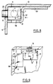
- FIGS. 1 to 4 Reference will first be made to FIGS. 1 to 4 with the aid of which the operation of the system allowing the articulated mounting of a panel of the cabinet will be explained.
- FIG. 1 we see the upper left interior corner of a panel 1 of a side wall of a cabinet.
- This panel can for example be the panel 1 which will be articulated around the vertical axis 3 on the chassis of a cabinet marked as a whole 2 as illustrated in FIG. 10. It will be noted that in the illustrated illustration the panel being shown from the inside the axis of the joint 3 is located on the right when looking at the panel from the outside as shown in Figure 10. In other words the orientations are reversed between Figure 1 and Figure 10 .
- a part 5 which in the example illustrated has a rectangular section and more specifically square.
- This part 5 is intended to be mounted as a slide which can move in translation parallel to the axis 3, that is to say at the vetical edge 12 of the panel 1 while being guided in a housing 20 formed between the profile of internal angle of the panel 1 constituted by the internal face of the rim 12 and the internal face 13 of the wall of the panel, and a square piece 6 fixed, for example glued or welded to the internal wall 13 of the panel 1.
- the square part has a section which is substantially in the form of a staircase with two parts 61, 62 at 90 ° closing on this side the housing 20 and a third part 63 for fixing to the wall 13.
- an opening 64 for the passage of a screw 21 which is screwed into a through hole 51 of the slide 5.
- the slide 5 is introduced in the orientation indicated in Figure 1 inside the passage 20 formed between the square part 6 and the internal angle of the panel formed by the adjacent walls 12, 13.
- the screw 21 passing through the slot 64 of the part 6 and screwing into the threaded orifice 55 of the slider 5 makes it possible to fix the slider 5 in position, so that the pivot 4 can either protrude as illustrated in FIG. 1, or be erased, it that is to say not projecting from the flange 11.
- this pivot 4 could obviously constitute a pivot for articulation of the panel allowing the opening of the panel as illustrated in Figure 10, provided of course that there are provided in the chassis of the corresponding housing for the articulation of the pivots 4.
- the hinge axis 3 containing the axis of the two opposite pivots 4.
- FIGS. 5 to 8 describe an operation of the lock system.
- Maintaining the lowered or raised position of the slide 5 in its housing 20 can advantageously be obtained by a clamping effect by means of a leaf spring 7 which will come to bear against the wall in staircase 62 of the square part 6 in coming to be anchored simply in the slide 5 for example in two slots 52, 53 which will house the suitably shaped ends 71, 72 of the blade 7.
- the panel can be mounted in articulation on its straight vertical edge around the axis 3, the panel being able to be locked on the cabinet by acting on the latches which will constitute the pivots 4 when will have controlled their projecting movement on the upper edge 11 and / or on the lower edge 15 of the panel 1.
- the corresponding angles of the housing cabinet are formed to receive the locking pivots 4.
- each panel will be treated in the same way, so that from a single type of slide piece 5 carrying a pivot 4 it will be possible to obtain the function of articulation or locking from any panel on any of its edges.
- the above described function can also be generalized to allow the indifferent articulation of the panels, not only on their horizontal edges but also on their vertical edges. In this case it will suffice to provide in each angle two symmetrical pieces 6, 6 ′ and the passages required in the panel edges for the pivots 4 and for the operating screw 22 of the lock.
- the panel can be opened for example by hinging just as well around the upper edge 11 as illustrated in FIG. 12 with a lock function provided at the bottom of the panel.
- the cabinet will include a hinged or tiltable door and three fixed side panels, that is to say actually locked by four lock functions as shown schematically by the crosses marked 25, 26, 27, 28 for the right side panel of the cabinet illustrated in Figure 10.
- the system also makes it possible, if a median articulation axis 29 of the panel is provided, for example, as illustrated in FIG. 13, to obtain a locking / unlocking function of this panel in one or more of its angles, for example on its two upper angles.
- the improvements of the invention apply very particularly to cabinets for the storage of electrical and electronic equipment considerably facilitating access to equipment by allowing in particular to intervene on all the lateral faces of the cabinet and also to make it also normally accessible by the desired face forming an access door opening to the left or to the right or even above or below depending on the arrangement of the cabinet and the premises.
- the design of the system makes it possible to avoid any protruding part beyond the external volume of the cabinet, the entire system remaining included inside the mounting frame.
Landscapes
- Engineering & Computer Science (AREA)
- Mechanical Engineering (AREA)
- Casings For Electric Apparatus (AREA)
Description
L'invention a pour objet un perfectionnement à des armoires et plus précisément à un système de montage de panneaux d'armoire permettant le verrouillage et/ou l'articulation à volonté des différents panneaux latéraux de l'armoire par rapport à son châssis.The subject of the invention is an improvement to cabinets and more specifically to a system for mounting cabinet panels allowing locking and / or articulation at will of the various side panels of the cabinet with respect to its chassis.
Selon le document DE-A-1 811 107, qui sert de base au préamble de la revendication 1, on connait déjà des machines comportant un système de montage de porte permettant l'articulation de la porte à gauche ou à droite avec un système de pivot formant verrou élastique ou articulation lorsque le verrou élastique est bloqué dans sa position sortie. En prévoyant quatre tels verrous en chacun des angles de la porte et en verrouillant en position sortie soit les verrous de gauche, soit les verrous de droite on obtient le résultat recherché.According to document DE-A-1 811 107, which serves as a basis for the preamble of
L'invention recherche une souplesse plus grande encore et a pour objet de permettre de traiter de la même manière chacun par exemple des quatre panneaux latéraux verticaux d'une armoire de section rectangulaire, chaque panneau pouvant être soit un panneau fixe, soit un panneau articulable sur l'un quelconque de ses bords.The invention seeks an even greater flexibility and has the object of making it possible to treat in the same way each one for example of the four vertical side panels of a cabinet of rectangular section, each panel being either a fixed panel or an articulated panel on any of its edges.
Avec un tel système, il apparaît que l'armoire constituée présente une souplesse d'emploi inconnue à ce jour, puisque chacun de ses panneaux latéraux pourra à volonté constituer soit un panneau fixe, soit un panneau articulé s'ouvrant à gauche ou à droite ou sur son bord supérieur en soulèvement ou sur son bord inférieur en abaissement, la disposition de l'ouverture pouvant être à chaque instant modifiée à volonté.With such a system, it appears that the built-in cabinet has a flexibility of use unknown to date, since each of its side panels can at will constitute either a fixed panel, or an articulated panel opening to the left or to the right or on its upper edge in raising or on its lower edge in lowering, the arrangement of the opening being able to be modified at any time at will.
Le système de l'invention permettant de telles fonctions comprend, associé à chaque angle du panneau, un pivot déplaçable en translation parallèlement à un côté du panneau dans un logement de guidage formé contre le profilé d'angle interne du panneau, entre ce profilé et une pièce en équerre fixée à l'intérieur de la surface du panneau, et verrouillable en position dans laquelle le pivot fait saillie sur son bord pour coopérer avec un logement correspondant formé dans le châssis recevant dans un angle de l'armoire et maintenant en position ledit pivot, et est caractérisé en ce que ledit pivot est porté par une pièce formant coulisseau se déplaçant avec ledit pivot dans ledit logement et ayant une section transversale carrée autorisant des engagements tournés de 90° l'un par rapport à l'autre de cette pièce dans son logement de guidage, selon le rôle recherché de pivot d'articulation dans lequel il est verrouillé en position saillante ou de verrou dans lequel il peut être manoeuvré soit en position saillante, soit en position retractée.The system of the invention enabling such functions comprises, associated with each corner of the panel, a pivot movable in translation parallel to a side of the panel in a guide housing formed against the internal corner profile of the panel, between this profile and a square piece fixed inside the surface of the panel, and lockable in position in which the pivot protrudes on its edge to cooperate with a corresponding housing formed in the chassis receiving in a corner of the cabinet and now in position said pivot, and is characterized in that said pivot is carried by a piece forming a slide moving with said pivot in said housing and having a square cross section allowing engagements turned by 90 ° relative to each other of this part in its guide housing, depending on the desired role of articulation pivot in which it is locked in the projecting position or lock in which it can be operated either in the projecting position or in the retracted position.
L'invention et sa mise en oeuvre apparaîtront plus clairement à l'aide de la description qui va suivre faite en référence aux dessins annexés illustrant un mode de réalisation. Dans ces dessins :
- La Figure 1 montre de façon schématique et en perspective l'angle d'un panneau pourvu des moyens de l'invention ;
- la Figure 2 est une vue semblable à celle de la Figure 1 mais dans laquelle le coulisseau porte-pivot a été retiré ;
- la Figure 3 montre le coulisseau porte-pivot ;
- la Figure 4 est une vue en coupe faite à plus grande échelle sensiblement dans le plan IV-IV de la Figure 1 montrant la position des pièces pour une utilisation en charnière du système ;
- la Figure 5 est une vue semblable à celle de la Figure 1 illustrant un autre angle du panneau dans lequel le système est en place dans la position de verrou ;
- la Figure 6 montre en vue perspective et schématique le coulisseau porte-pivot associé à sa lame ressort de blocage utilisable dans la position illustrée à la Figure 5;
- la Figure 7 montre le porte-coulisseau de la Figure 6 dans une position tournée de 90° autour de l'axe du pivot et dans le sens contraire de celui des aiguilles d'une montre ;
- La Figure 8 montre comme la Figure 4 une vue en coupe à plus grande échelle faite dans le plan VIII-VIII de la Figure 5 ;
- la Figure 9 montre un angle d'un panneau selon une variante équipée de moyens permettant l'articulation ou le verrouillage du panneau surl'une ou l'autre de ses tranches orthogonales ;
- les Figures 10, 11, 12 et 13 montrent de façon schématique quelques modes de montage et d'utilisation des panneaux articulables ou verrouillables conçus selon l'invention.
- Figure 1 shows schematically and in perspective the angle of a panel provided with the means of the invention;
- Figure 2 is a view similar to that of Figure 1 but in which the pivot slide has been removed;
- Figure 3 shows the pivot slide;
- Figure 4 is a sectional view made on a larger scale substantially in the plane IV-IV of Figure 1 showing the position of the parts for use in the hinge of the system;
- Figure 5 is a view similar to that of Figure 1 illustrating another angle of the panel in which the system is in place in the latch position;
- Figure 6 shows in perspective and schematic view the pivot carrier slide associated with its locking spring leaf usable in the position illustrated in Figure 5;
- Figure 7 shows the slide holder of Figure 6 in a position rotated 90 ° around the axis of the pivot and counterclockwise;
- Figure 8 shows like Figure 4 a sectional view on a larger scale made in the plane VIII-VIII of Figure 5;
- Figure 9 shows an angle of a panel according to a variant equipped with means allowing the articulation or locking of the panel on one or the other of its orthogonal sections;
- Figures 10, 11, 12 and 13 schematically show some modes of mounting and use of hinged or lockable panels designed according to the invention.
On se reportera tout d'abord aux Figures 1 à 4 à l'aide desquelles ont expliquera le fonctionnement du système permettant le montage en articulation d'un panneau de l'armoire.Reference will first be made to FIGS. 1 to 4 with the aid of which the operation of the system allowing the articulated mounting of a panel of the cabinet will be explained.
Comme illustré à la Figure 1 ont aperçoit l'angle intérieur supérieur gauche d'un panneau 1 d'une paroi latérale d'une armoire. Ce panneau peut être par exemple le panneau 1 qui s'articulera autour de l'axe vertical 3 sur le châssis d'une armoire repérée dans son ensemble 2 comme illustré à la Figure 10. On notera que dans la représentation illustrée le panneau étant montré de l'intérieur l'axe de l'articulation 3 est situé à droite lorsqu'on regarde le panneau de l'extérieur comme montré à la Figure 10. En d'autres termes les orientations sont inversées entre la Figure 1 et la Figure 10.As illustrated in Figure 1 we see the upper left interior corner of a
En se référant de nouveau à la Figure 1, on voit que le pivot 4 qui fait saillie au-dessus du rebord supérieur 11 du panneau 1 est porté par une pièce 5 qui dans l'exemple illustré a une section rectangulaire et plus spécifiquement carrée. Cette pièce 5 est destinée à être montée comme un coulisseau pouvant se déplacer en translation parallèlement à l'axe 3, c'est-à-dire au rebord vetical 12 du panneau 1 en étant guidé dans un logement 20 formé entre le profilé d'angle interne du panneau 1 constitué par la face intérieure du rebord 12 et la face interne 13 de la paroi du panneau, et une pièce en équerre 6 fixée, par exemple collée ou soudée sur la paroi interne 13 du panneau 1. De façon plus précise la pièce en équerre a une section sensiblement en marche d'escalier avec deux partie 61, 62 à 90° fermant de ce côté le logement 20 et une troisième partie 63 de fixation à la paroi 13. Dans la pièce d'équerre 6 est formée d'autre part une ouverture 64 pour le passage d'une vis 21 qui vient se visser dans un orifice traversant 51 du coulisseau 5.Referring again to Figure 1, we see that the pivot 4 which projects above the
Le fonctionnement du système apparaît clairement en relation de ce qui précède et notamment par examen comparatif des Figures 1 et 4.The functioning of the system appears clearly in relation to the above and in particular by examination comparison of Figures 1 and 4.
Le coulisseau 5 est introduit selon l'orientation indiquée à la Figure 1 à l'intérieur du passage 20 formé entre la pièce en équerre 6 et l'angle interne du panneau formé par les parois adjacentes 12, 13. La vis 21 traversant la fente 64 de la pièce 6 et se vissant dans l'orifice fileté 55 du coulisseau 5 permet de fixer en position le coulisseau 5, de telle sorte que le pivot 4 pourra soit faire saillie comme illustré à la Figure 1, soit être effacé, c'est-à-dire ne faisant pas saillie sur le rebord 11. Dans la position illustrée où le pivot 4 fait saillie au-dessus du rebord 11 du panneau, ce pivot 4 pourra évidemment constituer un pivot d'articulation du panneau permettant l'ouverture du panneau comme illustré à la Figure 10, à condition bien entendu que soient prévus dans le châssis de l'armoire les logements correspondants pour l'articulation des pivots 4. Bien entendu ce qui a été décrit pour l'angle supérieur du panneau est également prévu sur l'angle inférieur, l'axe d'articulation 3 contenant l'axe des deux pivots 4 opposés.The
On se reportera maintenant aux Figures 5 à 8 pour décrire un fonctionnement du système en verrou.Reference will now be made to FIGS. 5 to 8 to describe an operation of the lock system.
On retrouve tout d'abord, de façon générale les mêmes pièces que celles décrites aux Figures précédentes. En particulier on retrouve le coulisseau 5 avec son pivot 4 pouvant être positionné entre la pièce d'équerre 6 et l'angle correspondant du panneau. Dans l'exemple illustré à la Figure 5, on a supposé qu'il s'agissait de la même paroi de panneau que celle de la figure 1 mais de l'angle opposé, c'est-à-dire que l'on retrouve la bordure supérieure 11 du panneau comportant la paroi de fond 13 et la bordure verticale 14 symétrique et opposée à la bordure verticale 12 visible à la Figure 1. En d'autres termes sur la Figure 10, le bord 14 se trouve à gauche (à droite sur la Figure 5) à l'opposé du bord 12.First of all, we generally find the same parts as those described in the previous Figures. In particular, there is the
Par rapport à la position de montage du coulisseau illustrée à la Figure 1, le coulisseau de la Figure 5 a été tourné de 90° dans le sens inverse de rotation des aiguilles d'une montre, de sorte que l'alaisage fileté 51 qu'il présente va se trouver dirigé perpendiculairement à la tranche 14 du panneau, et non pas à l'intérieur du panneau comme illustré à la Figure 1. Dans cette tranche 14 est prévue une ouverture 15 qui permettra après introduction du coulisseau 5 dans son logement 20 d'introduire une vis 22 sans tête qui traversera l'ouverture 15 et viendra se visser dans l'alaisage fileté 51 du coulisseau. On comprend que de cette façon, il va être possible de manoeuvrer depuis l'extérieur de l'armoire le pivot 4 pour le soulever dans la position illustrée à la figure 5 ou au contraire l'abaisser et l'effacer pour qu'il ne fasse plus saillie sur le rebord 11 du panneau.Compared to the mounting position of the slide illustrated in Figure 1, the slide of Figure 5 has been rotated 90 ° in the opposite direction of rotation of the clockwise, so that the
Le maintien en position abaissée ou soulevée du coulisseau 5 dans son logement 20 peut être obtenu avantageusement par un effet de serrage au moyen d'une lame ressort 7 qui viendra porter contre la paroi en marche d'escalier 62 de la pièce en équerre 6 en venant s'ancrer simplement dans le coulisseau 5 par exemple dans deux fentes 52, 53 qui logeront les extrémités convenablement conformées 71, 72 de la lame 7.Maintaining the lowered or raised position of the
Dans la réalisation ainsi illustrée, il apparaît que le panneau pourra être monté en articulation sur son bord vertical droit autour de l'axe 3, le panneau pouvant se verrouiller sur l'armoire en agissant sur les verrous que constitueront les pivots 4 lorsqu'on aura commandé leur mouvement en saillie sur la tranche supérieure 11 et/ou sur la tranche inférieure 15 du panneau 1. Bien entendu sont formés dans les angles correspondants de l'armoire des logements pour recevoir les pivots 4 de verrouillage.In the embodiment thus illustrated, it appears that the panel can be mounted in articulation on its straight vertical edge around the
Et bien entendu la construction peut être immédiatement inversée en positionnant l'axe d'articulation 3 non pas à droite comme illustré à la Figure 10 mais à gauche comme illustré à la Figure 11 en inversant les fonctions d'axes formant pivot et d'axes formant verrou (verrouillage/déverrouillage). Et l'on notera que ce qui a été décrit pour un panneau de l'armoire est valable pour les quatre panneaux, de sorte que l'armoire peut indifféremment avoir une fonction de porte sur l'un quelconque de ses côtés voire sur plusieurs de ses côtés.And of course the construction can be immediately reversed by positioning the
On notera que de préférence tous les angles de chaque panneau seront traités de la même façon, de sorte que à partir d'un seul type de pièce coulisseau 5 portant un pivot 4 il sera possible d'obtenir la fonction d'articulation ou de verrouillage de n'importe quel panneau sur n'importe laquelle de ses tranches.It will be noted that preferably all the angles of each panel will be treated in the same way, so that from a single type of
Comme illustré à la Figure 9, la fonction ci-dessus décrite peut être généralisée également pour permettre l'articulation indifférente des panneaux, non seulement sur leurs tranches horizontales mais également sur leurs tranches verticales. Dans ce cas il suffira de prévoir dans chaque angle deux pièces symétriques 6, 6′ et les passages requis dans les tranches de panneaux pour les pivots 4 et pour la vis de manoeuvre 22 du verrou.As illustrated in Figure 9, the above described function can also be generalized to allow the indifferent articulation of the panels, not only on their horizontal edges but also on their vertical edges. In this case it will suffice to provide in each angle two
Ainsi le panneau pourra s'ouvrir par exemple en s'articulant tout aussi bien autour de la tranche supérieure 11 comme illustré à la Figure 12 avec une fonction de verrou prévue dans le bas du panneau. Habituellement l'amoire comprendra une porte articulable ou basculable et trois panneaux latéraux fixes, c'est-à-dire en fait verrouillés par quatre fonctions de verrou comme schématisé par les croix repérées 25, 26, 27, 28 pour le panneau latéral droit de l'armoire illustré à la Figure 10.Thus the panel can be opened for example by hinging just as well around the
Le système permet également si l'on prévoit par exemple un axe d'articulation 29 médian du panneau comme illustré à la Figure 13 d'obtenir une fonction de verrouillage/déverrouillage de ce panneau dans un ou plusieurs de ses angles, par exemple sur ses deux angles supérieurs.The system also makes it possible, if a
Les perfectionnements de l'invention s'appliquent tout particulièrement aux armoires pour le rangement d'appareillage électrique et électronique facilitant considérablement l'accès aux appareillages en permettant en particulier d'intervenir sur toutes les faces latérales de l'armoire et de la rendre également normalement accessible par la face souhaitée formant porte d'accès ouvrant à gauche ou à droite voire en haut ou en bas selon la disposition de l'armoire et des locaux. En outre la conception du système permet d'éviter toute pièce en saillie au-delà du volume extérieur de l'armoire, l'ensemble du système restant compris à l'intérieur du châssis de montage.The improvements of the invention apply very particularly to cabinets for the storage of electrical and electronic equipment considerably facilitating access to equipment by allowing in particular to intervene on all the lateral faces of the cabinet and also to make it also normally accessible by the desired face forming an access door opening to the left or to the right or even above or below depending on the arrangement of the cabinet and the premises. In addition, the design of the system makes it possible to avoid any protruding part beyond the external volume of the cabinet, the entire system remaining included inside the mounting frame.
Claims (5)
- System for assembling a cabinet panel enabling the panels to be locked and/or hinged relative to the framework or body of the cabinet comprising, associated with each corner of the panel (1), a pivot (4) which can be moved in translation parallel to one side of the panel in a guide housing (20) formed against the internal corner profiled section of the panel, between this profiled section and a right-angled part (6) secured to the interior of the panel surface (13), and which can be locked in a position in which the pivot (4) projects over its edge (11) so as to cooperate with a corresponding housing formed in the framework accommodating the said pivot in a corner of the cabinet and holding it in position, characterised in that the said pivot (4) is supported by a part forming a slide (5) which moves with the said pivot (4) in the said housing (20) and has a square cross-section enabling this part to locate in its guide housing (20) at positions rotated through 90° relative to one another, depending on whether the desired aim of the pivot is to act as a hinge in which it is locked in the projecting position or as a lock in which it can be manoeuvred either in a projecting position or in a retracted position.
- System according to Claim 1, characterised in that the said right-angled part (6) has a section (61, 62, 63) which is substantially in the form of a staircase.
- System according to either of the preceding claims, characterised in that, in order to maintain the pivot (4) in position for its function of articulating the panel (1), there is formed in the said pivot-carrier part forming a slide (5) a threaded aperture (51) which, via a gap (64) formed in a wall of the said right-angled part (6), accommodates a screw (21) for locking the said slide.
- System according to any one of the preceding claims, characterised in that an access opening (15) enabling the slide (5) to be displaced is formed in the edge wall (14) of the panel (1) in order to lock or unlock the pivot (4) for the function of locking/unlocking the panel (1).
- System according to Claim 4, characterised in that the slide (5) is held in position by resilient means such as a spring blade (7) acting between the said slide and the wall of its guide housing (20).
Applications Claiming Priority (2)
| Application Number | Priority Date | Filing Date | Title |
|---|---|---|---|
| FR8811732 | 1988-09-08 | ||
| FR8811732A FR2636104B1 (en) | 1988-09-08 | 1988-09-08 | PANEL CABINETS THAT CAN LOCK OR ARTICULATE ALONG ITS SIDES |
Publications (2)
| Publication Number | Publication Date |
|---|---|
| EP0358564A1 EP0358564A1 (en) | 1990-03-14 |
| EP0358564B1 true EP0358564B1 (en) | 1993-12-15 |
Family
ID=9369816
Family Applications (1)
| Application Number | Title | Priority Date | Filing Date |
|---|---|---|---|
| EP19890402414 Expired - Lifetime EP0358564B1 (en) | 1988-09-08 | 1989-09-05 | Cabinet made of panels lockable or hingeable along their sides |
Country Status (3)
| Country | Link |
|---|---|
| EP (1) | EP0358564B1 (en) |
| DE (1) | DE68911437T2 (en) |
| FR (1) | FR2636104B1 (en) |
Families Citing this family (3)
| Publication number | Priority date | Publication date | Assignee | Title |
|---|---|---|---|---|
| DE19811713C2 (en) * | 1998-03-18 | 2003-01-09 | Rittal Gmbh & Co Kg | switch cabinet |
| FR2883902B1 (en) * | 2005-04-05 | 2011-03-18 | Lamberet Const Isothermes | DEVICE FOR JOINING AN OPENING ON A STRUCTURE, SUCH AS AN ISOTHERMAL CONTAINER DOOR |
| GB2592343B (en) * | 2019-12-12 | 2023-07-05 | Hawes Gary | Security door for a cupboard |
Family Cites Families (3)
| Publication number | Priority date | Publication date | Assignee | Title |
|---|---|---|---|---|
| DE1811107A1 (en) * | 1968-11-22 | 1970-06-04 | Siemens Elektrogeraete Gmbh | Hinged door for drum washing machines that can be loaded from the front or other household machines |
| FR2305630A2 (en) * | 1971-06-23 | 1976-10-22 | Vinco Mt | Frame for metal furniture - having panels with stepped edged abutting square section uprights |
| ES229279Y (en) * | 1977-06-14 | 1978-02-01 | IMPROVED FLOW BOX. |
-
1988
- 1988-09-08 FR FR8811732A patent/FR2636104B1/en not_active Expired - Fee Related
-
1989
- 1989-09-05 DE DE1989611437 patent/DE68911437T2/en not_active Expired - Fee Related
- 1989-09-05 EP EP19890402414 patent/EP0358564B1/en not_active Expired - Lifetime
Also Published As
| Publication number | Publication date |
|---|---|
| DE68911437T2 (en) | 1994-05-19 |
| EP0358564A1 (en) | 1990-03-14 |
| DE68911437D1 (en) | 1994-01-27 |
| FR2636104B1 (en) | 1990-12-14 |
| FR2636104A1 (en) | 1990-03-09 |
Similar Documents
| Publication | Publication Date | Title |
|---|---|---|
| FR2948716A3 (en) | Full hiding hinge used for triaxial adjustment of components of e.g. door, has movable structure guided along horizontal axis by eccentric device accessed from opening side of storage portion when hinge exists in open position | |
| FR2666618A1 (en) | Articulated friction support and window comprising it | |
| EP0493225A1 (en) | Pivoting side door for motor vehicle | |
| EP0358564B1 (en) | Cabinet made of panels lockable or hingeable along their sides | |
| EP0347352B1 (en) | Fitting or a pivoting and tiltable wing of a door, window or the like with a sash which partially covers the window frame | |
| EP0219589B1 (en) | Folding door | |
| FR2829792A3 (en) | Adjustable concealed hinge has two sections enclosed in surrounding frame when door is closed | |
| FR2758585A1 (en) | CABINET LATCH | |
| EP0337886A1 (en) | Theft protection device for doors of vehicles or containers | |
| EP1770236B1 (en) | Sliding door assembly and corresponding truck | |
| FR2843606A1 (en) | Automobile hatchback door comprises vertical articulation and locking fingers located on lateral edges and horizontal articulation and locking fingers on transverse edge allowing disengagement of door from rest of vehicle by means of handle | |
| FR2723136A1 (en) | Safety hinge for door or window | |
| FR2672482A1 (en) | Display cabinet | |
| FR2597916A1 (en) | DEVICE FOR MOBILE ASSOCIATION OF AT LEAST ONE OPENING ELEMENT ON A DORMANT, AN OPENING DEVICE THAT CAN BE ASSOCIATED WITH A DORMANT BY SUCH A DEVICE, AND FITTING ELEMENT, PARTICULARLY FURNISHED WORKSHOP COMPRISING AT LEAST ONE SUCH DEVICE | |
| FR2526530A1 (en) | FRIDGE | |
| FR2793754A1 (en) | Hatchback for car has inner and outer panels, and articulation system restraining interference between bumper and outer panel when hatchback is opened | |
| EP0159271A2 (en) | Lock for a slide fastener | |
| EP0769602B1 (en) | Hinge for a door, window or the like | |
| FR2627798A1 (en) | SWING WINDOW WITH THREE OPENING MODES | |
| FR3033480A1 (en) | SWIVEL DRAWER SYSTEM AND FURNITURE EQUIPPED WITH SUCH A SYSTEM | |
| EP1053899A1 (en) | Tailgate for motor vehicle | |
| FR2814120A1 (en) | OPENING VEHICLE | |
| FR2777315A1 (en) | Container with opening hinged and sliding panel | |
| FR3155251A3 (en) | Electromagnetic lock device for double or single sliding door and double or single sliding door equipped with such an electromagnetic lock device | |
| EP0600785B1 (en) | Enclosure, with lock mechanism, for pay telephone |
Legal Events
| Date | Code | Title | Description |
|---|---|---|---|
| PUAI | Public reference made under article 153(3) epc to a published international application that has entered the european phase |
Free format text: ORIGINAL CODE: 0009012 |
|
| AK | Designated contracting states |
Kind code of ref document: A1 Designated state(s): DE GB IT |
|
| 17P | Request for examination filed |
Effective date: 19900619 |
|
| 17Q | First examination report despatched |
Effective date: 19920122 |
|
| GRAA | (expected) grant |
Free format text: ORIGINAL CODE: 0009210 |
|
| AK | Designated contracting states |
Kind code of ref document: B1 Designated state(s): DE GB IT |
|
| PG25 | Lapsed in a contracting state [announced via postgrant information from national office to epo] |
Ref country code: GB Effective date: 19931215 Ref country code: IT Free format text: LAPSE BECAUSE OF FAILURE TO SUBMIT A TRANSLATION OF THE DESCRIPTION OR TO PAY THE FEE WITHIN THE PRE;WARNING: LAPSES OF ITALIAN PATENTS WITH EFFECTIVE DATE BEFORE 2007 MAY HAVE OCCURRED AT ANY TIME BEFORE 2007. THE CORRECT EFFECTIVE DATE MAY BE DIFFERENT FROM THE ONE RECORDED.SCRIBED TIME-LIMIT Effective date: 19931215 |
|
| REF | Corresponds to: |
Ref document number: 68911437 Country of ref document: DE Date of ref document: 19940127 |
|
| GBV | Gb: ep patent (uk) treated as always having been void in accordance with gb section 77(7)/1977 [no translation filed] |
Effective date: 19931215 |
|
| PLBE | No opposition filed within time limit |
Free format text: ORIGINAL CODE: 0009261 |
|
| STAA | Information on the status of an ep patent application or granted ep patent |
Free format text: STATUS: NO OPPOSITION FILED WITHIN TIME LIMIT |
|
| 26N | No opposition filed | ||
| PGFP | Annual fee paid to national office [announced via postgrant information from national office to epo] |
Ref country code: DE Payment date: 20041130 Year of fee payment: 16 |
|
| PG25 | Lapsed in a contracting state [announced via postgrant information from national office to epo] |
Ref country code: DE Free format text: LAPSE BECAUSE OF NON-PAYMENT OF DUE FEES Effective date: 20060401 |