EP0358167A2 - Drehmoment-Regelsystem für einen Leistungsprüfstand von Verbrennungsmotoren - Google Patents
Drehmoment-Regelsystem für einen Leistungsprüfstand von Verbrennungsmotoren Download PDFInfo
- Publication number
- EP0358167A2 EP0358167A2 EP89116374A EP89116374A EP0358167A2 EP 0358167 A2 EP0358167 A2 EP 0358167A2 EP 89116374 A EP89116374 A EP 89116374A EP 89116374 A EP89116374 A EP 89116374A EP 0358167 A2 EP0358167 A2 EP 0358167A2
- Authority
- EP
- European Patent Office
- Prior art keywords
- torque
- rotor
- engine
- oscillating
- signal
- Prior art date
- Legal status (The legal status is an assumption and is not a legal conclusion. Google has not performed a legal analysis and makes no representation as to the accuracy of the status listed.)
- Granted
Links
- 238000011056 performance test Methods 0.000 title claims abstract description 29
- 238000002485 combustion reaction Methods 0.000 title claims abstract description 24
- 238000001514 detection method Methods 0.000 claims abstract description 17
- 238000012544 monitoring process Methods 0.000 claims abstract description 16
- 230000001133 acceleration Effects 0.000 claims description 52
- 230000004069 differentiation Effects 0.000 claims description 4
- 230000004044 response Effects 0.000 abstract description 6
- 230000008878 coupling Effects 0.000 description 10
- 238000010168 coupling process Methods 0.000 description 10
- 238000005859 coupling reaction Methods 0.000 description 10
- 238000012360 testing method Methods 0.000 description 5
- 238000000034 method Methods 0.000 description 4
- 230000003139 buffering effect Effects 0.000 description 3
- 230000003247 decreasing effect Effects 0.000 description 3
- 238000010586 diagram Methods 0.000 description 3
- 230000004043 responsiveness Effects 0.000 description 3
- 230000006835 compression Effects 0.000 description 2
- 238000007906 compression Methods 0.000 description 2
- 238000004880 explosion Methods 0.000 description 2
- 230000008569 process Effects 0.000 description 2
- 230000001052 transient effect Effects 0.000 description 2
- 230000005540 biological transmission Effects 0.000 description 1
- 238000007796 conventional method Methods 0.000 description 1
- 230000006866 deterioration Effects 0.000 description 1
- 239000003344 environmental pollutant Substances 0.000 description 1
- 238000012986 modification Methods 0.000 description 1
- 230000004048 modification Effects 0.000 description 1
- 231100000719 pollutant Toxicity 0.000 description 1
- 238000012552 review Methods 0.000 description 1
- 238000010998 test method Methods 0.000 description 1
Images


Classifications
-
- G—PHYSICS
- G01—MEASURING; TESTING
- G01M—TESTING STATIC OR DYNAMIC BALANCE OF MACHINES OR STRUCTURES; TESTING OF STRUCTURES OR APPARATUS, NOT OTHERWISE PROVIDED FOR
- G01M15/00—Testing of engines
-
- G—PHYSICS
- G01—MEASURING; TESTING
- G01M—TESTING STATIC OR DYNAMIC BALANCE OF MACHINES OR STRUCTURES; TESTING OF STRUCTURES OR APPARATUS, NOT OTHERWISE PROVIDED FOR
- G01M15/00—Testing of engines
- G01M15/04—Testing internal-combustion engines
- G01M15/042—Testing internal-combustion engines by monitoring a single specific parameter not covered by groups G01M15/06 - G01M15/12
- G01M15/044—Testing internal-combustion engines by monitoring a single specific parameter not covered by groups G01M15/06 - G01M15/12 by monitoring power, e.g. by operating the engine with one of the ignitions interrupted; by using acceleration tests
-
- F—MECHANICAL ENGINEERING; LIGHTING; HEATING; WEAPONS; BLASTING
- F02—COMBUSTION ENGINES; HOT-GAS OR COMBUSTION-PRODUCT ENGINE PLANTS
- F02B—INTERNAL-COMBUSTION PISTON ENGINES; COMBUSTION ENGINES IN GENERAL
- F02B3/00—Engines characterised by air compression and subsequent fuel addition
- F02B3/06—Engines characterised by air compression and subsequent fuel addition with compression ignition
Definitions
- the present invention relates to a torque control system which is optimally adapted for use in an engine performance test machine including an oscillating type electric dynamometer so as to make an engine performance test for internal combustion engines under a predetermined operating mode wherein the engine revolution and the output torque of the engine are changed in accordance with a predetermined test pattern.
- an oscillating type electric dynamometer In an engine performance test machine for internal combustion engines, an oscillating type electric dynamometer is traditionally used.
- the rotor shaft of the electric dynamometer is connected through a coupling device to the rotating member of the engine, which includes a crankshaft and a flywheel.
- a buffering device such as a shaft having a rubber damper is usually provided between the rotating member and the coupling device so as to prevent damage in the coupling device due to torque fluctuations generated by the engine.
- a clutch plate having torsional characteristics as shown in Fig. 3 is often provided between the rotating member of the engine and the coupling device.
- the torque fluctuation of diesel engines is greater than gasoline engines.
- both the buffering device and the clutch plate are generally used.
- engine performance such as output torque
- the mean engine torque is preponderantly detected and measured by the dynamometer.
- the component of engine torque fluctuation is not important and is not detected.
- the component of engine torque fluctuation is actually absorbed as an oscillating energy relative to the oscillating member which has a relatively large axial moment of inertia and which is disposed around the rotor of the dynamometer such that the oscillating member is oscillatably supported through bearings in a conventional method.
- the engine torque is continuously detectable by the torquemeter and the engine revolutions are continuously detected by the pickup serving as a pulse generator for pulse signals representative of an engine revolution.
- the engine revolutions and the engine torque may be precisely measured and/or controlled.
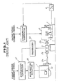
- a rotating member of an internal combustion engine 1 is connected through a connecting shaft, such as a drive shaft 2a and a coupling 3b to an input shaft of a torquemeter 3.
- the output shaft of the torquemeter 3 is connected through a coupling 2b to the rotor shaft of an oscillating type electric dynamometer 2.
- the torquemeter 3 outputs a signal representative of shaft torsion being essentially proportional to the output torque generated by the engine 1.
- the torsion signal from the torquemeter 3 is processed into the engine torque signal by a transducer 30.
- the engine torque signal is output from the transducer 30 to an accelerator controller 17, and is compared with a preset engine torque command signal representative of a preset engine torque.
- the accelerator controller 17 After comparing the preset torque command signal and the detected engine torque signal, the accelerator controller 17 outputs a signal representative of the difference between the two torque signals to the accelerator actuator 18.
- the accelerator actuator 18 adjusts the angular position of an accelerator 1a.
- the output torque of the engine 1 may be set to a predetermined value.
- the engine revolution is detected by a pickup 7 which is disposed in the vicinity of one end of the rotor shaft of the dynamometer 2.
- the pickup 7 outputs a pulse signal representative of the revolution of the rotor shaft to a frequency/voltage transducer 8, whereby the pulse signal from the pickup 7 is processed into an analog signal representative of an engine revolution.
- the engine revolution signal is output from the frequency/voltage transducer 8 to a dynamometer controller 9, and is compared with a preset engine revolution command signal representative of a preset engine revolution.
- the dynamometer controller 9 outputs a signal representative of the difference between the two revolution signals to the dynamometer 2.
- the load relative to the rotor of the dynamometer 2 is adjusted and as a result the revolution of the rotor is adjusted. That is, the engine revolution is set to a predetermined engine revolution.
- the above mentioned preset engine torque and engine revolution command signals are output via a preset value setting circuit (not shown) to the two controllers 17 and 9, respectively.
- a torsional vibration system shown in Fig. 2 is constructed.
- a rotating engine member having an axial moment of inertia I E connected through a clutch plate C, a drive shaft P including a rubber damper, a coupling C1, a torquemeter TM, and a coupling C2 to a rotor of the dynamometer having an axial moment of inertia I D , in that order. Therefore, in the conventional engine performance test machine constructed with the above mentioned torsional vibration system, torque fluctuations occur due to the torsional vibration system itself as well as torque fluctuation generated by the engine.
- a four-cycle diesel engine four strokes are utilized, namely an intake stroke, a compression stroke, an explosion stroke, and an exhaust stroke, fluctuation in torque generated by the engine occurs due to the compression stroke wherein the output torque is decreased and the explosion stroke wherein the output torque is increased.
- the frequency of the torque fluctuation is 20 Hz or more, when the engine is running at an idling speed, for example 600 r.p.m.
- the frequency of the torque fluctuation is 22.5 Hz or more, when the engine is running at idling speed, for example 450 r.p.m.
- the response frequency applicable for the engine torque control is 2 Hz or less. Therefore, such a relatively high frequency torque fluctuation generated by the engine may be filtered by means of a low-pass filter.
- engine torque control can be executed by engine torque detected through the torquemeter, not including the component of torque fluctuation occurring in the engine.
- the frequency of the torque fluctuation corresponds to the torsional vibration frequency of the torsional vibration system shown in Fig. 2. If the torsional rigidity of the connecting device is set to a relatively high value, there is a possibility that the torsional vibration frequency of the torsional vibration system will become equal to the frequency of the torque fluctuation occurring in the engine. When the two frequencies become equal to each other, resonance relative to the connecting device occurs through torque fluctuation of the engine, thereby resulting in damage to the connecting device. For this reason, the torsional rigidity of the connecting device is generally set to a relatively low value.
- the connecting device is comprised of the clutch plate of a manual transmission including a plurality of torsion springs and/or a drive shaft including a rubber damper.
- the frequency of the torsional vibration system is set to a relatively low frequency, for example 5 Hz or less.
- the frequency of the torsional vibration system changes depending on the torsional characteristics of the clutch plate shown in Fig. 3.
- Fig 3 As clearly seen in Fig 3, as the absolute value of the engine torque is increased, the torsional angle of the clutch plate is increased, that is the torsional rigidity of the clutch plate is increased. Conversely, as the absolute value of the engine torque is decreased, the torsional rigidity of the clutch plate is decreased.
- the torsional vibration frequency of the torsional vibration system changes within a range of relatively low frequencies, for example 5 Hz or less. Since the torsional vibration frequency range of the torsional vibration system is in close proximity to the response frequency, for example 2 Hz, required for the torque control, the component of torque fluctuation generated due to the torsional vibration system cannot be filtered by the low-pass filter. As a result, the above mentioned component of the torque fluctuation generated by the torsional vibration system deteriorates the torque control accuracy.
- the accelerator 18 can be controlled by the controller 17 in response to the torque fluctuation due to the torsional vibration system as well as the actual output torque fluctuation.
- the response frequency may be lowered to 0.5 Hz or less.
- such an extremely low response frequency results in a low responsiveness of the accelerator controller for torque control.
- an object of the present invention to provide an optimal torque control system having high responsiveness and high accuracy serving as an engine performance test machine for internal combustion engines.
- a torque control system for an engine performance test machine for internal combustion engines comprises an oscillating type electric dynamometer including a rotor and an oscillating member being oscillatably supported around the rotor, means for interconnecting the rotor shaft of the rotor and the rotating member of an internal combustion engine, means for monitoring oscillating torque of the oscillating member to generate a signal representative of the oscillating torque, means for generating a first torque signal representative of a first torque occurring at the rotor, means for generating a second torque signal representative of a second torque occurring at the rotating member of the engine, means for generating a detection signal representative of the sum of the oscillating torque signal, and the first and second torque signals, and a controller for controlling the torque generated by the engine according to a control value derived by comparing the detection signal with the preset torque command signal for the engine, the controller generating a control signal representative of the control value.
- the first torque generating means also comprises means for deriving the angular acceleration of the rotor to generate a signal representative of the angular acceleration of the rotor and means for multiplying the signal from the rotor angular acceleration deriving means by a moment of inertia of the rotor
- the second torque generating means also comprises means for deriving angular acceleration of the rotating member of the engine to generate a signal representative of the angular acceleration of the rotating member and means for multiplying the signal from the rotating member angular acceleration deriving means by a moment of inertia of the rotating member.
- the means for deriving the angular acceleration may comprise an accelerometer added to the rotating member of the engine or added to the rotor of the dynamometer.
- a torque control system for an engine performance test machine for internal combustion engines comprises an oscillating type electric dynamometer including a rotor and an oscillating member being oscillatably supported around the rotor, means for interconnecting the rotor shaft of the rotor and the rotating member of an internal combustion engine, first means for monitoring oscillating torque of the oscillating member, the first means generating a signal representative of the oscillating torque, second means for monitoring angular speed of the rotor, the second means generating a signal representative of the angular speed of the rotor, third means for monitoring angular speed of the rotating member of the engine, the third means generating a signal representative of the angular speed of the rotating member, a first differentiator for differentiating the angular speed of the rotor to generate a signal representative of the angular acceleration of the rotor, a second differentiator for differentiating the angular speed of the rotating member to generate a signal representative of the angular acceleration of the rotor
- the first means may comprise an accelerometer added to the oscillating member.
- the second/third means comprises a pickup used for monitoring angular speed.
- the first/second torque generating means comprises a multiplier.
- the detection signal generating means comprises an adder.
- the control signal from the controller is output to an accelerator actuator through which the accelerator of the engine is set to a predetermined angular position.
- a torque control system for an engine performance test machine for internal combustion engines comprises an oscillating type electric dynamometer including a rotor and an oscillating member being oscillatably supported, around the rotor, means for interconnecting the rotor shaft of the rotor and the rotating member of an internal combustion engine, means for monitoring oscillating torque of the oscillating member to generate a signal representative of the oscillating torque, means for deriving angular acceleration of the rotor to generate a signal representative of the angular acceleration of the rotor, means for deriving angular acceleration of the rotating member of the engine to generate a signal representative of the angular acceleration of the rotating member, means for generating a first torque signal representative of a first torque occurring at the rotor by multiplying the signal from the rotor angular acceleration deriving means by a moment of inertia of the rotor, means for generating a second torque signal representative of a second torque occurring at the rotating member by multiplying
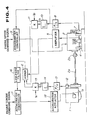
- the rotating member of the internal combustion engine 1 which includes a crankshaft and a flywheel is connected through a drive shaft 2a having a rubber damper and a coupling 2b to the rotor shaft of an oscillating type electric dynamometer 2.
- Reference numeral 4 denotes a load cell disposed between the base of the dynamometer and the previously described oscillating member so as to detect the oscillating torque of the oscillating member of the dynamometer 2.
- the oscillating torque is substantially equal to the component of the fluctuation in torque generated by the engine 1.
- the load cell 4 generates a signal representative of the oscillating torque.
- the signal from the load cell 4 is amplified through an amplifier 5 and thereafter is output to an adder 6 as an oscillating torque signal T L .
- a pickup 7 is provided in the vicinity of one end of the rotor shaft of the dynamometer 2 to detect the revolutions of the rotor of the dynamometer 2.
- the pickup 7 outputs a pulse signal representative of the revolution of the rotor shaft to a frequency/voltage transducer 8, and then the pulse signal from the pickup 7 is processed into an analog signal representative of the angular speed of the rotor of the dynamometer 2.
- the rotor angular speed signal ⁇ D is output from the frequency/voltage transducer 8 to a dynamometer controller 9, and is compared with a preset engine angular speed command signal representative of a preset engine angular speed.
- the dynamometer controller 9 After comparing the preset angular speed command signal and the detected rotor angular speed signal, the dynamometer controller 9 outputs a signal representative of the difference between the two angular speed signals to the dynamometer 2. As a result, the load relative to the rotor of the dynamometer 2 is adjusted and thus the angular speed of the rotor is adjusted. In this manner, engine revolution is set to a predetermined value.
- the rotor angular speed signal ⁇ D is also output to a differentiator 10. Thereafter, the differentiator 10 processes the rotor angular speed signal ⁇ D into an angular acceleration signal ⁇ D representative of an angular acceleration of the rotor.
- the angular acceleration signal ⁇ D is output from the differentiator 10 to a multiplier 11.
- the multiplier 11 multiplies the angular acceleration signal ⁇ D by an axial moment of inertia I D of the rotor of the dynamometer 2 and generates a first torque signal I D . ⁇ D representative of a torque component occurring at the moment of inertia I D .
- the first torque signal I D . ⁇ D is also output from the multiplier 11 to the adder 6.
- a pickup 12 is provided in the vicinity of the output end of the rotating member of the engine 1 to detect the revolution of the rotating member of the engine 1.
- the pickup 12 outputs a pulse signal representative of the revolution of rotating member to a frequency/voltage transducer 13, and then the pulse signal from the pickup 12 is processed into an analog signal representative of the angular speed of the rotating member.
- the rotating member angular speed signal ⁇ E is output from the frequency/voltage transducer 8 to a differentiator 14 which processes the rotating member angular speed signal ⁇ E into an angular acceleration signal ⁇ E representative of an angular acceleration of the rotating member.
- the angular acceleration signal ⁇ E is output from the differentiator 14 to a multiplier 15.
- the multiplier 15 multiplies the angular acceleration signal ⁇ E by an axial moment of inertia I E of the rotating member including the crankshaft and the flywheel and generates a second torque signal I E . ⁇ E representative of a torque component occurring at the moment of inertia I E . Thereafter, the second torque signal I E . ⁇ E is output from the multiplier 15 to an adder 6.
- the adder 6 receives the oscillating torque signal T L , and the first and second torque signals I D . ⁇ D and I E . ⁇ E , and adds the three torque signals.
- the adder 6 outputs a total torque signal (T L + I D . ⁇ D + I E . ⁇ E ) through a low-pass filter 16 to an accelerator controller 17.
- the sum (T L + I D . ⁇ D ) of the two torque signals T L and I D . ⁇ D is approximate to the engine torque signal detected by the torquemeter in accordance with the previously described conventional torque measuring method.
- the total torque signal (T L + I D . ⁇ D + I E . ⁇ E ) corresponds to the actual torque generated by the engine 1.
- the total torque signal also includes the torque component occurring at the moment of inertia I E .
- the accelerator controller 17 compares the filtered total torque signal and a preset engine torque command signal and generates a control signal representative of the difference between the above mentioned two torque signals to an accelerator actuator 18.
- the accelerator actuator 18 adjusts the angular position of an accelerator 1a.
- the output torque of the engine 1 is set to a predetermined value.
- torque control since the output torque of the engine is controlled by the actual detected torque as previously described, torque control may be precisely and quickly executed depending on the actual torque fluctuation of the engine, regardless of torque fluctuations due to the torsional vibration system comprising the engine, the connecting device, and the dynamometer.
- Fig. 5 shows the second embodiment of the torque control system according to the invention.
- the torque control system according to the second embodiment is optimally applied to an engine performance test machine operated in accordance with a test method wherein it is required that the output torque is controlled not by the actual torque generated by the engine but the engine torque transmitted through the drive shaft to the dynamometer. That is, the torque control system according to the second embodiment is effective in torque control performed in accordance with the engine torque as measured at the drive shaft.
- the second embodiment will be hereinbelow described in brief, because the elements used in the second embodiment are similar to the elements used in the first embodiment.
- the revolution of the rotor of the dynamometer 2 is detected by the pickup 7 and is processed through the frequency/voltage transducer 8, the differentiator 10, and the multiplier 11 in that order, and is fed to the adder 20 as a first torque signal I D . ⁇ D representative of a torque component occurring at the moment of inertia I D of the rotor of the dynamometer 2.
- the revolution of the rotating member of the engine is detected by the pickup 12 and is processed through the frequency/voltage transducer 13, the differentiator 14, and the multiplier 15 in that order, and is fed to the adder 20 as a second torque signal I E . ⁇ E representative of a torque component occurring at the moment of inertia I E of the rotating member of the engine.
- the adder 20 adds the first and second torque signals I D . ⁇ D and I E . ⁇ E and outputs a signal (I D . ⁇ D + I E . ⁇ E ) to a divider 21.
- the divider divides the signal from the adder 20 by the sum (I D + I E ) of the two moments of inertia I D and I E and outputs a signal (I D . ⁇ D + I E . ⁇ E )/ (I D + I E ) to a multiplier 22.
- the signal output from the divider 21 corresponds to a mean angular acceleration signal representative of the mean angular acceleration of the rotor of the dynamometer and the rotating member of the engine.
- the mean angular acceleration signal is fed through the multiplier 22 to an adder 23 as a torque signal I D .(I D . ⁇ D + I E . ⁇ E )/(I D + I E ), not including the torque component occurring at the moment of inertia of the rotating member of the engine.
- the adder 23 also receives the oscillating torque signal T L which was previously described in the first embodiment, supplied from the load cell 4 through the amplifier 5.
- the adder 23 adds the two torque signals output from the amplifier 5 and the multiplier 22 and generates a mean engine torque signal ⁇ T L + I D .(I D . ⁇ D + I E . ⁇ E )/(I D + I E ) ⁇ .
- the mean engine torque signal is filtered through the low-pass filter 16 and is fed to the accelerator controller 17 as a detected engine torque signal.
- the output torque of the engine is adjusted to a predetermined value by the accelerator controller 17.
- the torque control system according to the second embodiment may precisely control the output torque of the engine without a torquemeter.
- torque control is effected by the accelerator controller, while the speed control is operated by the dynamometer controller, the torque control may be operated by the dynamometer controller and the speed control may be operated by the accelerator controller.
- the moment of inertia of the rotor of the dynamometer and the moment of inertia of the rotating member of the engine are derived by the multipliers, a compensated moment of inertia which considers the moment of inertia of the connecting device may also be used for the previously described torque calculation.
- a load cell is provided to detect oscillating torque substantially equal to the component of torque fluctuation occurring in the engine. Since the load cell has elasticity, the vibration system is constructed by the load cell and the oscillating member of the dynamometer. For this reason, the performance of the torque control system is slightly lowered. Therefore, the oscillating torque may be monitored by an accelerometer added to the oscillating member to provide a torque control system with a higher accuracy.
- the torque control system for an engine performance test machine is adapted for internal combustion engines, the system may be applied to diesel engines having a relatively large torque fluctuation.
- each angular acceleration is derived such that the angular speed of the rotating section to be measured is detected by the pickup and thereafter the detected angular speed is differentiated by a differentiator
- the angular acceleration may be directly derived by an accelerometer.
Landscapes
- Physics & Mathematics (AREA)
- General Physics & Mathematics (AREA)
- Chemical & Material Sciences (AREA)
- Engineering & Computer Science (AREA)
- Combustion & Propulsion (AREA)
- Testing Of Engines (AREA)
- Feedback Control In General (AREA)
- Control Of Vehicle Engines Or Engines For Specific Uses (AREA)
- Electrical Control Of Air Or Fuel Supplied To Internal-Combustion Engine (AREA)
- Combined Controls Of Internal Combustion Engines (AREA)
Applications Claiming Priority (2)
| Application Number | Priority Date | Filing Date | Title |
|---|---|---|---|
| JP221582/88 | 1988-09-05 | ||
| JP63221582A JP2623758B2 (ja) | 1988-09-05 | 1988-09-05 | ディーゼルエンジンのトルク制御装置 |
Publications (3)
| Publication Number | Publication Date |
|---|---|
| EP0358167A2 true EP0358167A2 (de) | 1990-03-14 |
| EP0358167A3 EP0358167A3 (de) | 1991-09-25 |
| EP0358167B1 EP0358167B1 (de) | 1995-02-01 |
Family
ID=16769002
Family Applications (1)
| Application Number | Title | Priority Date | Filing Date |
|---|---|---|---|
| EP89116374A Expired - Lifetime EP0358167B1 (de) | 1988-09-05 | 1989-09-05 | Drehmoment-Regelsystem für einen Leistungsprüfstand von Verbrennungsmotoren |
Country Status (5)
| Country | Link |
|---|---|
| US (1) | US4995139A (de) |
| EP (1) | EP0358167B1 (de) |
| JP (1) | JP2623758B2 (de) |
| KR (1) | KR970003681B1 (de) |
| DE (1) | DE68920934T2 (de) |
Cited By (4)
| Publication number | Priority date | Publication date | Assignee | Title |
|---|---|---|---|---|
| EP0741286A3 (de) * | 1995-05-02 | 1997-05-02 | New Holland Italia Spa | Messung der Rotationsgeschwindigkeit und des Drehmomentes |
| EP2128591A3 (de) * | 2008-05-26 | 2016-04-27 | AVL List GmbH | Verfahren zur Überwachung von Leistungsprüfständen, sowie Leistungsprüfstand |
| US9366313B2 (en) | 2013-03-15 | 2016-06-14 | General Electric Company | Torsional resonance frequency adjustor |
| US9551398B2 (en) | 2013-03-15 | 2017-01-24 | General Electric Company | Torsional mode shifting |
Families Citing this family (21)
| Publication number | Priority date | Publication date | Assignee | Title |
|---|---|---|---|---|
| US5049768A (en) * | 1987-07-15 | 1991-09-17 | The Boeing Company | Reducing engine noise by active oscillatory torque control |
| CH676810A5 (de) * | 1988-09-27 | 1991-03-15 | Inst Litya Akademii Nauk Uk Ss | |
| JP2604036B2 (ja) * | 1989-06-09 | 1997-04-23 | 株式会社東芝 | エンジン試験制御装置 |
| JPH0315645A (ja) * | 1989-06-13 | 1991-01-24 | Hitachi Ltd | エンジン制御装置 |
| JP2542095B2 (ja) * | 1989-12-11 | 1996-10-09 | ジャトコ株式会社 | モ―タの過負荷監視装置 |
| US5140529A (en) * | 1990-08-14 | 1992-08-18 | Peifer Wilhelm M | Reverse torque preload spindle |
| US5553514A (en) * | 1994-06-06 | 1996-09-10 | Stahl International, Inc. | Active torsional vibration damper |
| AT350U1 (de) * | 1994-08-18 | 1995-08-25 | Avl Verbrennungskraft Messtech | Elektrische motorbremsvorrichtung |
| DE19650570A1 (de) * | 1996-12-06 | 1998-06-10 | Voith Turbo Kg | Verfahren zur Regelung des Schleppmomentes in einem dieselelektrischen Antriebssystem und Antriebssystem |
| US6039028A (en) * | 1999-01-14 | 2000-03-21 | Ford Global Technologies, Inc. | Active engine speed pulsation damping |
| JP3772721B2 (ja) * | 2001-10-11 | 2006-05-10 | 株式会社明電舎 | エンジンベンチシステムおよびエンジン特性の測定方法 |
| JP3775284B2 (ja) * | 2001-11-08 | 2006-05-17 | 株式会社明電舎 | エンジンベンチシステムおよびエンジン特性の測定方法 |
| US7194398B2 (en) * | 2002-03-13 | 2007-03-20 | Ford Global Technologies, Llc | Method and apparatus for designing and developing a vehicular damper |
| US6918287B2 (en) * | 2003-08-25 | 2005-07-19 | James M. Laws | Method and apparatus for measuring the acceleration of an engine |
| JP4591177B2 (ja) * | 2005-04-20 | 2010-12-01 | 株式会社明電舎 | エンジン試験装置 |
| AT7889U3 (de) * | 2005-06-15 | 2006-12-15 | Avl List Gmbh | Verfahren zur prüfung eines dynamischen drehmomenterzeugers und vorrichtung zur ermittlung des dynamischen verhaltens einer verbindungswelle |
| FR2959836B1 (fr) * | 2010-05-07 | 2012-06-01 | Messier Bugatti | Procede de gestion d'un mouvement de lacet d'un aeronef roulant au sol. |
| JP5830870B2 (ja) * | 2011-02-14 | 2015-12-09 | 株式会社明電舎 | 回転体速度/加速度の計測・制御装置 |
| AT509381B1 (de) * | 2011-05-09 | 2012-04-15 | Avl List Gmbh | Prüfstand für dynamische prüfaufgaben an verbrennungskraftmaschinen, sowie verfahren zum betreiben eines derartigen prüfstandes |
| JP5708704B2 (ja) | 2013-05-15 | 2015-04-30 | 株式会社明電舎 | エンジンベンチシステム |
| JP6044649B2 (ja) * | 2015-01-19 | 2016-12-14 | 株式会社明電舎 | ダイナモメータシステムの制御装置 |
Family Cites Families (4)
| Publication number | Priority date | Publication date | Assignee | Title |
|---|---|---|---|---|
| US3898875A (en) * | 1973-10-09 | 1975-08-12 | Whirlpool Co | Method and apparatus for testing electric motors |
| US3926043A (en) * | 1974-04-24 | 1975-12-16 | Lab Equipment Corp | Road simulator system with provision for engine degradation compensation |
| JPS5433401A (en) * | 1977-08-16 | 1979-03-12 | Meidensha Electric Mfg Co Ltd | Method of driving equivaent road simulation system |
| US4758967A (en) * | 1986-05-12 | 1988-07-19 | Ford Motor Company | Computer simulated inertia for motor vehicle powertrain testing |
-
1988
- 1988-09-05 JP JP63221582A patent/JP2623758B2/ja not_active Expired - Fee Related
-
1989
- 1989-09-05 KR KR1019890012801A patent/KR970003681B1/ko not_active Expired - Lifetime
- 1989-09-05 US US07/402,790 patent/US4995139A/en not_active Expired - Fee Related
- 1989-09-05 EP EP89116374A patent/EP0358167B1/de not_active Expired - Lifetime
- 1989-09-05 DE DE68920934T patent/DE68920934T2/de not_active Expired - Fee Related
Cited By (4)
| Publication number | Priority date | Publication date | Assignee | Title |
|---|---|---|---|---|
| EP0741286A3 (de) * | 1995-05-02 | 1997-05-02 | New Holland Italia Spa | Messung der Rotationsgeschwindigkeit und des Drehmomentes |
| EP2128591A3 (de) * | 2008-05-26 | 2016-04-27 | AVL List GmbH | Verfahren zur Überwachung von Leistungsprüfständen, sowie Leistungsprüfstand |
| US9366313B2 (en) | 2013-03-15 | 2016-06-14 | General Electric Company | Torsional resonance frequency adjustor |
| US9551398B2 (en) | 2013-03-15 | 2017-01-24 | General Electric Company | Torsional mode shifting |
Also Published As
| Publication number | Publication date |
|---|---|
| KR900005251A (ko) | 1990-04-13 |
| EP0358167A3 (de) | 1991-09-25 |
| EP0358167B1 (de) | 1995-02-01 |
| DE68920934D1 (de) | 1995-03-16 |
| JPH0270936A (ja) | 1990-03-09 |
| KR970003681B1 (ko) | 1997-03-21 |
| JP2623758B2 (ja) | 1997-06-25 |
| US4995139A (en) | 1991-02-26 |
| DE68920934T2 (de) | 1995-05-24 |
Similar Documents
| Publication | Publication Date | Title |
|---|---|---|
| EP0358167B1 (de) | Drehmoment-Regelsystem für einen Leistungsprüfstand von Verbrennungsmotoren | |
| US4922869A (en) | Torque controlling apparatus for internal combustion engine | |
| US4984988A (en) | Simulated engine characteristic control system | |
| US6820593B2 (en) | Regulation of true running for diesel engines | |
| US5056487A (en) | Torque control apparatus and method for internal combustion engines | |
| EP0924421B1 (de) | Kraftstoffeinspritz-Regelvorrichtung für eine Brennkraftmaschine | |
| US4982707A (en) | Automotive vehicle vibration control arrangement | |
| US7761224B2 (en) | Drive train | |
| US5546793A (en) | Process for determining gas-force transmitted torque to an internal-combustion engine crankshaft | |
| JP3294957B2 (ja) | 内燃機関の制御装置 | |
| US3800599A (en) | Surge sensor based on engine mount deflection | |
| US4550595A (en) | Torque measurement circuit and method | |
| CN114901532B (zh) | 用于控制混合动力传动系的方法 | |
| US5726352A (en) | Method of detecting misfires in a multicylinder internal combustion engine | |
| US5394742A (en) | Method for recognizing abnormal combustions in the cylinder of an internal-combustion engine | |
| JP4019709B2 (ja) | エンジンベンチシステム | |
| JP3226290B2 (ja) | 内燃機関のトルク制御装置 | |
| JPH01267327A (ja) | 内燃機関のトルク制御装置 | |
| EP1072778B1 (de) | Verfahren zur Regelung der Leerlaufdrehzahl einer Brennkraftmaschine | |
| JPH0798262A (ja) | ねじり加振試験機 | |
| JP2760806B2 (ja) | 内燃機関のトルク制御装置 | |
| Kadomukai et al. | Reducing vibration in idling vehicles by actively controlling electric machine torque | |
| von Thun | A new dynamic combustion engine test stand with real-time simulation of the vehicle drive line | |
| Iddum et al. | Performance of Virtual Torque Sensor for Heavy Duty Truck Applications | |
| SU1275236A1 (ru) | Устройство дл определени мощности двигател внутреннего сгорани |
Legal Events
| Date | Code | Title | Description |
|---|---|---|---|
| PUAI | Public reference made under article 153(3) epc to a published international application that has entered the european phase |
Free format text: ORIGINAL CODE: 0009012 |
|
| AK | Designated contracting states |
Kind code of ref document: A2 Designated state(s): DE FR GB IT |
|
| PUAL | Search report despatched |
Free format text: ORIGINAL CODE: 0009013 |
|
| AK | Designated contracting states |
Kind code of ref document: A3 Designated state(s): DE FR GB IT |
|
| 17P | Request for examination filed |
Effective date: 19911016 |
|
| 17Q | First examination report despatched |
Effective date: 19920928 |
|
| GRAA | (expected) grant |
Free format text: ORIGINAL CODE: 0009210 |
|
| AK | Designated contracting states |
Kind code of ref document: B1 Designated state(s): DE FR GB IT |
|
| REF | Corresponds to: |
Ref document number: 68920934 Country of ref document: DE Date of ref document: 19950316 |
|
| ITF | It: translation for a ep patent filed | ||
| ET | Fr: translation filed | ||
| PLBE | No opposition filed within time limit |
Free format text: ORIGINAL CODE: 0009261 |
|
| STAA | Information on the status of an ep patent application or granted ep patent |
Free format text: STATUS: NO OPPOSITION FILED WITHIN TIME LIMIT |
|
| 26N | No opposition filed | ||
| PGFP | Annual fee paid to national office [announced via postgrant information from national office to epo] |
Ref country code: DE Payment date: 19961029 Year of fee payment: 8 |
|
| PG25 | Lapsed in a contracting state [announced via postgrant information from national office to epo] |
Ref country code: DE Free format text: LAPSE BECAUSE OF NON-PAYMENT OF DUE FEES Effective date: 19980603 |
|
| PGFP | Annual fee paid to national office [announced via postgrant information from national office to epo] |
Ref country code: FR Payment date: 19980917 Year of fee payment: 10 |
|
| PG25 | Lapsed in a contracting state [announced via postgrant information from national office to epo] |
Ref country code: FR Free format text: LAPSE BECAUSE OF NON-PAYMENT OF DUE FEES Effective date: 20000531 |
|
| REG | Reference to a national code |
Ref country code: FR Ref legal event code: ST |
|
| PGFP | Annual fee paid to national office [announced via postgrant information from national office to epo] |
Ref country code: GB Payment date: 20010814 Year of fee payment: 13 |
|
| REG | Reference to a national code |
Ref country code: GB Ref legal event code: IF02 |
|
| PG25 | Lapsed in a contracting state [announced via postgrant information from national office to epo] |
Ref country code: GB Free format text: LAPSE BECAUSE OF NON-PAYMENT OF DUE FEES Effective date: 20020905 |
|
| GBPC | Gb: european patent ceased through non-payment of renewal fee |
Effective date: 20020905 |
|
| PG25 | Lapsed in a contracting state [announced via postgrant information from national office to epo] |
Ref country code: IT Free format text: LAPSE BECAUSE OF NON-PAYMENT OF DUE FEES Effective date: 20050905 |