EP0358133A2 - Magnetfeldkompensator für eine Kathodenstrahlröhre - Google Patents
Magnetfeldkompensator für eine Kathodenstrahlröhre Download PDFInfo
- Publication number
- EP0358133A2 EP0358133A2 EP89116221A EP89116221A EP0358133A2 EP 0358133 A2 EP0358133 A2 EP 0358133A2 EP 89116221 A EP89116221 A EP 89116221A EP 89116221 A EP89116221 A EP 89116221A EP 0358133 A2 EP0358133 A2 EP 0358133A2
- Authority
- EP
- European Patent Office
- Prior art keywords
- magnetic field
- neutralizing
- earth
- coils
- component
- Prior art date
- Legal status (The legal status is an assumption and is not a legal conclusion. Google has not performed a legal analysis and makes no representation as to the accuracy of the status listed.)
- Granted
Links
Images


Classifications
-
- H—ELECTRICITY
- H04—ELECTRIC COMMUNICATION TECHNIQUE
- H04N—PICTORIAL COMMUNICATION, e.g. TELEVISION
- H04N9/00—Details of colour television systems
- H04N9/12—Picture reproducers
- H04N9/16—Picture reproducers using cathode ray tubes
- H04N9/29—Picture reproducers using cathode ray tubes using demagnetisation or compensation of external magnetic fields
Definitions
- the invention relates to an automatic cancellation of external magnetic fields and, in particular, to apparatus for compensating for an external magnetic field affecting the operation of a cathode ray tube (CRT) display.
- CTR cathode ray tube
- the earth's magnetic field in the northern hemisphere is characterized by magnetic lines of force dipping downward and toward what is commonly referred to as the earth's north magnetic pole, but which by electromagnetic theory is actually a south magnetic pole.
- a vector H may be drawn to represent the direction and intensity of the earth's field.
- the vector H that is substantially uniform at any geographical location may be separated into vertical and horizontal components, H y and H h , respectively.
- H y and H h For the continental United States the horizontal intensity H h in the direction of the magnetic North varies from about .27 gauss in the southern parts to about .16 gauss in the northern parts.
- Color purity in a color television receiver tends to be adversely affected by the earth's magnetic field.
- An example of such a color television receiver is the shadow mask receiver.
- the CRT has three electron guns and an apertured mask through which the electron beams pass to impinge upon the screen, which has phosphor stripes thereon emissive of light of different colors.
- the electron beams be properly directed and properly convergent so that at each scanning instant when an elemental area of the color image is being reproduced, the electron beams will pass through the correct aperture of the mask and impinge on the proper phosphor stripe of the screen.
- a CRT having a large screen such as a 32-inch (81 cm) CRT, may be more sensitive to the earth's magnetic field than a CRT having a small screen. Greater sensitivity may exist for large screen CRT than for a smaller screen CRT because a given bending of the electron beam path caused by the earth's magnetic field results in a larger change in landing position on the face of the larger screen CRT, due to the longer distance from the yoke to the screen. A larger change in landing position requires a tighter tolerance for color purity. Such sensitivity to the earth's magnetic field may occur even when a magnetic shield is used, since ideal magnetic shielding is not feasible.
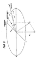
- the effect of the vertical component H y on the electron beams that affects the color purity is substantially the same at any directional angle ⁇ of the CRT.
- Directional angle ⁇ is defined as the angle between an electron beam axis Z of the CRT and the direction of the magnetic North. Therefore, automatic neutralization of the vertical component H y as a function of the directional angle ⁇ may not have a significant effect on color purity.
- directional angle ⁇ changes. It is well known that a change of angle ⁇ may tend to degrade or reduce the tolerance of the color purity in the CRT. It may be desirable to neutralize the horizontal component H h of the earth's magnetic field when directional angle ⁇ changes.
- a fluxgate magnetometer is used for generating first and second magnetic field sensing signals representative of corresponding magnetic field components of horizontal component H h of the earth's magnetic field.
- the sensing signals are applied to a pair of substantially planar coils disposed in a nonparallel, side-by-side vertical direction arrangement fitted on the periphery of the CRT.
- the sensing signals are used for generating corresponding currents in the coils that compensate or neutralize the effect of the horizontal component H h of the earth's magnetic field on the electron beam inside the CRT.
- the currents in the coils are automatically adjusted to compensate for the effect of the horizontal component H h of the earth's magnetic field.
- neutralization is obtained by directly interacting and sensing the horizontal component H h of the earth's magnetic field by means of the transducing magnetometer.
- the magnetometer generates the sense signals in a manner that is independently derived from the generation of the electron beam in CRT 10.
- the sense signals are independent of and unaffected by the beam landing position on the CRT screen.
- an optical output produced on the CRT screen by the electron beam is utilized for sensing the effect of the earth's magnetic field on the electron beam and for generating a neutralizing magnetic field in accordance with the direct effect of the earth's magnetic field on the electron beam landing position.
- Such prior art arrangement disadvantageously, requires a complicated optical interface with the CRT screen for monitoring the electron beam landing position on the CRT screen, and a complicated signal processing arrangement that may be costly.
- an apparatus for neutralizing a first magnetic field that undesirably affects electron beam landing in a video apparatus includes an arrangement responsive to the first magnetic field for generating a first sense signal that is indicative of a magnitude of the first magnetic field.
- a first current that is determined in accordance with the first magnetic field is generated.
- a first magnetic field neutralizing coil coupled to conduct the first current produces the neutralizing second magnetic field.
- the second magnetic field is of a magnitude that is in accordance with the magnitude of the first magnetic field. The second magnetic field automatically changes to maintain neutralization of the first magnetic field when a change in position of the video apparatus occurs.
- FIGURE 1 illustrates a fluxgate magnetometer 61 and a current driver arrangement, embodying an aspect of the invention, of, for example, a television receiver, for generating currents i11 and i12 that are applied to magnetic field neutralizing coils 11 and 12, respectively.
- coils 11 and 12 are fitted near CRT 10 of FIGURE 5 of the television receiver.
- Fluxgate magnetometer 61 of FIGURE 1 includes a drive winding 100 and a pair of sensing windings 100 U and 100 V , having axes U and V, respectively, that are, for example, perpendicular. The windings are constructed in the manner shown in FIGURE 6a. Similar symbols and numerals in FIGURES 1, 5 and 6a and 6b illustrate similar items or functions.
- Coils 11 and 12 of FIGURE 1 produce magnetic fields that are applied to the electron beam path of CRT 10 of FIGURE 5 for neutralizing the horizontal component of the earth's field, as described later on.
- Square wave current i in alternating from a positive value to a zero value at a frequency of, for example, 50 kH z , is applied to input terminals 100a and 100b of drive winding 100.
- toroidal core 150 of FIGURE 6a is unsaturated. Between transition times when current i in is flowing, the core is saturated.
- Toroidal core 150 and toroidal drive winding 100 confine the magnetic field produced by drive winding 100 to circular core 150 itself, so that, by itself, the circular magnetic field, that is produced as a result of current i in , induces a voltage of only a negligible amplitude into sensing windings 100 V and 100 U .
- the geometric symmetry of the toroidal core permits the use of more than one sensing winding on a single saturating core. The successful use of more than one sensing winding on a single core is contingent upon the selection of a core exhibiting uniform magnetic properties and cross-sectional area around its circumference.
- core 150 of FIGURE 6a When core 150 of FIGURE 6a becomes unsaturated, during transitions of current i in of FIGURE 1, the permeability of core 150 of FIGURE 6a becomes high. Therefore, the core material acts as a low impedance path to lines of magnetic flux in the surrounding environment, formed by horizontal component H h of the earth's magnetic field. When the core material is saturated, and its permeability is low, it no longer presents a low impedance path for external lines of flux, and they return to their original paths.
- the surrounding flux lines are drawn into it, cutting the winding turns of sensing windings 100 U and 100 V surrounding the core and inducing a voltage pulse S U in sensing winding 100 U , and a voltage pulse S V in sense winding 100 V .
- the flux lines caused by horizontal component H h of the earth's magnetic field are driven out of the core, generating a pulse of equal amplitude, but of opposite polarity.
- Pulses S V of FIGURE 1 are applied to an input terminal of an amplifier U1A through a resistor R6.
- a half-wave, phase-sensitive demodulator of pulses S V is implemented with an analog switch arrangement IC1, operating synchronously with current i in for shorting out the signal at the input terminal of amplifier U1A that is produced by sensing winding 100 V during the occurrence of alternate pulses of pulses S V .
- Such alternate pulses occur when core 150 of FIGURE 6a goes out of saturation.
- the other alternate pulses of pulses S V of FIGURE 1, occurring when core 150 of FIGURE 6a goes into saturation, are applied to the input terminal of amplifier U1A of FIGURE 1 to form a demodulated portion of signal S V .
- the demodulated portion of signal S V is voltage amplified in amplifier U1A low pass filtered by a capacitor C6 and applied via a variable voltage divider that includes a resistor R15 to an input terminal of a voltage amplifier U1B having a power stage 60 that includes transistors Q1 and Q2.
- an output voltage V out of output stage 60 that is indicative of that portion of horizontal component Hn of the earth's magnetic field of FIGURE 6b, which cuts across sensing winding 100 V , is applied via a resistor R V to neutralizing coil 11 of FIGURE 1.
- Variable resistor R15 is used for adjusting the level of current i11.
- current i12 that is adjustable by adjusting a resistor R24, is generated from pulses S U and flows in coil 12.
- neutralizing coils 11 and 12 produce corresponding magnetic fields that automatically neutralize the horizontal component H h of the earth's magnetic field at any directional angle ⁇ between the electron beam axis Z of CRT 10 of FIGURE 5 and the magnetic north.
- pulses S V and S U of FIGURE 1, that are used for generating currents i11 and i12, respectively, are unaffected by the magnetic fields that are produced by coils 11 and 12 of FIGURE 1.
- Such assumption is justified when the fluxgate magnetometer is located inside the television receiver cabinet, not shown in the FIGURES, but sufficiently far from coils 11 and 12.
- horizontal component H h has a direction that forms corresponding angles with axes U and V, respectively. Consequently, horizontal component H h may be vectorially separated into a first component H U having a direction that is coaxial with axis U and a second component H V having a direction that is coaxial with axis V and that is perpendicular to axis U.
- the amplitude of pulses S V is linearly proportional to the intensity of the surrounding magnetic field component H V which lies parallel to the axis V of sensing winding 100 V of FIGURE 6a.
- the amplitude of pulses S V of FIGURE 1 is unaffected by component H U of horizontal component H h of FIGURE 6b that is perpendicular to axis V.
- the polarity of pulses S V of FIGURE 1 depends upon the vectorial direction of component H V with respect to sensing winding 100 V of FIGURE 6a that, in turn, is determined by directional angle ⁇ of FIGURE 5.
- the polarity and amplitude relationship between pulses S U of sensing winding 100 U and field component H U is analogous to that between pulses S V and field component H V .
- pulses S V and S U are representative of components H V and H U , respectively.
- current i11 of FIGURE 1 is linearly proportional to pulses S V , it is also linearly proportional to component H V of FIGURE 6b and is unaffected by component H U of the horizontal component H h of the earth's magentic field.
- current i12 in coil 12 of FIGURE 1 is linearly proportional to component H U of FIGURE 6b but is unaffected by component H U of the horizontal component H h of the earth's magnetic field.
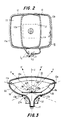
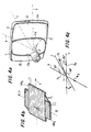
- FIGURES 2, 3 and 4a illustrates neutralizing coils 11 and 12 of FIGURE 1, mentioned before, that are fitted on CRT 10.
- Coils 11 and 12 of FIGURE 1 are used for producing a resultant neutralizing magnetic field that neutralizes the effect of horizontal component H h of the earth's magnetic field on the electron beam in CRT 10.
- Similar symbols and numerals in FIGURES 1-6 indicate similar items or functions.
- Neutralizing coils 11 and 12 of FIGURE 3 are fitted along the outer periphery of CRT 10 to spatially surround a magnetic shield 16 of FIGURES 3 received within a conical section 22 of CRT 10.
- Inner vertical portions 11b and 12b of neutralizing coils 11 and 12, respectively, partly surround a neck section 17 of CRT 10 and intersect each other at vertically disposed two opposite points across neck section 17.
- Inner portions 11b and 12b are disposed between a rear end portion 16b of magnetic shield 16 and a forward end portion 27a of a deflection yoke arrangement 27.
- Outer portions 11a and 12a of coils 11 and 12, respectively, are positioned near a shadow mask 16a, which is also part of magnetic shield 16b in parallel relationship with inner portions 11b and 12b, respectively.
- the number of turns in each coil may be such so as to provide the required number of ampere-turns, such as, three, for example. It should be understood that deflection yoke arrangement 27 is not shown in FIGURE 4a so as to provide a better view of coils 11 and 12.
- portions 11a and 11b of coil 11 define a vertical plane having an axis V′ of coil 11 that is perpendicular to such horizontal plane.
- the spatial orientation between coil 11 and winding 100 V of fluxgate magnetometer 61, shown in FIGURE 4b, is arranged such that the axis V of winding 100 V is close to being in parallel with the axis V′ of coil 11 as shown in FIGURE 3.
- coil 12 defines a corresponding vertical plane having an axis U′ of FIGURE 2 that is close to being in parallel with axis U of winding 100 U .
- Magnetometer 61 of FIGURE 4b is secured in a cabinet of the television receiver, not shown in the Figures, behind the back portion of CRT 10 of, for example, FIGURE 4a.
- the orientation of axes U and V of magnetometer 61 relative to CRT 10 is shown in FIGURE 3.
- Axes U and V are disposed approximately symmetrically relative to axis Z of CRT 10.
- the magnitude and polarity of current i11 of FIGURE 1 may be manually adjusted by varying resistor R15 so as to produce magnetic field H11 of FIGURE 4c at the opposite direction and at the same magnitude of component H V .
- magnetic field H11 neutralizes component H V or reduces the effect of component H V of horizontal component H h of the earth's magnetic field on the electron beam of CRT 10.
- Such adjustment of current i11 of FIGURE 1 is made in a given geographical location such as, for example, at the factory and at a given direction angle ⁇ of CRT 10 of FIGURE 5.
- current i12 of FIGURE 1 is manually adjusted so as to produce magnetic field H12 that neutralizes component H U .
- horizontal component H h of the earth's magnetic field is neutralized.
- Magnetic field H11 is linearly proportional to component H V , as described before.
- Magnetic field H11 is linearly proportional to component H V , is in a direction that opposes that of component H V and is unaffected by component H U .
- the above mentioned relationship between magnetic field H11 and component H V is maintained at any directional angle ⁇ of CRT 10 of FIGURE 5.
- a similar, corresponding relationship between magnetic field H12 of FIGURE 4c and component H U is also maintained at any angle ⁇ .
Landscapes
- Engineering & Computer Science (AREA)
- Multimedia (AREA)
- Signal Processing (AREA)
- Measuring Magnetic Variables (AREA)
- Video Image Reproduction Devices For Color Tv Systems (AREA)
- Testing, Inspecting, Measuring Of Stereoscopic Televisions And Televisions (AREA)
Applications Claiming Priority (2)
| Application Number | Priority Date | Filing Date | Title |
|---|---|---|---|
| US07/240,321 US4950955A (en) | 1988-09-06 | 1988-09-06 | Magnetic field compensator for a CRT |
| US240321 | 1988-09-06 |
Publications (3)
| Publication Number | Publication Date |
|---|---|
| EP0358133A2 true EP0358133A2 (de) | 1990-03-14 |
| EP0358133A3 EP0358133A3 (de) | 1992-10-28 |
| EP0358133B1 EP0358133B1 (de) | 1998-01-14 |
Family
ID=22906077
Family Applications (1)
| Application Number | Title | Priority Date | Filing Date |
|---|---|---|---|
| EP89116221A Expired - Lifetime EP0358133B1 (de) | 1988-09-06 | 1989-09-02 | Magnetfeldkompensator für eine Kathodenstrahlröhre |
Country Status (7)
| Country | Link |
|---|---|
| US (1) | US4950955A (de) |
| EP (1) | EP0358133B1 (de) |
| JP (1) | JPH02108388A (de) |
| KR (1) | KR0144731B1 (de) |
| DE (1) | DE68928541T2 (de) |
| FI (1) | FI93414C (de) |
| SG (1) | SG95571A1 (de) |
Cited By (2)
| Publication number | Priority date | Publication date | Assignee | Title |
|---|---|---|---|---|
| EP0460757A3 (en) * | 1990-06-08 | 1992-10-28 | Koninkl Philips Electronics Nv | Circuit for the compensation of the horizontal component of the earth's magnetic field for a colour picture tube of a high-resolution monitor |
| EP1363310A3 (de) * | 2002-05-14 | 2006-05-03 | Matsushita Electric Industrial Co., Ltd. | Kathodenstrahlröhre, Vorrichtung mit Kathodenstrahlröhre, Bildanzeigegerät und Spuleneinheit |
Families Citing this family (12)
| Publication number | Priority date | Publication date | Assignee | Title |
|---|---|---|---|---|
| JP2612044B2 (ja) * | 1988-07-21 | 1997-05-21 | 株式会社日立製作所 | 電子ファイル装置 |
| JP2981252B2 (ja) * | 1990-03-28 | 1999-11-22 | 株式会社東芝 | 消磁回路 |
| US5157308A (en) * | 1991-08-06 | 1992-10-20 | Sun Microsystems, Inc. | Methods and apparatus for reducing electromagnetic interference emission from a cathode ray tube video display system |
| US5168195A (en) * | 1991-08-09 | 1992-12-01 | Thomson Consumer Electronics, Inc. | Magnetic field compensation apparatus |
| US5382875A (en) * | 1992-08-10 | 1995-01-17 | Zenith Electronics Corporation | Stray magnetic field suppresser for CRT image displays |
| US5594615A (en) * | 1993-05-10 | 1997-01-14 | Mti, Inc. | Method and apparatus for reducing the intensity of magenetic field emissions from display device |
| US5561333A (en) * | 1993-05-10 | 1996-10-01 | Mti, Inc. | Method and apparatus for reducing the intensity of magnetic field emissions from video display units |
| JPH07162882A (ja) * | 1993-12-10 | 1995-06-23 | Sony Corp | 陰極線管装置 |
| KR0182920B1 (ko) * | 1996-05-02 | 1999-10-01 | 김광호 | 이미지 로테이션 자동 보상 회로 및 보상 방법 |
| KR100208905B1 (ko) * | 1996-09-13 | 1999-07-15 | 구자홍 | 퓨리티 조정장치 |
| US6232775B1 (en) * | 1997-12-26 | 2001-05-15 | Alps Electric Co., Ltd | Magneto-impedance element, and azimuth sensor, autocanceler and magnetic head using the same |
| US6741296B1 (en) | 2000-01-04 | 2004-05-25 | International Business Machines Corporation | Multi-hemisphere color CRT |
Family Cites Families (10)
| Publication number | Priority date | Publication date | Assignee | Title |
|---|---|---|---|---|
| US463911A (en) * | 1891-11-24 | Stone-breaker | ||
| US2925524A (en) * | 1956-03-16 | 1960-02-16 | Gen Electric | Methods and structures correcting for beam deflections in a television picture tube |
| US2921226A (en) * | 1956-05-24 | 1960-01-12 | Philco Corp | Apparatus for color purity correction in color television receivers |
| US3757154A (en) * | 1971-03-03 | 1973-09-04 | Sony Corp | Magnetic field on color television receivers apparatus for automatically eliminating the influence of the earth s |
| DE3017331A1 (de) * | 1980-05-06 | 1981-11-12 | Siemens AG, 1000 Berlin und 8000 München | Anordnung zur kompensation von auf farbfernsehroehren einwirkenden magnetischen fremdfeldern |
| US4380716A (en) * | 1981-10-09 | 1983-04-19 | Hazeltine Corporation | External magnetic field compensator for a CRT |
| US4535270A (en) * | 1983-11-17 | 1985-08-13 | Rca Corporation | Resonant degaussing without residual magnetism |
| US4636911A (en) * | 1984-11-30 | 1987-01-13 | Rca Corporation | Resonant degaussing for a video display system |
| US4742270A (en) * | 1985-09-30 | 1988-05-03 | Rca Corporation | Degaussing circuit with residual current cutoff |
| US4760489A (en) * | 1987-06-12 | 1988-07-26 | Rca Licensing Corporation | Video display degaussing apparatus |
-
1988
- 1988-09-06 US US07/240,321 patent/US4950955A/en not_active Expired - Lifetime
-
1989
- 1989-08-30 FI FI894060A patent/FI93414C/fi not_active IP Right Cessation
- 1989-09-01 KR KR1019890012613A patent/KR0144731B1/ko not_active Expired - Fee Related
- 1989-09-02 DE DE68928541T patent/DE68928541T2/de not_active Expired - Fee Related
- 1989-09-02 EP EP89116221A patent/EP0358133B1/de not_active Expired - Lifetime
- 1989-09-02 SG SG9601916A patent/SG95571A1/en unknown
- 1989-09-05 JP JP1231325A patent/JPH02108388A/ja active Pending
Cited By (2)
| Publication number | Priority date | Publication date | Assignee | Title |
|---|---|---|---|---|
| EP0460757A3 (en) * | 1990-06-08 | 1992-10-28 | Koninkl Philips Electronics Nv | Circuit for the compensation of the horizontal component of the earth's magnetic field for a colour picture tube of a high-resolution monitor |
| EP1363310A3 (de) * | 2002-05-14 | 2006-05-03 | Matsushita Electric Industrial Co., Ltd. | Kathodenstrahlröhre, Vorrichtung mit Kathodenstrahlröhre, Bildanzeigegerät und Spuleneinheit |
Also Published As
| Publication number | Publication date |
|---|---|
| FI894060A0 (fi) | 1989-08-30 |
| DE68928541T2 (de) | 1998-06-04 |
| DE68928541D1 (de) | 1998-02-19 |
| US4950955A (en) | 1990-08-21 |
| KR900005806A (ko) | 1990-04-14 |
| EP0358133A3 (de) | 1992-10-28 |
| KR0144731B1 (ko) | 1998-07-15 |
| FI93414C (fi) | 1995-03-27 |
| FI894060A7 (fi) | 1990-03-07 |
| EP0358133B1 (de) | 1998-01-14 |
| FI93414B (fi) | 1994-12-15 |
| JPH02108388A (ja) | 1990-04-20 |
| SG95571A1 (en) | 2003-04-23 |
Similar Documents
| Publication | Publication Date | Title |
|---|---|---|
| EP0358133B1 (de) | Magnetfeldkompensator für eine Kathodenstrahlröhre | |
| US4963789A (en) | Method and apparatus for dynamic magnetic field neutralization | |
| EP0456942B1 (de) | Ablenkjoch mit überlappenden Ablenkspulen | |
| US5017832A (en) | Magnetic cancelling apparatus for color cathode-ray tube | |
| US4864192A (en) | CRT magnetic field compensation | |
| JPH01217839A (ja) | 補償コイルを有する磁化可能なコアをそなえた画像表示装置 | |
| EP0797837A1 (de) | Farbanzeigevorrichtung mit anordnung zur korrektur von landungsfehlern | |
| PL118815B1 (en) | Method for correction of colour purity | |
| EP0487796B1 (de) | Kathodenstrahlröhrenanzeigeapparat | |
| US4316119A (en) | Tilted unitary degaussing coil arrangement | |
| EP0657913B1 (de) | Elektronenstrahlröhre mit erdmagnetismussensoren | |
| US5473221A (en) | Bucking field system and method for mitigating the effects of an external magnetic field on a cathode ray tube display | |
| US5705899A (en) | CRT display having compensation for image rotation and convergence errors | |
| US5488270A (en) | Color CRT display apparatus | |
| KR970014404A (ko) | 컬러 음극선관 디스플레이장치 및 그 색순도 조정방법 | |
| GB1574266A (en) | Pickup tube structure with a magnetic shield | |
| JPH03261037A (ja) | カラー受像管の製造方法 | |
| US4429258A (en) | Electron beam alignment in tube/coil assemblies | |
| US3435276A (en) | Convergence apparatus for nullifying unwanted induced deflection currents | |
| US3273008A (en) | Dynamic convergence systems for colour kinescopes | |
| EP1206792A1 (de) | Anzeigevorrichtung mit einer ablenkeinheit | |
| JPH03232387A (ja) | カラー陰極線管ディスプレイ装置 | |
| JPH0566726A (ja) | ランデイング補正装置 | |
| JP3320926B2 (ja) | カラーcrt及びその調整方法 | |
| EP0730290A1 (de) | Ablenkeinheit mit Verzerrungskorrekturspule in einer Kathodenstrahlröhre |
Legal Events
| Date | Code | Title | Description |
|---|---|---|---|
| PUAI | Public reference made under article 153(3) epc to a published international application that has entered the european phase |
Free format text: ORIGINAL CODE: 0009012 |
|
| AK | Designated contracting states |
Kind code of ref document: A2 Designated state(s): DE FR GB IT |
|
| PUAL | Search report despatched |
Free format text: ORIGINAL CODE: 0009013 |
|
| AK | Designated contracting states |
Kind code of ref document: A3 Designated state(s): DE FR GB IT |
|
| 17P | Request for examination filed |
Effective date: 19930330 |
|
| 17Q | First examination report despatched |
Effective date: 19930630 |
|
| GRAG | Despatch of communication of intention to grant |
Free format text: ORIGINAL CODE: EPIDOS AGRA |
|
| GRAG | Despatch of communication of intention to grant |
Free format text: ORIGINAL CODE: EPIDOS AGRA |
|
| GRAH | Despatch of communication of intention to grant a patent |
Free format text: ORIGINAL CODE: EPIDOS IGRA |
|
| GRAH | Despatch of communication of intention to grant a patent |
Free format text: ORIGINAL CODE: EPIDOS IGRA |
|
| GRAA | (expected) grant |
Free format text: ORIGINAL CODE: 0009210 |
|
| AK | Designated contracting states |
Kind code of ref document: B1 Designated state(s): DE FR GB IT |
|
| REF | Corresponds to: |
Ref document number: 68928541 Country of ref document: DE Date of ref document: 19980219 |
|
| ITF | It: translation for a ep patent filed | ||
| ET | Fr: translation filed | ||
| PLBE | No opposition filed within time limit |
Free format text: ORIGINAL CODE: 0009261 |
|
| STAA | Information on the status of an ep patent application or granted ep patent |
Free format text: STATUS: NO OPPOSITION FILED WITHIN TIME LIMIT |
|
| 26N | No opposition filed | ||
| REG | Reference to a national code |
Ref country code: GB Ref legal event code: IF02 |
|
| REG | Reference to a national code |
Ref country code: FR Ref legal event code: D6 |
|
| REG | Reference to a national code |
Ref country code: GB Ref legal event code: 746 Effective date: 20030103 |
|
| PGFP | Annual fee paid to national office [announced via postgrant information from national office to epo] |
Ref country code: GB Payment date: 20060804 Year of fee payment: 18 |
|
| PGFP | Annual fee paid to national office [announced via postgrant information from national office to epo] |
Ref country code: FR Payment date: 20060914 Year of fee payment: 18 |
|
| PGFP | Annual fee paid to national office [announced via postgrant information from national office to epo] |
Ref country code: DE Payment date: 20060918 Year of fee payment: 18 |
|
| PGFP | Annual fee paid to national office [announced via postgrant information from national office to epo] |
Ref country code: IT Payment date: 20060930 Year of fee payment: 18 |
|
| GBPC | Gb: european patent ceased through non-payment of renewal fee |
Effective date: 20070902 |
|
| PG25 | Lapsed in a contracting state [announced via postgrant information from national office to epo] |
Ref country code: DE Free format text: LAPSE BECAUSE OF NON-PAYMENT OF DUE FEES Effective date: 20080401 |
|
| REG | Reference to a national code |
Ref country code: FR Ref legal event code: ST Effective date: 20080531 |
|
| PG25 | Lapsed in a contracting state [announced via postgrant information from national office to epo] |
Ref country code: FR Free format text: LAPSE BECAUSE OF NON-PAYMENT OF DUE FEES Effective date: 20071001 |
|
| PG25 | Lapsed in a contracting state [announced via postgrant information from national office to epo] |
Ref country code: GB Free format text: LAPSE BECAUSE OF NON-PAYMENT OF DUE FEES Effective date: 20070902 |
|
| PG25 | Lapsed in a contracting state [announced via postgrant information from national office to epo] |
Ref country code: IT Free format text: LAPSE BECAUSE OF NON-PAYMENT OF DUE FEES Effective date: 20070902 |