EP0357737B1 - Improvements in or relating to lift shafts - Google Patents
Improvements in or relating to lift shafts Download PDFInfo
- Publication number
- EP0357737B1 EP0357737B1 EP89903122A EP89903122A EP0357737B1 EP 0357737 B1 EP0357737 B1 EP 0357737B1 EP 89903122 A EP89903122 A EP 89903122A EP 89903122 A EP89903122 A EP 89903122A EP 0357737 B1 EP0357737 B1 EP 0357737B1
- Authority
- EP
- European Patent Office
- Prior art keywords
- module
- shaft
- lift
- modules
- car
- Prior art date
- Legal status (The legal status is an assumption and is not a legal conclusion. Google has not performed a legal analysis and makes no representation as to the accuracy of the status listed.)
- Expired
Links
Images

Classifications
-
- E—FIXED CONSTRUCTIONS
- E04—BUILDING
- E04F—FINISHING WORK ON BUILDINGS, e.g. STAIRS, FLOORS
- E04F17/00—Vertical ducts; Channels, e.g. for drainage
- E04F17/005—Lift shafts
-
- B—PERFORMING OPERATIONS; TRANSPORTING
- B66—HOISTING; LIFTING; HAULING
- B66B—ELEVATORS; ESCALATORS OR MOVING WALKWAYS
- B66B19/00—Mining-hoist operation
-
- E—FIXED CONSTRUCTIONS
- E04—BUILDING
- E04B—GENERAL BUILDING CONSTRUCTIONS; WALLS, e.g. PARTITIONS; ROOFS; FLOORS; CEILINGS; INSULATION OR OTHER PROTECTION OF BUILDINGS
- E04B1/00—Constructions in general; Structures which are not restricted either to walls, e.g. partitions, or floors or ceilings or roofs
- E04B1/348—Structures composed of units comprising at least considerable parts of two sides of a room, e.g. box-like or cell-like units closed or in skeleton form
- E04B1/34869—Elements for special technical purposes, e.g. with a sanitary equipment
-
- Y—GENERAL TAGGING OF NEW TECHNOLOGICAL DEVELOPMENTS; GENERAL TAGGING OF CROSS-SECTIONAL TECHNOLOGIES SPANNING OVER SEVERAL SECTIONS OF THE IPC; TECHNICAL SUBJECTS COVERED BY FORMER USPC CROSS-REFERENCE ART COLLECTIONS [XRACs] AND DIGESTS
- Y10—TECHNICAL SUBJECTS COVERED BY FORMER USPC
- Y10S—TECHNICAL SUBJECTS COVERED BY FORMER USPC CROSS-REFERENCE ART COLLECTIONS [XRACs] AND DIGESTS
- Y10S52/00—Static structures, e.g. buildings
- Y10S52/12—Temporary protective expedient
Definitions
- the invention provides a lift shaft comprising a stack of separate self-supporting prefabricated shaft modules, used as containers to carry a fully assembled lift car and a counterweight between the factory and the building site, each module having a structural strength sufficient to support the module or modules above whereby the shaft can be supported from a lower module, an uppermost module containing winding apparatus for a lift car and a counterweight to raise and lower the car and a counterweight in the shaft and each module having door means operable in conjunction with the lift car to provide access to and from the car when the car is disposed in the respective module.
- lift shaft system defined above provides a much faster way of installing and commissioning lifts involving prefabricating lift shaft modules including lift motor rooms for erection on site.
- the lift shafts are made, preferably, of sheet steel sections which are joined together to form tubes with open tops and bottoms.
- These tubes are typically sized to meet individual building floor to floor height dimensions and the number of lifts required in each shaft. The only restrictions imposed on the sizing of the shafts is determined by transportation or crane capacity limitations.
- a lift shaft construction of this kind is known from the DD-PS 90202.
- the shaft modules are made of sheet steel or plastics.
- the lowermost module is bolted on a base plate.
- the upper and lower peripheries of the modules have flange fittings with guide brackets. Once stacked the modules are bolted or bonded.
- the uppermost module contains the equipment to raise and lower the lift car in the shaft.
- the invention has the purpose of the creation of lift shaft modules enabling an economical and simple erection of lift shafts. This purpose is net by the lift shaft according to claim 1.
- the advantage attained by the invention is to be seen substantially in that the lift shaft modules with all the equipment can be fitted under factory conditions away from the building site.
- the lift shaft modules are designed so that they can be used as containers for fully assembled lift cars and/or counterweights between the factory and the building site so that a lift shaft module can be craned into position with complete car and/or counterweight.
- One of the modules is prefabricated with the lift car and/or counterweight installed and temporarily supported in the module for transport to a direction on site, the arrangement being such that once the module has been erected, the car and the counterweight are coupled to the winding means in the uppermost module and the temporary support for the car and the counterweight in the module is then released to enable the car and the counterweight to be raised and lowered in the shaft.
- Each storey height lift shaft module leaves the factory as a sealed weatherproof containerlike unit.
- the top and bottom openings of each lift shaft module are sealed with translucent glass fibre reinforced plastic (G.R.P.) covers.
- the bottom cover is removed on site shortly before each module is craned into position. The top cover remains until shortly before the next module is due to be placed in position.
- the ribs of the channel sections of the lift shafts are spaced and sized to facilitate the attachment on site of plasterboard sheets which provide the requisite fire resistance for the lift shafts.
- the design of the channel sections is such that they can be used as permanent shuttering for in-situ concrete lift shafts if required (as described in U.K. Patent No. 2015615).
- the design of the joints is such that they provide seals against penetration of fire and smoke using a fire stop compound applied from both above and below the joint.
- the underside of the junction between the pressed metal formwork and the upper face of the lower steel angle is sealed using a gunned firestop mastic compound and then a liquid fire stop compound is applied to the top side of the pressed metal formwork.
- a resilient foam plastic strip (which also seals the joint between the lift shaft and the G.R.P. covers) prevents rainwater or fire stop compound in its liquid state from entering the lift shaft during the erection phase.
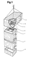
- the lift shaft comprises prefabricated fully assembled shaft modules 1 including one or more plain modules, a module in which a fully assembled lift car 2 and/or a not shown counterweight are temporarily supported for transit to the site and erection on site, a fully assembled upper lift motor room module 3 including winding apparatus 4 and electronic equipment 5 for the lift and a pit module 6 suspended from the module 1 above to lie in a preformed pit 7 in the lowermost part of the building.
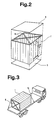
- a temporary cross-bracing fixed to the top and the bottom for transit of the modules 1; 3; 6 is designated by 8 and a weatherproof temporary transluscent G.R.P. cover bolted to the top and the bottom for transport of the modules 1; 3; 6 is designated by 9.
- In transport the door opening of a module is located lowermost on a transport vehicle 10.
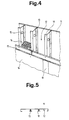
- Figs. 5 and 8 depict a plan of alternative wall panel profiles.
- the modules 1; 3; 6 have walls formed from vertically extending channel section members of galvanized steel sheets 11. They are rivetted or press jointed together side by side with the channels facing outwardly of the shaft whereby the basis of channels 12 form a continuous internal surface around the shaft.
- the joint 13 of the steel sheets is sealed by a mastic.
- mineral wool 14 bonded to steel is provided to reduce sound transmission and drumming.
- Prepunched openings for services are designated by 15.
- Two thicknesses of plasterboard 16; 17 with lapped joints are screwed to the steel ribs 18 of the module.
- the joints of the outer plasterboards 16 are closed by a taperedged plasterboard 19.
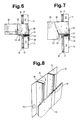
- a joint between adjacent upper and lower modules are shown in Figs. 6 and 7.
- the upper and lower peripheries of the modules 1; 3; 6 have encircling flanges 20 and the modules are stacked with spacer means in the form of shim plates 21 between the adjacent flanges 20.
- Compressible weather sealing strips 22 are located between the shim plates 21.
- Bolts and locating pins permit fast and acurate plumbing of the modules when installing them on site.
- a preformed metal formwork 23 is provided and filled with a fire stop compound 24 and dryish concrete 25 to ensure a fire and smoke resistant joint between lift modules.
- a concrete floor 26 is formed at the level of the fire and smoke resistant joint.
- Figs. 9 and 10 depict lift shafts wall construction options.
- the module walls are used as permanent shuttering and reinforcement for in-situ concrete lift shafts whereby the shaft wall consists of steel sheets 11 and a fill of in-situ concrete 27.
- Fig. 11 shows a vertical section trough the lowermost or pit module 6 extending into the pit 7 in the basement 28 of the building and being suspended from the module 1 of the first floor 29.
- the first floor module 1 is adapted to be supported in the structure of the building to support the modules 1; 3 of the shaft above. If necessary, the lift pit can be incorporated into the pit module 6. If so, an integral floor 30 is provided in the lowermost module 6. The structural loads of the pit module 6 are carried to the module above and transferred to the adjacent floor structure.
Abstract
Description
- The invention provides a lift shaft comprising a stack of separate self-supporting prefabricated shaft modules, used as containers to carry a fully assembled lift car and a counterweight between the factory and the building site, each module having a structural strength sufficient to support the module or modules above whereby the shaft can be supported from a lower module, an uppermost module containing winding apparatus for a lift car and a counterweight to raise and lower the car and a counterweight in the shaft and each module having door means operable in conjunction with the lift car to provide access to and from the car when the car is disposed in the respective module.
- Thus the lift shaft system defined above provides a much faster way of installing and commissioning lifts involving prefabricating lift shaft modules including lift motor rooms for erection on site.
- The lift shafts are made, preferably, of sheet steel sections which are joined together to form tubes with open tops and bottoms.
- These tubes are typically sized to meet individual building floor to floor height dimensions and the number of lifts required in each shaft. The only restrictions imposed on the sizing of the shafts is determined by transportation or crane capacity limitations.
- A lift shaft construction of this kind is known from the DD-PS 90202. The shaft modules are made of sheet steel or plastics. The lowermost module is bolted on a base plate. The upper and lower peripheries of the modules have flange fittings with guide brackets. Once stacked the modules are bolted or bonded. The uppermost module contains the equipment to raise and lower the lift car in the shaft.
- The main disadavantage of the known lift shaft construction lies in the extensive requirement for skilled on site labour for lift installation work. Another disadvantage is that for the inherent equipment of the modules there is neither a weather proof nor a dirt proof protection during transport and on site installation work.
- The invention has the purpose of the creation of lift shaft modules enabling an economical and simple erection of lift shafts. This purpose is net by the lift shaft according to
claim 1. - The advantage attained by the invention is to be seen substantially in that the lift shaft modules with all the equipment can be fitted under factory conditions away from the building site.
- The lift shaft modules are designed so that they can be used as containers for fully assembled lift cars and/or counterweights between the factory and the building site so that a lift shaft module can be craned into position with complete car and/or counterweight. One of the modules is prefabricated with the lift car and/or counterweight installed and temporarily supported in the module for transport to a direction on site, the arrangement being such that once the module has been erected, the car and the counterweight are coupled to the winding means in the uppermost module and the temporary support for the car and the counterweight in the module is then released to enable the car and the counterweight to be raised and lowered in the shaft.
- Each storey height lift shaft module leaves the factory as a sealed weatherproof containerlike unit. The top and bottom openings of each lift shaft module are sealed with translucent glass fibre reinforced plastic (G.R.P.) covers. The bottom cover is removed on site shortly before each module is craned into position. The top cover remains until shortly before the next module is due to be placed in position.
- The ribs of the channel sections of the lift shafts are spaced and sized to facilitate the attachment on site of plasterboard sheets which provide the requisite fire resistance for the lift shafts. The design of the channel sections is such that they can be used as permanent shuttering for in-situ concrete lift shafts if required (as described in U.K. Patent No. 2015615).
- The design of the joints between each lift shaft section is such that they can be plumbed and levelled quickly and accurately. Tolerances achieved are far lower than those normally possible for traditionally constructed lift shafts.
- The design of the joints is such that they provide seals against penetration of fire and smoke using a fire stop compound applied from both above and below the joint. The underside of the junction between the pressed metal formwork and the upper face of the lower steel angle is sealed using a gunned firestop mastic compound and then a liquid fire stop compound is applied to the top side of the pressed metal formwork. A resilient foam plastic strip (which also seals the joint between the lift shaft and the G.R.P. covers) prevents rainwater or fire stop compound in its liquid state from entering the lift shaft during the erection phase.
- The following is a description of same specific embodiments of the invention reference being made to the accompanying drawing in which:
- Fig. 1
- is a perspective view of a lift shaft according to the invention comprising prefabricated shaft modules;
- Fig. 2
- is a perspective view of one of the modules showing temporary cross-bracing and covers for transport;
- Fig. 3
- illustrates the module of Fig. 2 in transport;
- Fig. 4
- is a perspective view of part of a wall construction for each lift module;
- Fig. 5
- illustrates an alternative section panel for the walls;
- Fig. 6
- illustrates a joint between adjacent upper and lower modules;
- Fig. 7
- illustrates an alternative floor construction adjacent the joint between the modules;
- Fig. 8 to 10
- illustrate further constructional features and
- Fig. 11
- illustrates the arrangements of the lowermost module.
- In the Figs. 1 to 11 the lift shaft comprises prefabricated fully assembled
shaft modules 1 including one or more plain modules, a module in which a fully assembledlift car 2 and/or a not shown counterweight are temporarily supported for transit to the site and erection on site, a fully assembled upper liftmotor room module 3 including winding apparatus 4 andelectronic equipment 5 for the lift and apit module 6 suspended from themodule 1 above to lie in apreformed pit 7 in the lowermost part of the building. A temporary cross-bracing fixed to the top and the bottom for transit of themodules 1; 3; 6 is designated by 8 and a weatherproof temporary transluscent G.R.P. cover bolted to the top and the bottom for transport of themodules 1; 3; 6 is designated by 9. In transport the door opening of a module is located lowermost on atransport vehicle 10. - An external facing of the lift shaft is shown in Fig. 4. Figs. 5 and 8 depict a plan of alternative wall panel profiles. The
modules 1; 3; 6 have walls formed from vertically extending channel section members of galvanizedsteel sheets 11. They are rivetted or press jointed together side by side with the channels facing outwardly of the shaft whereby the basis ofchannels 12 form a continuous internal surface around the shaft. The joint 13 of the steel sheets is sealed by a mastic. In thechannels 12mineral wool 14 bonded to steel is provided to reduce sound transmission and drumming. Prepunched openings for services are designated by 15. Two thicknesses ofplasterboard 16; 17 with lapped joints are screwed to thesteel ribs 18 of the module. The joints of theouter plasterboards 16 are closed by ataperedged plasterboard 19. - Details of a joint between adjacent upper and lower modules are shown in Figs. 6 and 7. The upper and lower peripheries of the
modules 1; 3; 6 haveencircling flanges 20 and the modules are stacked with spacer means in the form ofshim plates 21 between theadjacent flanges 20. Compressible weather sealing strips 22 are located between theshim plates 21. Bolts and locating pins permit fast and acurate plumbing of the modules when installing them on site. On the inner side of the joint a preformedmetal formwork 23 is provided and filled with afire stop compound 24 and dryish concrete 25 to ensure a fire and smoke resistant joint between lift modules. At the level of the fire and smoke resistant joint aconcrete floor 26 is formed. - Figs. 9 and 10 depict lift shafts wall construction options. The module walls are used as permanent shuttering and reinforcement for in-situ concrete lift shafts whereby the shaft wall consists of
steel sheets 11 and a fill of in-situ concrete 27. - Fig. 11 shows a vertical section trough the lowermost or
pit module 6 extending into thepit 7 in thebasement 28 of the building and being suspended from themodule 1 of thefirst floor 29. Thefirst floor module 1 is adapted to be supported in the structure of the building to support themodules 1; 3 of the shaft above. If necessary, the lift pit can be incorporated into thepit module 6. If so, anintegral floor 30 is provided in thelowermost module 6. The structural loads of thepit module 6 are carried to the module above and transferred to the adjacent floor structure.
Claims (4)
Applications Claiming Priority (2)
| Application Number | Priority Date | Filing Date | Title |
|---|---|---|---|
| GB888806063A GB8806063D0 (en) | 1988-03-15 | 1988-03-15 | Improvements in/relating to lift shafts |
| GB8806063 | 1988-03-15 |
Publications (2)
| Publication Number | Publication Date |
|---|---|
| EP0357737A1 EP0357737A1 (en) | 1990-03-14 |
| EP0357737B1 true EP0357737B1 (en) | 1991-08-14 |
Family
ID=10633419
Family Applications (1)
| Application Number | Title | Priority Date | Filing Date |
|---|---|---|---|
| EP89903122A Expired EP0357737B1 (en) | 1988-03-15 | 1989-03-09 | Improvements in or relating to lift shafts |
Country Status (9)
| Country | Link |
|---|---|
| US (1) | US5012621A (en) |
| EP (1) | EP0357737B1 (en) |
| JP (1) | JPH02503421A (en) |
| CA (1) | CA1330652C (en) |
| FI (1) | FI92509C (en) |
| GB (2) | GB8806063D0 (en) |
| IL (1) | IL89553A (en) |
| SG (1) | SG79892G (en) |
| WO (1) | WO1989008753A1 (en) |
Cited By (1)
| Publication number | Priority date | Publication date | Assignee | Title |
|---|---|---|---|---|
| CN111877691A (en) * | 2020-08-12 | 2020-11-03 | 湖南建工五建建筑工业化有限公司 | Prefabricated stacked elevator shaft and installation method thereof |
Families Citing this family (32)
| Publication number | Priority date | Publication date | Assignee | Title |
|---|---|---|---|---|
| GB8829603D0 (en) * | 1988-12-19 | 1989-02-08 | New Domain Limited | Improvements in or relating to lift shafts |
| AU625660B2 (en) * | 1989-06-16 | 1992-07-16 | Boral Johns Perry Industries Pty Ltd | Lift shaft construction |
| US5127201A (en) * | 1990-03-26 | 1992-07-07 | Joseph Skvaril | Prefabricated compact sevice core |
| DE4223017A1 (en) * | 1992-07-13 | 1994-01-20 | Oliver Dipl Ing Franz | Elevator shaft for multi-storey prefabricated houses |
| ES2068146B1 (en) * | 1993-05-25 | 1998-02-16 | Desarrollos Tecnicos Patentado | MODULAR ENCLOSURE, PREFABRICATED OF REINFORCED CONCRETE, FOR ELEVATORS. |
| GB9313056D0 (en) * | 1993-06-24 | 1993-08-11 | Collmain Customer Serv Ltd | People-accomodating cavity shaft |
| US5813174A (en) * | 1996-03-28 | 1998-09-29 | Waller; James E. | Closet vault |
| US5921034A (en) * | 1997-05-02 | 1999-07-13 | Tobin; Timothy J. | Transportable workshop |
| JP2001058783A (en) * | 1999-07-12 | 2001-03-06 | Inventio Ag | Elevator facility with elevator shaft door |
| US6425463B1 (en) * | 2000-03-15 | 2002-07-30 | Frederick Kenneth Broyan | Non-personnel lifting device |
| GB2363110B (en) * | 2000-03-18 | 2004-03-10 | Wayne Toghill | Lift shafts |
| DE10121565A1 (en) * | 2001-04-28 | 2002-11-21 | Reinhardt Schmidt | Lift shaft for buildings, comprises tube of walled segments plus hollow foam-packed segments with storey lift door |
| EP1321419A1 (en) * | 2001-12-21 | 2003-06-25 | Inventio Ag | Drive module for a modular lift shaft |
| RU2218298C1 (en) * | 2002-05-31 | 2003-12-10 | Тарасов Александр Владимирович | Lifting complex |
| US20080099283A1 (en) * | 2006-10-25 | 2008-05-01 | Robert Jacobus Reigwein | Lift Apparatus and Method for Forming Same |
| JP2010202398A (en) * | 2009-03-05 | 2010-09-16 | Toshiba Elevator Co Ltd | Mold unit for structuring uppermost end part of hoistway |
| NL2002869C2 (en) * | 2009-05-11 | 2010-11-18 | Reco Holding B V | MODULAR LIFT, METHOD FOR MANUFACTURE AND METHOD FOR INSTALLATION THEREOF. |
| US20120073214A1 (en) * | 2010-09-24 | 2012-03-29 | Yong-Long Sie | Elevator Having a Modularized Framework |
| EP2726686B1 (en) | 2011-06-28 | 2022-07-06 | DSM IP Assets B.V. | Modular multi-story production plant and methods for constructing same |
| WO2013091000A1 (en) * | 2011-12-19 | 2013-06-27 | Unitised Building Limited | A building structure |
| ITUB20159263A1 (en) * | 2015-12-14 | 2017-06-14 | Stone Bathwear S R L | PREFABRICATED MODULE AND TEST METHOD |
| US9850653B1 (en) | 2016-07-06 | 2017-12-26 | Par Systems, Inc. | Modular elevator shaft assembly and method for making the same |
| CN108059062B (en) | 2016-11-07 | 2020-05-26 | 奥的斯电梯公司 | Modular transfer station |
| US20180237269A1 (en) * | 2017-02-17 | 2018-08-23 | Otis Elevator Company | Ropeless elevator system modular installation |
| US11274464B2 (en) * | 2018-09-13 | 2022-03-15 | Baker Engineering & Risk Consultants, Inc. | Fragment-, overpressure-, radiation-, and toxic-resistant emergency safety shelter |
| US11643803B2 (en) * | 2020-05-21 | 2023-05-09 | Randall Engineered Wall Systems, Inc. | Composite construction for secure compartmentalized enclosure |
| EP3957590A1 (en) * | 2020-08-21 | 2022-02-23 | KONE Corporation | Elevator shaft element, elevator arrangement and method |
| WO2022103795A1 (en) * | 2020-11-10 | 2022-05-19 | Buildz, Llc | Modular elevator systems and methods |
| WO2022122364A1 (en) * | 2020-12-07 | 2022-06-16 | Inventio Ag | Car transport unit for a car of a passenger transport system and method for producing a shaft of a passenger transport system |
| SK9411Y1 (en) * | 2021-04-21 | 2022-01-12 | František Grižak | Elevator and method of its assembly |
| EP4083344A1 (en) * | 2021-04-30 | 2022-11-02 | Manfred Greschbach | Shaft element for an elevator facility and method for producing a shaft |
| EP4108619A1 (en) * | 2021-06-25 | 2022-12-28 | Inventio Ag | Elevator shaft for an elevator installation in a building |
Family Cites Families (7)
| Publication number | Priority date | Publication date | Assignee | Title |
|---|---|---|---|---|
| US3110907A (en) * | 1961-12-11 | 1963-11-19 | Rohr Corp | Unitized bathroom structure |
| DD90202A1 (en) * | 1971-06-23 | 1972-05-20 | Lift shaft for passenger and freight as well as construction time lifts in assembly construction, in particular for multi-storey or multi-storey buildings and shaft segment | |
| US3818660A (en) * | 1972-11-01 | 1974-06-25 | Forest City Dillon | Building formed of cast vertical and horizontal members |
| GB2015615B (en) * | 1978-02-28 | 1982-10-27 | Sanders & Forster Ltd | Room modules with keying for cast concrete |
| IE47835B1 (en) * | 1978-02-28 | 1984-06-27 | Sanders & Forster Ltd | Improvements in or relating to buildings comprising accomodation units |
| US4231148A (en) * | 1978-03-09 | 1980-11-04 | Abc Elevators, Inc. | Elevator erection method |
| JPS6438385A (en) * | 1987-07-31 | 1989-02-08 | Toshiba Corp | Elevator device |
-
1988
- 1988-03-15 GB GB888806063A patent/GB8806063D0/en active Pending
-
1989
- 1989-03-09 JP JP1502952A patent/JPH02503421A/en active Pending
- 1989-03-09 IL IL89553A patent/IL89553A/en not_active IP Right Cessation
- 1989-03-09 EP EP89903122A patent/EP0357737B1/en not_active Expired
- 1989-03-09 WO PCT/EP1989/000266 patent/WO1989008753A1/en active IP Right Grant
- 1989-03-09 US US07/439,359 patent/US5012621A/en not_active Expired - Fee Related
- 1989-03-14 CA CA000593677A patent/CA1330652C/en not_active Expired - Fee Related
- 1989-03-15 GB GB8905898A patent/GB2216868A/en not_active Withdrawn
- 1989-11-10 FI FI895362A patent/FI92509C/en not_active IP Right Cessation
-
1992
- 1992-08-07 SG SG798/92A patent/SG79892G/en unknown
Cited By (1)
| Publication number | Priority date | Publication date | Assignee | Title |
|---|---|---|---|---|
| CN111877691A (en) * | 2020-08-12 | 2020-11-03 | 湖南建工五建建筑工业化有限公司 | Prefabricated stacked elevator shaft and installation method thereof |
Also Published As
| Publication number | Publication date |
|---|---|
| IL89553A0 (en) | 1989-09-10 |
| SG79892G (en) | 1992-12-04 |
| IL89553A (en) | 1991-06-10 |
| GB2216868A (en) | 1989-10-18 |
| WO1989008753A1 (en) | 1989-09-21 |
| US5012621A (en) | 1991-05-07 |
| GB8905898D0 (en) | 1989-04-26 |
| FI895362A0 (en) | 1989-11-10 |
| EP0357737A1 (en) | 1990-03-14 |
| CA1330652C (en) | 1994-07-12 |
| FI92509C (en) | 1994-11-25 |
| FI92509B (en) | 1994-08-15 |
| JPH02503421A (en) | 1990-10-18 |
| GB8806063D0 (en) | 1988-04-13 |
Similar Documents
| Publication | Publication Date | Title |
|---|---|---|
| EP0357737B1 (en) | Improvements in or relating to lift shafts | |
| US4644708A (en) | Prefabricated modular building element and a building comprising such elements | |
| US4364206A (en) | Prefabricated building units for constructing building, and buildings whose fabric comprises assembled units of this kind | |
| EP0558315A1 (en) | Prefabricated built-up building construction | |
| EP0521890B1 (en) | Buildings and methods of constructing buildings | |
| US5740643A (en) | Fireproof building | |
| EP0374468B1 (en) | Improvements in or relating to lift shafts | |
| US3229431A (en) | Frameless modular multistory building | |
| US3678638A (en) | Building construction of modular units with settable material therebetween | |
| US20090193734A1 (en) | Modular Panel Wall Assemblies | |
| EP0929723A1 (en) | A transportable structure kit | |
| US4335558A (en) | Prefabricated polygonal building | |
| ZA200505336B (en) | Vertical alignment and levelling of modular building units | |
| EP2175088A2 (en) | Prefabricated semi-resistant module for construction and method of installation thereof on site | |
| US20220049488A1 (en) | Systems and methods for constructing a multi-storey building | |
| US9556629B2 (en) | Precast concrete module which can be adapted internally to multiple uses | |
| US20100146872A1 (en) | Process of combining two modular units with one another, and a thus combined house body | |
| US5491942A (en) | Multi-story building construction employing prefabricated elements | |
| EP2738316A1 (en) | Modular construction system | |
| SE440674C (en) | Insulated building and ways to achieve such | |
| US20040177576A1 (en) | Basement wall construction | |
| EP0675990B1 (en) | Building unit, preferably for roofing structures, and a method of manufacturing it | |
| US20140157706A1 (en) | Formed Stud with Integral Diaphragm Section | |
| JP2019173319A (en) | Elevator pit, construction method and building for elevator pit | |
| KR830000047B1 (en) | Prefab Building Units for Construction |
Legal Events
| Date | Code | Title | Description |
|---|---|---|---|
| PUAI | Public reference made under article 153(3) epc to a published international application that has entered the european phase |
Free format text: ORIGINAL CODE: 0009012 |
|
| 17P | Request for examination filed |
Effective date: 19900115 |
|
| AK | Designated contracting states |
Kind code of ref document: A1 Designated state(s): BE CH DE FR GB LI |
|
| 17Q | First examination report despatched |
Effective date: 19900903 |
|
| GRAA | (expected) grant |
Free format text: ORIGINAL CODE: 0009210 |
|
| AK | Designated contracting states |
Kind code of ref document: B1 Designated state(s): BE CH DE FR GB LI |
|
| REF | Corresponds to: |
Ref document number: 68900204 Country of ref document: DE Date of ref document: 19910919 |
|
| ET | Fr: translation filed | ||
| PLBE | No opposition filed within time limit |
Free format text: ORIGINAL CODE: 0009261 |
|
| STAA | Information on the status of an ep patent application or granted ep patent |
Free format text: STATUS: NO OPPOSITION FILED WITHIN TIME LIMIT |
|
| 26N | No opposition filed | ||
| PGFP | Annual fee paid to national office [announced via postgrant information from national office to epo] |
Ref country code: GB Payment date: 19960207 Year of fee payment: 8 |
|
| PGFP | Annual fee paid to national office [announced via postgrant information from national office to epo] |
Ref country code: DE Payment date: 19960221 Year of fee payment: 8 |
|
| PGFP | Annual fee paid to national office [announced via postgrant information from national office to epo] |
Ref country code: FR Payment date: 19960226 Year of fee payment: 8 |
|
| PGFP | Annual fee paid to national office [announced via postgrant information from national office to epo] |
Ref country code: BE Payment date: 19960313 Year of fee payment: 8 |
|
| PGFP | Annual fee paid to national office [announced via postgrant information from national office to epo] |
Ref country code: CH Payment date: 19960625 Year of fee payment: 8 |
|
| PG25 | Lapsed in a contracting state [announced via postgrant information from national office to epo] |
Ref country code: GB Effective date: 19970309 |
|
| PG25 | Lapsed in a contracting state [announced via postgrant information from national office to epo] |
Ref country code: LI Effective date: 19970331 Ref country code: CH Effective date: 19970331 Ref country code: BE Effective date: 19970331 |
|
| BERE | Be: lapsed |
Owner name: INVENTIO A.G. Effective date: 19970331 |
|
| GBPC | Gb: european patent ceased through non-payment of renewal fee |
Effective date: 19970309 |
|
| REG | Reference to a national code |
Ref country code: CH Ref legal event code: PL |
|
| PG25 | Lapsed in a contracting state [announced via postgrant information from national office to epo] |
Ref country code: FR Free format text: LAPSE BECAUSE OF NON-PAYMENT OF DUE FEES Effective date: 19971128 |
|
| PG25 | Lapsed in a contracting state [announced via postgrant information from national office to epo] |
Ref country code: DE Effective date: 19971202 |
|
| REG | Reference to a national code |
Ref country code: FR Ref legal event code: ST |