EP0357281A2 - Hochauflösendes Fernsehsystem - Google Patents
Hochauflösendes Fernsehsystem Download PDFInfo
- Publication number
- EP0357281A2 EP0357281A2 EP89308226A EP89308226A EP0357281A2 EP 0357281 A2 EP0357281 A2 EP 0357281A2 EP 89308226 A EP89308226 A EP 89308226A EP 89308226 A EP89308226 A EP 89308226A EP 0357281 A2 EP0357281 A2 EP 0357281A2
- Authority
- EP
- European Patent Office
- Prior art keywords
- video signal
- compressed video
- compressed
- signal
- data
- Prior art date
- Legal status (The legal status is an assumption and is not a legal conclusion. Google has not performed a legal analysis and makes no representation as to the accuracy of the status listed.)
- Ceased
Links
Images

Classifications
-
- H—ELECTRICITY
- H04—ELECTRIC COMMUNICATION TECHNIQUE
- H04N—PICTORIAL COMMUNICATION, e.g. TELEVISION
- H04N7/00—Television systems
- H04N7/12—Systems in which the television signal is transmitted via one channel or a plurality of parallel channels, the bandwidth of each channel being less than the bandwidth of the television signal
-
- H—ELECTRICITY
- H04—ELECTRIC COMMUNICATION TECHNIQUE
- H04N—PICTORIAL COMMUNICATION, e.g. TELEVISION
- H04N7/00—Television systems
- H04N7/08—Systems for the simultaneous or sequential transmission of more than one television signal, e.g. additional information signals, the signals occupying wholly or partially the same frequency band, e.g. by time division
- H04N7/087—Systems for the simultaneous or sequential transmission of more than one television signal, e.g. additional information signals, the signals occupying wholly or partially the same frequency band, e.g. by time division with signal insertion during the vertical blanking interval only
-
- H—ELECTRICITY
- H04—ELECTRIC COMMUNICATION TECHNIQUE
- H04N—PICTORIAL COMMUNICATION, e.g. TELEVISION
- H04N11/00—Colour television systems
- H04N11/24—High-definition television systems
-
- H—ELECTRICITY
- H04—ELECTRIC COMMUNICATION TECHNIQUE
- H04N—PICTORIAL COMMUNICATION, e.g. TELEVISION
- H04N7/00—Television systems
- H04N7/015—High-definition television systems
Definitions
- the present invention relates to television systems. More specifically, the present invention relates to systems for transmitting and receiving high definition television signals.
- the defects are inherent, but others are the result of adding color information to the transmitted signal without increasing its bandwidth.
- the FCC noted that viewers obtain a greater sense of realism and involvement, as well as an illusion of depth, not just from a better picture, but from a wider display, one that is a better match to the dimensions of the human field of vision than the 4:3 aspect ratio of conventional television systems.
- the limited horizontal, vertical, and luminance resolutions of NTSC television results in pictures that are less sharp and bright than in movie theaters, while audio quality is limited in comparison with the sound produced by today's compact disks.
- Television viewing conditions usually limit contrast intensity ratios to about 60:1 even though about 250:1 may be transmitted.
- High definition television is characterized by 900 to 1200 horizontal scan lines, more resolution across each scan line, and an aspect ratio of approximately 5:3. Hence, high definition television systems will provide as much as 5 times more visual information.
- the resulting video image quality is expected to be as good as that obtained from 35 mm film, while the resulting audio is expected to be as good as that obtained from digital audio disks.
- Terrestrial transmission i.e., excluding cable and satellite transmission
- Terrestrial transmission is currently limited in bandwidth by the NTSC standard. That is, a single NTSC channel currently occupies only 6 megahertz of bandwidth while some HDTV proposals would require as much as 10 megahertz per channel.
- Adoption of such proposals for the HDTV standard would require the FCC to reconfigure the American broadcasting spectrum. This may require many TV owners in the United States, Canada, Japan and Latin America to buy a new and probably expensive TV set.
- the transmitter of the invention compresses image data and transmits the compressed data during the vertical flyback interval of a standard NTSC television signal.
- the receiver of the invention decompresses the compressed image data and adds the expanded lines of data to normal image data in interlineal fashion.
- an improvement operator is utilized to expand the data and fill in missing pixels.
- the memory is then scanned in a non-interlaced mode for presentation.
- An additional 33% of horizontal resolution information is provided by re-organizing the dynamic intensity range from the current available ratio of about 250:1 to 60:1 which is experienced in conventional television receiver settings.
- the extra information, 2 bits per pixel, is used to provide an extra pixel from three successive pixels.
- the bandwidth of the luminance signal of a conventional NTSC standard television is 3 MHz, while that containing hue and saturation information is the chromance signal which occupies only 1 MHZ.
- the color information is of very low resolution. It is made crisp and sharp on the screen by the eye as well as conventional circuitry using the intensity edges within the luminance signal to sharpen the color edges.
- a vertical flyback signal occurs twice each frame. Once for each set of 240 interlaced lines.
- vertical flyback refers to the movement of the scanning beam of a television from one point on the screen, typically the bottom, to another, typically the top.
- 22.5 lines of time are consumed for vertical flyback which initiates a second interlaced field.
- 45 lines of time are virtually empty, about 10 percent of the video bandwidth.
- This vacant region has recently been used for text for the deaf and for newspaper printing.
- the present invention utilizes this vacant region and can share this region with such other services.
- the present invention compresses 480 lines of additional video luminance information into the 45 lines of flyback time. Ordinary receivers will simply ignore this information and the text services can use the space as at present whenever high definition TV is not being broadcast.
- the new even numbered lines share the color information of the adjacent original, odd numbered, lines allowing an extra megahertz of unused color carrier for the even numbered lines.
- This unused band is used by the present invention to provide 33 percent more luminance information per even line matching the 33 percent increase provided by the dynamic range compression of the odd numbered lines.
- the present invention enhances horizontal as well as vertical resolution.
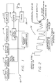
- the high definition television system of the present invention includes a transmitter section 10 and a compatible receiver section 30.
- An illustrative implementation of the transmitter section 10 is provided in Fig. 1.
- the transmitter section 10 includes a conventional high resolution camera 12 or other suitable source of high definition TV data.
- Image data from the camera 12 is provided to a logic module 14.
- the logic module 14 digitizes the image data and distributes the data into a buffer memory 16.
- the intensity of each pixel is represented by one byte (8 bits) of data.
- the logic module 14 may be implemented by a microprocessor or discrete logic in a manner known to those of ordinary skill in the art.
- the buffer memory 16 may be implemented as a dual port memory to facilitate simultaneous read/write operations.
- a compressor 18 samples all lines in the buffer memory 16 and puts compressed information in the buffer 22. This sparse data together with the full data from odd numbered lines will later be used to reconstruct the even numbered lines.
- the compressor 18 works on adjacent pixels of the complete picture to derive compressed data for the even numbered lines.
- the compressor 18 next thresholds the P data and outputs a "0" if the threshold is not exceeded and 1/16 of the value of the pixel, roughly proportional to the intensity thereof, if the threshold is exceeded.
- a preponderance of zeros will be output resulting in a compact coding scheme.
- the rough proportionality only 4 bits instead of 6 or 8, would create artificial abrupt intensity edges in the reproduced image except that the reconstruction process smoothly fills in between the transmitted pixels. Thus abrupt continuous edges are inhibited though isolated abrupt pixels may occur.
- the 4 bit pixels are stacked to 8 bit bytes and output to the buffer 22. The distribution of zeros is run length coded and placed at the end of buffer 22.
- the lower two bits of sequences of three 8-bit pixels of the odd numbered lines are replaced in sequence by the second, third, and fourth pairs of bits from the fourth pixel following the sequence of three pixels.
- the number of pixels in the line will be reduced to 3/4 of the number produced by the high definition TV camera and stored in buffer 20.
- These remaining pixels will be compatible with the present NTSC standard.
- Their lower two bits will not be noticed in usual TV lighting conditions but will be re-assembled in new receivers (equipped with the system of the present invention) to produce lines approximately 33% longer than the NTSC standard.
- the modulated color carrier will be added to the intensity data in buffer 20 to complete the NTSC standard video signal.
- the NTSC buffer 20 stores typical NTSC like data (e.g.
- a gate 24 with associated logic scans each of the buffers 20 and 22 and outputs to a conventional television transmitter 26, with associated antenna 28, a signal of the form shown in Fig. 2.
- the transmitted signal 32 resembles a conventional NTSC signal with the exception that the transmitted signal 32 of the present invention consists of an abbreviated vertical flyback synchronization (sync) pulse 34 followed by two files, one including the compressed (decimated) video data 36 and the other including the distribution data 38. These files are included during what would otherwise be the vertical flyback interval 40.
- the decimated data is data from which the redundant data has been removed by the transmitter section 10.
- the distribution data is a run-length code establishing the placement of the decimated pixels.
- the remainder of the transmitted signal 32 is a standard NTSC color waveform, inverted so that black is up. It consists of a horizontal sync pulse 40 followed by a color burst signal 42.
- the horizontal sync pulse is a large positive pulse which initiates blanking of the horizontal retrace line.
- the color burst signal 42 typically starts a ringing oscillator and provides a phase reference for the detection of the color subcarrier signal 44 which rides on the slowly varying luminance (intensity) signal 46.
- the phase and amplitude of the color subcarrier 44 typically provides the ratio of the red (R), green (G), and blue (B) colors while the absolute value of their sum is provided by the luminance signal 46.
- Fig. 3 shows an illustrative implementation of a high definition television receiver 30 designed in accordance with the principles of the present invention to decode and utilize the high definition information provided by the transmitter 10 of the form of that shown in Fig. 2.
- the signal is received by a conventional antenna 50 and processed by a standard TV tuner 52.
- the tuner 52 provides the vertical sync signal to logic module 54 with the video signal.
- the logic module 54 uses the video sync signal and the distribution data to distribute the video data into a double precision buffer memory 56.
- the run length code in the distribution data is used by the logic module 54 to establish the placement of the decimated pixels.
- the odd numbered lines are expanded by assembling the lowest two bits of three successive pixels into a fourth, 6 bit pixel.
- the logic module 54 splits the decimated video from the original video and normalizes it by multiplying it by 16.
- the distribution data 38 sets the normalized even line pixels into their proper places in buffer 56 filling the remaining positions in the even line with average values from nearby normalized pixels.
- the logic module 54 may be implemented by discrete logic or by a microprocessor as is known in the art.
- the logic module could be implemented with an analog-to-digital converter to digitize the input video signals and a counter and shift register to develop addresses for random access memory of the memory 56 from the vertical sync pulses.
- Data in the buffer memory 56 is operated on by an improvement operator 58, which in the preferred embodiment, includes a microprocessor utilizing a Poisson picture processing (PPP) algorithm.
- PPP Poisson picture processing
- the Poisson picture processing algorithm is known in the art. See the final report on ACMP DATA COMPRESSION by the Hughes Aircraft, Support Systems by J. Drummond, J. McWaid, F. Lin, and K. Dubbs, December 1985 to October 1987.
- the invention is not limited to the use of any particular algorithm or technique used to decompress the data.
- the improvement operator solves the homogeneous form of equation 1 above for the intensity values between normalized pixel data which together with pixel values on adjacent odd numbered lines provide the boundary conditions.
- the PPP iteration algorithm is complete after 6 iterations per frame in the preferred embodiment regenerating the missing pixels using both original data and the remaining decimated data.
- Data in the buffer memory 56 which may be a two part memory, is then scanned by a scanning monitor 60 for presentation in a conventional manner.
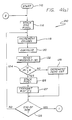
- Figs. 4(a) and 4(b) provide a flow diagram 100 of an illustrative implementation of the PPP algorithm utilized for compression of the even-numbered lines in the preferred embodiment of the present invention.
- the Start, 110 initiates processing of row two held in buffer 18.
- the left end pixel is divided by 16 and stored in the lower nibble of a byte or, on successive data coming from the loop 2, it may be stored in the upper nibble if the lower one is full. Whenever the upper nibble is filled, the byte is transferred to the storage buffer 22.
- the next pixel in row two is now examined.
- the Increment Column, step 118 increments the address to point to this pixel.
- the Convolve, step 120 forms the Laplacian, P of equation [1] using the current pixel and pixels left and right of the current pixel in the even-numbered row and the pixels above and below it in odd numbered rows.
- the threshold is computed at the Reset Threshold, step 122.
- the threshold is set high at first, but as the column counter is further incremented, the threshold is lowered in proportion to the column number until it is exceeded by the value of P at some column.
- the threshold is then re-set to its high initial value and again steadily decreased with column number.
- the present magnitude of P is compared with W.
- step 124 If, at step 124 the magnitude of P (
- the right end pixel will be stacked and the row number incremented twice at Stack End Pixel Double Increment Row, step 130. If, at End of Rows, step 132, the row number is less than 960 then the process repeats from 2. Otherwise the array of distribution data is stacked in nibbles. This is possible because the run length of zeros is kept less than 16 by the threshold adjuster 122. This adjuster also sets initial thresholds so that at least one zero follows any non-zero return.
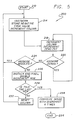
- Fig. 5 is a flow diagram 200 of an illustrative implementation of the decompression scheme utilized in the present invention.
- the Start 210 initiates processing of row two data which arrives during the vertical retrace intervals and is locally stored within the logic module.
- the first (or next) byte is unstacked by the Unstack and Store Negative True Value Increment Column, step 214.
- the lower (or next) nibble is multiplied by 512 and stored in the double precision buffer 56 as the N+1 succeeding column pixel values by the Unstack and Store Negative True Value Increment Column step 214; Increment Column Decrement Zero Cnt.
- the first of this array of pixels is stored as negative to mark it not to be changed later by the improvement operator.
- the column counter is compared with the maximum number of columns. If less than the maximum, the foregoing procedure is restarted, otherwise by the Unstack End Pixel Double Increment Row step 226, the nibble corresponding to the right end column is multiplied by 256 and set into the buffer 56 and the row counter is double incremented.
- the row counter is compared with 960 by the Is This The Last Row step 228.
- the column counter is reset and the process restarted at the Unstack and Store step 214 as described above. Otherwise the improvement operator 58 is enabled at a Convolve Image With Overshoot 6 Times step 234.
- This operator contains an iterative solver of Laplace's equation (the homogeneous form of Equation [1]). This operator uses one of the many over-relaxation procedures well known in the numerical processing literature. The preferred embodiment employs a very fast form of the algorithm as fully documented in the above-referenced final report. Three double passes are sufficient for good restoration and, in the preferred embodiment, can be accomplished in 1/30 second.
- the scanning monitor 60 is fed bits 8 - 13 from the buffer 56 pixels in a linear (not interlaced) pattern of all rows.
- the buffer 56 is a double precision buffer to speed up the operation of the improvement operator and to make it more accurate.
- the present invention has been disclosed herein with reference to a particular embodiment for a particular application. Those of ordinary skill in the art will recognize additional modifications, applications and embodiments within the scope of the invention.
- the invention is not limited to the manner by which data is written into memory.
- the invention is not limited to the techniques used to compress and decompress data.
- the invention is not limited to a particular technique for transmitting, receiving and displaying data.
Priority Applications (1)
| Application Number | Priority Date | Filing Date | Title |
|---|---|---|---|
| EP94103003A EP0608003A1 (de) | 1988-08-29 | 1989-08-14 | Hochauflösendes Fernsehsystem |
Applications Claiming Priority (2)
| Application Number | Priority Date | Filing Date | Title |
|---|---|---|---|
| US237807 | 1988-08-29 | ||
| US07/237,807 US4916525A (en) | 1988-08-29 | 1988-08-29 | High definition TV system |
Related Child Applications (2)
| Application Number | Title | Priority Date | Filing Date |
|---|---|---|---|
| EP94103003.3 Division-Into | 1989-08-14 | ||
| EP94103003A Division EP0608003A1 (de) | 1988-08-29 | 1989-08-14 | Hochauflösendes Fernsehsystem |
Publications (2)
| Publication Number | Publication Date |
|---|---|
| EP0357281A2 true EP0357281A2 (de) | 1990-03-07 |
| EP0357281A3 EP0357281A3 (de) | 1990-09-19 |
Family
ID=22895274
Family Applications (2)
| Application Number | Title | Priority Date | Filing Date |
|---|---|---|---|
| EP94103003A Withdrawn EP0608003A1 (de) | 1988-08-29 | 1989-08-14 | Hochauflösendes Fernsehsystem |
| EP19890308226 Ceased EP0357281A3 (de) | 1988-08-29 | 1989-08-14 | Hochauflösendes Fernsehsystem |
Family Applications Before (1)
| Application Number | Title | Priority Date | Filing Date |
|---|---|---|---|
| EP94103003A Withdrawn EP0608003A1 (de) | 1988-08-29 | 1989-08-14 | Hochauflösendes Fernsehsystem |
Country Status (7)
| Country | Link |
|---|---|
| US (1) | US4916525A (de) |
| EP (2) | EP0608003A1 (de) |
| JP (1) | JPH02113689A (de) |
| KR (1) | KR920009072B1 (de) |
| BR (1) | BR8904206A (de) |
| IL (1) | IL91266A (de) |
| TR (1) | TR24987A (de) |
Cited By (2)
| Publication number | Priority date | Publication date | Assignee | Title |
|---|---|---|---|---|
| EP0423690A2 (de) * | 1989-10-16 | 1991-04-24 | Hughes Aircraft Company | Schneller Bilddecodierer |
| SG81864A1 (en) * | 1990-06-01 | 2001-07-24 | Tmomson Consumer Electronics I | Chrominance processing system |
Families Citing this family (10)
| Publication number | Priority date | Publication date | Assignee | Title |
|---|---|---|---|---|
| JP2531534B2 (ja) * | 1989-05-26 | 1996-09-04 | 三菱電機株式会社 | 表示装置 |
| US5345272A (en) * | 1990-06-01 | 1994-09-06 | Thomson Consumer Electronics, Inc. | Delay matching for video data during expansion and compression |
| US5121208A (en) * | 1990-10-19 | 1992-06-09 | Zenith Electronics Corporation | Method and apparatus for reducing co-channel interference in an HDTV receiver |
| US5396343A (en) * | 1991-03-14 | 1995-03-07 | Nec Electronics, Inc. | Image compresssion systems with optimized data access |
| US5182594A (en) * | 1991-10-09 | 1993-01-26 | Hopson Talmadge W | CRT method of and apparatus for illuminating photographic negatives to produce a hard copy |
| US5305104A (en) * | 1992-07-27 | 1994-04-19 | The Trustees Of Columbia University In The City Of New York | Digitally assisted motion compensated deinterlacing for enhanced definition television |
| US5631979A (en) * | 1992-10-26 | 1997-05-20 | Eastman Kodak Company | Pixel value estimation technique using non-linear prediction |
| JP3334021B2 (ja) * | 1994-10-26 | 2002-10-15 | オムロン株式会社 | 画像処理方法およびその方法を用いた画像処理システム |
| US8479241B2 (en) * | 2007-05-10 | 2013-07-02 | At&T Intellectual Property I, Lp | System and method to control communication of data |
| WO2009128798A1 (en) * | 2008-04-16 | 2009-10-22 | Nikon Corporation | Method for deblurring an image that produces less ringing |
Citations (2)
| Publication number | Priority date | Publication date | Assignee | Title |
|---|---|---|---|---|
| WO1985000492A1 (en) * | 1983-07-08 | 1985-01-31 | Independent Broadcasting Authority | Extended definition television system |
| JPS60191562A (ja) * | 1984-03-13 | 1985-09-30 | Konishiroku Photo Ind Co Ltd | 画像処理装置 |
Family Cites Families (6)
| Publication number | Priority date | Publication date | Assignee | Title |
|---|---|---|---|---|
| GB505653A (en) * | 1937-10-11 | 1939-05-11 | Scophony Ltd | Improvements in or relating to television and the like systems |
| GB2115641B (en) * | 1982-02-24 | 1986-08-06 | Rca Corp | Compatible high definition television system |
| US4707728A (en) * | 1982-02-24 | 1987-11-17 | Rca Corporation | Compatible HDTV with increased vertical and horizontal resolution |
| US4882614A (en) * | 1986-07-14 | 1989-11-21 | Matsushita Electric Industrial Co., Ltd. | Multiplex signal processing apparatus |
| JPS6386987A (ja) * | 1986-09-30 | 1988-04-18 | Matsushita Electric Ind Co Ltd | テレビジョン信号送受信装置 |
| GB2203011A (en) * | 1987-03-26 | 1988-10-05 | British Broadcasting Corp | Transmitting television signals |
-
1988
- 1988-08-29 US US07/237,807 patent/US4916525A/en not_active Expired - Lifetime
-
1989
- 1989-08-09 IL IL9126689A patent/IL91266A/en not_active IP Right Cessation
- 1989-08-14 EP EP94103003A patent/EP0608003A1/de not_active Withdrawn
- 1989-08-14 EP EP19890308226 patent/EP0357281A3/de not_active Ceased
- 1989-08-22 BR BR898904206A patent/BR8904206A/pt not_active Application Discontinuation
- 1989-08-24 TR TR89/0854A patent/TR24987A/xx unknown
- 1989-08-28 KR KR1019890012239A patent/KR920009072B1/ko not_active IP Right Cessation
- 1989-08-29 JP JP1220494A patent/JPH02113689A/ja active Pending
Patent Citations (2)
| Publication number | Priority date | Publication date | Assignee | Title |
|---|---|---|---|---|
| WO1985000492A1 (en) * | 1983-07-08 | 1985-01-31 | Independent Broadcasting Authority | Extended definition television system |
| JPS60191562A (ja) * | 1984-03-13 | 1985-09-30 | Konishiroku Photo Ind Co Ltd | 画像処理装置 |
Non-Patent Citations (2)
| Title |
|---|
| 15TH INTERNATIONAL T.V. SYMPOSIUM, Montreux, 11th - 17th June 1987, Symposium Record, Broadcast Sessions, pages 45-54; Y. SI-LE et al.: "A compatible enhanced quality television system (HBVL system)" * |
| PATENT ABSTRACTS OF JAPAN, vol. 10, no. 35 (E-380)2092], 12th February 1986; & JP-A-60 191 562 (KONISHIROKU SHASHIN KOGYO K.K.) 30-09-1985 * |
Cited By (4)
| Publication number | Priority date | Publication date | Assignee | Title |
|---|---|---|---|---|
| EP0423690A2 (de) * | 1989-10-16 | 1991-04-24 | Hughes Aircraft Company | Schneller Bilddecodierer |
| EP0423690A3 (en) * | 1989-10-16 | 1993-11-18 | Hughes Aircraft Co | Fast image decoder |
| US5414804A (en) * | 1989-10-16 | 1995-05-09 | Hughes Aircraft Company | Fast image decoder |
| SG81864A1 (en) * | 1990-06-01 | 2001-07-24 | Tmomson Consumer Electronics I | Chrominance processing system |
Also Published As
| Publication number | Publication date |
|---|---|
| EP0608003A1 (de) | 1994-07-27 |
| BR8904206A (pt) | 1990-04-10 |
| IL91266A0 (en) | 1990-03-19 |
| JPH02113689A (ja) | 1990-04-25 |
| IL91266A (en) | 1994-05-30 |
| EP0357281A3 (de) | 1990-09-19 |
| US4916525A (en) | 1990-04-10 |
| TR24987A (tr) | 1992-08-17 |
| KR920009072B1 (ko) | 1992-10-13 |
| KR900004201A (ko) | 1990-03-27 |
Similar Documents
| Publication | Publication Date | Title |
|---|---|---|
| KR100336250B1 (ko) | 디지탈비디오신호처리시스템용온스크린디스플레이장치 | |
| US5457499A (en) | Source adaptive television system | |
| US5557298A (en) | Method for specifying a video window's boundary coordinates to partition a video signal and compress its components | |
| CA1327394C (en) | Edtv system | |
| Ciciora | Twenty-Four Rows of Videotex in 525 Scan Lines | |
| US6489997B1 (en) | Versatile video transformation device | |
| KR100375800B1 (ko) | Mpeg영상신호처리시스템용애니메이션osd장치 | |
| US4916525A (en) | High definition TV system | |
| US5170256A (en) | Image display system for displaying picture with smaller aspect ratio on large-aspect-ratio screen of television receiver | |
| EP0711486B1 (de) | Verfahren und gerät zur digitalen aufzeichnung von einem hochauflösenden bildschirm | |
| US5032907A (en) | Video panning system for widescreen television | |
| JP2882584B2 (ja) | 既存テレビジョン放送方法と互換性のあるワイドスクリーンテレビジョン放送方法 | |
| US5850264A (en) | Pseudo interlacing in digital video | |
| EP0781493B1 (de) | Paketiertes yuv9 format zur verschachtelten speicherung und effizienten bearbeitung von digitalen videodaten | |
| EP0083352B1 (de) | Farbfernsehsystem | |
| US6751256B1 (en) | Transmission of digital images within the NTSC analog format | |
| EP0103488A2 (de) | Verfahren und Vorrichtung zur Kodierung und Dekodierung eines Videosignals | |
| EP0451205B1 (de) | Mit herkömmlichen fernsehnormen kompatibles fernsehübertragungssystem | |
| JPS62256581A (ja) | 互換性ワイド・スクリ−ン・テレビジヨン信号発生装置 | |
| US5278649A (en) | Method and apparatus for transmission of signals for an extended definition television system | |
| CN1018139B (zh) | 具有另一种副载波的视频信号处理器 | |
| JP2646132B2 (ja) | テレビジョン受像機 | |
| CN108989849A (zh) | 一种dvb-t2+s2电视信号处理方法及系统 | |
| CN1094210A (zh) | 管理的字幕区显示 | |
| JPS5852390B2 (ja) | テレビジヨン画像信号伝送方式 |
Legal Events
| Date | Code | Title | Description |
|---|---|---|---|
| PUAI | Public reference made under article 153(3) epc to a published international application that has entered the european phase |
Free format text: ORIGINAL CODE: 0009012 |
|
| AK | Designated contracting states |
Kind code of ref document: A2 Designated state(s): CH DE FR GB IT LI SE |
|
| PUAL | Search report despatched |
Free format text: ORIGINAL CODE: 0009013 |
|
| AK | Designated contracting states |
Kind code of ref document: A3 Designated state(s): CH DE FR GB IT LI SE |
|
| 17P | Request for examination filed |
Effective date: 19910225 |
|
| 17Q | First examination report despatched |
Effective date: 19930423 |
|
| STAA | Information on the status of an ep patent application or granted ep patent |
Free format text: STATUS: THE APPLICATION HAS BEEN REFUSED |
|
| 18R | Application refused |
Effective date: 19950119 |