EP0356942B1 - Panneaux de distribution des 1550 nm fibres - Google Patents
Panneaux de distribution des 1550 nm fibres Download PDFInfo
- Publication number
- EP0356942B1 EP0356942B1 EP89115730A EP89115730A EP0356942B1 EP 0356942 B1 EP0356942 B1 EP 0356942B1 EP 89115730 A EP89115730 A EP 89115730A EP 89115730 A EP89115730 A EP 89115730A EP 0356942 B1 EP0356942 B1 EP 0356942B1
- Authority
- EP
- European Patent Office
- Prior art keywords
- opposing
- panel
- guides
- housing
- extending
- Prior art date
- Legal status (The legal status is an assumption and is not a legal conclusion. Google has not performed a legal analysis and makes no representation as to the accuracy of the status listed.)
- Expired - Lifetime
Links
- 239000000835 fiber Substances 0.000 title description 33
- 239000013307 optical fiber Substances 0.000 claims description 49
- 238000003491 array Methods 0.000 claims 1
- 230000003287 optical effect Effects 0.000 description 11
- 238000005452 bending Methods 0.000 description 3
- 230000005540 biological transmission Effects 0.000 description 3
- 230000008520 organization Effects 0.000 description 2
Images


Classifications
-
- G—PHYSICS
- G02—OPTICS
- G02B—OPTICAL ELEMENTS, SYSTEMS OR APPARATUS
- G02B6/00—Light guides; Structural details of arrangements comprising light guides and other optical elements, e.g. couplings
- G02B6/44—Mechanical structures for providing tensile strength and external protection for fibres, e.g. optical transmission cables
- G02B6/4439—Auxiliary devices
- G02B6/444—Systems or boxes with surplus lengths
- G02B6/4452—Distribution frames
- G02B6/44526—Panels or rackmounts covering a whole width of the frame or rack
-
- G—PHYSICS
- G02—OPTICS
- G02B—OPTICAL ELEMENTS, SYSTEMS OR APPARATUS
- G02B6/00—Light guides; Structural details of arrangements comprising light guides and other optical elements, e.g. couplings
- G02B6/44—Mechanical structures for providing tensile strength and external protection for fibres, e.g. optical transmission cables
- G02B6/4439—Auxiliary devices
- G02B6/444—Systems or boxes with surplus lengths
- G02B6/44528—Patch-cords; Connector arrangements in the system or in the box
-
- G—PHYSICS
- G02—OPTICS
- G02B—OPTICAL ELEMENTS, SYSTEMS OR APPARATUS
- G02B6/00—Light guides; Structural details of arrangements comprising light guides and other optical elements, e.g. couplings
- G02B6/44—Mechanical structures for providing tensile strength and external protection for fibres, e.g. optical transmission cables
- G02B6/4439—Auxiliary devices
- G02B6/444—Systems or boxes with surplus lengths
- G02B6/4453—Cassettes
- G02B6/4454—Cassettes with splices
-
- G—PHYSICS
- G02—OPTICS
- G02B—OPTICAL ELEMENTS, SYSTEMS OR APPARATUS
- G02B6/00—Light guides; Structural details of arrangements comprising light guides and other optical elements, e.g. couplings
- G02B6/44—Mechanical structures for providing tensile strength and external protection for fibres, e.g. optical transmission cables
- G02B6/4439—Auxiliary devices
- G02B6/444—Systems or boxes with surplus lengths
- G02B6/4453—Cassettes
- G02B6/4455—Cassettes characterised by the way of extraction or insertion of the cassette in the distribution frame, e.g. pivoting, sliding, rotating or gliding
Definitions
- the present invention relates to apparatus for selectively interfacing optical fibers with second optical fibers in accordance with the generic clause of claim 1. That is, outside plant fiber optical cable with optical fibers of internal; that is, inside plant fiber optical cable.
- the present invention relates to interfacing external fiber optical cable with internal fiber optical cable connected to telephone transmission equipment.
- the apparatus serves an an integrated connector panel, splice shelf and cable storage unit for interconnection between outside plant cable and fiber optic testing, multiplexing and transmission equipment.
- Such an apparatus is already known from document EP-0 215 668, which describes an apparatus including a housing having a plurality of trays swingable from a storage position inside the housing to an access position in front of the housing.
- the housing also carries a drawer, whereby all connections between fibers of a trunk cable and the fibers of a pigtail cable are made in the drawer.
- connectors are provided which are positioned within said housing for optically connecting an end of said second optical fibers to a corresponding second end of respective pigtails of said plurality of pigtails.
- a stationary housing includes a moveable splice tray and cable storage unit wherein attenuation is not a problem and optical fiber bending is controlled.
- interfacing apparatus which can be mounted in standard equipment containing optical fiber, or upon a wall or the like.
- the invention achieves these and other results by providing apparatus for selectively interfacing first optical fibers with second optical fibers in accordance with the characterizing features of claim 1.
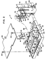
- Figures 1 and 2 depict an apparatus 2 for interfacing first optical fibers 4 of at least one first fiber optical cable 6 such as an external optical cable with second optical fibers 8 (not seen in Figure 1) in the form of, for example, respective internal jumper patch cords.
- first fiber optical cable 6 such as an external optical cable
- second optical fibers 8 not seen in Figure 1
- the apparatus 2 is useful in interfacing outside plant cable 6 with inside plant cords 10 connected to telephone transmission equipment, not shown.
- the apparatus 2 includes a housing comprising a base 12 and an opposing top 14. First opposing side wall 16 and second opposing side wall 18 are also provided extending vertically from base 12 to top 14. A rear wall 20 depicted in Figures 3 and 4 extends vertically from base 12 to top 14 and from first opposing side wall 16 to second opposing side wall 18. A forward opening 22 is provided opposite real wall 20. Means associated with the first and second side walls are provided for slideably supporting a drawer within the housing so that the drawer can be slid relative to the rear wall into the housing and out of the housing at the forward opening. For example, tracks 24 and 26 are provided in a known manner to facilitate such movement of a drawer 28.
- Drawer 28 is provided for sliding upon the slideably supporting means such as tracks 24 and 26.
- Drawer 28 forms an enclosure 30 including a bottom 32, first opposing side panel 34 and second opposing side panel 36 each extending vertically from bottom 32, a rear panel 38 including two sections extending vertically from bottom 32, and a front panel 40 opposite the rear panel 38 and extending vertically from bottom 32 and extending from the first opposing side wall 34 to the second opposing side wall 36.
- First means are positioned within the housing for storing the second optical fiber 8.
- such first means includes a plurality of removable cassettes 42.
- the housing includes a first plurality of opposing guides 44, 46 for guiding respective removable cassettes 42 into and out of the housing.
- Respective opposing guides 44, 46 are depicted as providing sets of tracks for the cassettes 42 to slide upon, respective pairs of tracks 44, 46 being stacked vertically towards the top 14, and extending towards the rear wall 20, of apparatus 2.
- the first plurality of opposing guides 44, 46 are positioned towards a side of the housing adjacent the first opposing wall 16.
- the housing also preferably includes a second plurality of opposing guides 48, 50 for guiding additional respective removable cassettes 42 into and out of the housing.
- Respective opposing guides 48, 50 are identical to guides 44, 46.
- respective opposing guides 48, 50 are depicted as providing sets of tracks for the additional cassettes 42 to slide upon, respective pairs of tracks 48, 50 also being stacked vertically towards the top 14, and extending towards the rear wall 20, of apparatus 2.
- the second plurality of opposing guides 48, 50 are positioned towards a side of the housing adjacent the second opposing wall 18.
- each respective cassette 42 includes opposing sides 52, 54 which slide upon respective of the opposing guides 44, 46 and 48, 50.
- each cassette 42 includes a rear edge 56 having a catch-like protuberance 58 extending therefrom.
- a rear abutment 58 is provided extending between respective opposing guides 44, 46 and between respective opposing guides 48, 50.
- Such rear abutment 58 includes a first plurality of apertures 60 each of which is positioned between a respective pair of opposing guides 44, 46.
- apertures 60 are centered between respective guides 44, 46 as depicted in Figure 4 so that when a cassette 42 is guided into the housing by sliding the cassette upon a pair of opposing guides, the catch-like protuberance 58 of such cassette will be received by the respective aperture 60 to lock the cassette in place.
- a similar second plurality of apertures 62 is provided each being positioned between a respective pair of opposing guides 48, 50 to receive a protuberanced 58 of a cassette 42 which is guided into the housing by sliding upon a pair of opposing guides 48, 50, in a like manner.
- each cassette 42 includes a hub 64 having flanges 66 and includes two pairs of spaced bosses 68, 70 each of which is designed in a known manner to pinch an optical fiber therebetween.
- Such structure allows an optical fiber 8 to be wound about hub 64 to take up fiber slack and be held firmly in place by bosses 68, 70.
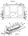
- Second means are provided positioned within the enclosure 30 for storing the first optical fibers and for storing a plurality of pigtails.
- such second means includes a first divider 72 which extends vertically from bottom 32, is parallel to rear panel 38, and is positioned midway between front panel 40 and rear panel 38.
- First opposing side panel 34 and second opposing side panel 36 include respective upper edges 74 and 76 spaced from the bottom 32 and having respective first opposing flanges 78 and 80 extending therefrom generally parallel to base 32 as depicted in Figure 1.
- the rear panel which preferably is in the form of two sections 38, and the first divider 72, each include respective upper edges 82 and 84 spaced from bottom 32 and having respective second opposing flanges 86 and 88 extending therefrom.
- such second means also includes a second divider 90 which extends vertically from bottom 32, is parallel to the rear panel 38, and is positioned between the rear panel 38 and the first divider 72.
- the bottom 32 includes a first aperture 92 positioned in an area adjacent the first opposing side panel 34 and a second aperture 96 positioned in an area adjacent the second opposing side panel 36.
- a third means is provided positioned within the enclosure 30 for splicing an end of respective of the first optical fibers 4 to a corresponding first end of respective pigtails which are provided as described herein.
- such third means includes at least one splice tray 106.
- Such splice tray is attached to the bottom 32 of the drawer 28 in an area between the front panel and the first divider 72.
- the first divider extends from the first opposing side panel 34 towards the second opposing side panel 36, the first divider 72 being spaced from the second opposing side panel 36 at 108 to provide an area through which fibers 4 and the pigtails can extend to the splice tray 106.
- the splice tray 106 is attached to the drawer 28 by bolts 110 which extend vertically from bottom 32 of the drawer through apertures 112 in the splice tray 106 which is then held in place by nuts 114.
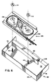
- a plurality of similar splice trays can be stacked upon one another when required as depicted in Figure 6.
- Apparatus 2 includes fourth means positioned within the housing for optically connecting an end of respective of the second optical fibers 8 to a corresponding second end of respective pigtails provided as described herein.
- fourth means includes connector panels 116 which are positioned between the first plurality of opposing guides 44, 46 and the second plurality of opposing guides 48, 50 as depicted in Figure 4, connector panels 116 being held in place by means of screws 118.
- Each connector panel includes a plurality of apertures 120 extending therethrough.
- Means are provided attached to each connector panel for optically connecting second optical fibers 8 to respective second ends of respective pigtails as described herein.
- adapters or attenuators of a type known in the art and generally depicted at 122 are provided into which the second optical fiber 8 and the pigtails can be plugged in a known manner.
- the outer sheath of cable 6 is stripped therefrom in a known manner to expose the buffered fibers 4 and strength member 4′. Subsequently the fibers 4, strength member 4′, and cable 6 are inserted through a clamping member 124 positioned at second opposing side 18 and clamped firmly in place.
- the strength member 4′ is then secured to a tie-off 126 in a known manner and the fibers 4 are routed through a cable entry 128, which extends through side 18, and onto to the drawer 28 via the entrance aperture 92, the fibers 4 being secured by tie wraps 130 as desired and the slack being taken up by wrapping the fibers 4 generally circularly in a counter-clockwise direction viewing Figure 2 within the confirms of flanges 78, 80, 86 and 88.
- the apparatus 2 can be provided with corresponding hardware and a second cable entry aperture 128 at the first opposing side 16 to increase the flexibility of the apparatus. Fibers extending from cable fastened at side 16 should be passed through entrance aperture 96. In other words, preferably the entrance aperture located on the side of the apparatus opposite the cable entry port is the one used to route fibers.
- Fiber optical cables known as pigtails serve to bridge first optical fibers 4 and second optical fibers 8.
- a pigtail 132 is provided for each first fiber 4 to be connected to a corresponding second fiber 8.
- Each pigtail 132 includes a first end 134 and a second end 136. As depicted in Figure 7, each end 136 is connected to an adapter or attenuator 122 at the rear of the connector panel 116 in a known manner.
- Each pigtail 132 is then routed onto drawer 28 via entrance aperture 92, the pigtails 132 being secured by tie wraps 130 as desired and the slack being taken up by wrapping the pigtails generally circularly in a clockwise direction viewing Figure 2 within the confines of flanges 78, 80, 86 and 88.
- Each fiber 4 and pigtails 132 are then routed as depicted in Figures 2 and 6 through the space provided at 108, wrapped about take-up hubs 138 in a manner allowing fiber 4 and pigtail 132 to be optically coupled at a splice 140 in a known manner.
- each jumper patch cord includes an end 10 which is connected to the adapter or attenuator 122 at the front of the connector panel 116 in a known manner.
- a cover 142 is mounted upon drawer 28 by screws 144 and the drawer is closed. Then the front cover 146 is closed as depicted in Figure 3 and locked in place.
- front cover 146 is removably hinged to the top of the housing in a known manner at hinges 148 which are positioned adjacent the forward opening of the housing.
- the first opposing side wall 16 and the second opposing side wall 18 can each include a plurality of optical fiber apertures in the form of cable entry ports 128. In this manner, access can be provided at the front of apparatus 2 or at the rear of apparatus 2 through an aperture in a respective opposing side wall.
- a fifth means can be provided removably attached to the first and second opposing side walls 16, 18 for preventing damage to any optical fibers extending through any of the apertures 128.
- fiber guards 150 can be attached to walls 16 and 18 in the vicinity of whatever aperture 128 is being used, by screwing the fiber guard to a mounting angle 152 by means of screws 154.
- Adjustable mounting brackets 156 are provided so that by removing screws 158 the brackets 156 can be positioned to accommodate various sizes of equipment or to accommodate a wall mounting.
- the apparatus of the present invention provides a means by which internal or inside optical fibers can be optically coupled to external or outside optical fibers using equipment which allows for testing and servicing from the front of apparatus which includes a stationary housing and moveable splice tray and cable storage unit. Optical fiber bending is controlled and attenuation is not a problem.
- the apparatus of the present invention is compact and can be mounted in standard equipment or upon a wall or the like, and yet is readily accessible. Fiber organization is improved so that users can access specific fibers quickly and easily with less risk of breakage and improved productivity.
Landscapes
- Physics & Mathematics (AREA)
- General Physics & Mathematics (AREA)
- Optics & Photonics (AREA)
- Light Guides In General And Applications Therefor (AREA)
- Mechanical Coupling Of Light Guides (AREA)
- Cable Accessories (AREA)
Claims (15)
- Appareil pour interfacer sélectivement des premières fibres optiques (4) et des secondes fibres optiques (8) comprenant :
un boîtier présentant un fond (12) et un sommet opposé (14), des première et deuxième parois latérales opposées (16, 18) faisant saillie orthogonalement du dit fond (12) jusqu'au dit sommet (14), une paroi arrière s'étendant orthogonalement du dit fond (12) jusqu'au dit sommet (14) et s'étendant de la dite première paroi latérale opposée jusqu'à la dite deuxième paroi latérale opposée (20), une ouverture frontale (22) opposée à la dite paroi arrière (18), et un moyen (24, 26) associé aux dites première et deuxième parois latérales pour porter de façon coulissante un tiroir (28) à l'intérieur du dit boîtier, de telle manière que le dit tiroir puisse coulisser par rapport à la dite paroi arrière dans le dit boîtier et hors du dit boîtier par l'intermédiaire de la dite ouverture avant ;
un tiroir (28) coulissant par rapport au dit moyen de support coulissable, le dit tiroir formant une enceinte incluant un fond (32), des premier et deuxième panneaux latéraux opposés (34, 36) faisant saillie orthogonalement du dit fond (32), un panneau arrière (38) faisant saillie orthogonalement du dit fond (32), et un panneau frontal (40) opposé au dit panneau arrière et faisant saillie orthogonalement du dit fond (32), le dit tiroir s'étendant du dit premier panneau latéral opposé (34) jusqu'au dit deuxième panneau latéral (36) ;
un premier moyen (42, 44, 46) disposé à l'intérieur du dit boîtier pour emmagasiner les dites secondes fibres optiques (8) ;
un deuxième moyen (72, 90) disposé à l'intérieur du dit tiroir pour emmagasiner les dites premières fibres optiques (4) et pour emmagasiner une pluralité de connexions toronnées (132) ;
un troisième moyen (106) disposé à l'intérieur du dit tiroir pour raccorder une première extrémité de chacune des dites premières fibres optiques (4) à une première extrémité correspondante d'une différente des dites connexions toronnées (32) ;
un quatrième moyen (116) pour connecter optiquement une deuxième extrémité de chacune des dites secondes fibres optiques (8) à une deuxième extrémité correspondante d'une différente des dites connexions toronnées (132);
caractérisé en ce que
le dit premier moyen (42) comprend une pluralité cassettes amovibles par coulissement et au moins une première pluralité de paires opposées de guides (44, 46) pour guider de façon coulissante la dite pluralité de cassettes amovibles (42) dans et hors du dit boîtier par rapport aux dits guides associés opposés (44, 46) de la dite première pluralité de guides opposés qui sont disposés en deux rangées parallèles séparées, chaque rangée faisant saillie dans une direction orthogonale au dit sommet (14), chaque guide s'étendant vers la dite paroi arrière (20) ;
le dit troisième moyen comprend au moins un plateau de jonction (106) fixé au dit fond (32) du dit tiroir (28) dans une zone entre le dit panneau frontal et le dit deuxième moyen (72) qui est aussi dans le tiroir ; et
le dit quatrième moyen comprend un panneau de connexion (116) disposé à l'intérieur du dit boîtier, le dit panneau de connexion (116) étant fixé contre le dit premier moyen (40, 44, 46) de façon généralement parallèle à la dite paroi arrière et de façon généralement orthogonale au dit sommet. - Appareil selon la revendication 1 dans lequel la dite première pluralité de guides opposés (44, 46) est disposée vers un côté du dit boîtier à proximité de la dite première paroi opposée (16), et une deuxième pluralité de guides opposés (48, 50) pour guider la dite pluralité de cassettes amovibles (42) à l'intérieur ou à l'extérieur du dit boîtier, les guides opposés associés (48, 50) de la dite deuxième pluralité de guides opposés (48, 50) étant empilés orthogonalement en direction du dit sommet (14) et s'étendant vers la dite paroi arrière (20), la dite deuxième pluralité de guides opposés (48, 50) étant positionnée vers un côté du dit boîtier à proximité de la dite deuxième paroi latérale opposée (18), et le panneau de connexion (116) est disposé entre les guides (48, 50).
- Appareil selon la revendication 2 dans lequel chaque cassette associée (42) de la dite pluralité de cassettes amovibles (42) présente des côtés opposés (52, 54) qui coulissent sur les guides respectifs des dits guides opposés (44, 46, 48, 50), et inclut, en outre, un bord arrière (56) présentant une protubérance de type de prise (58) qui en fait saillie, et, en outre, dans lequel le dit premier moyen (42, 44, 46) présente une butée arrière (58) faisant saillie entre les dits guides opposés associés (44, 46) de la dite première pluralité de guides opposés et entre les dits guides opposés associés (48, 50) de la dite deuxième pluralité de guides opposés, la dite butée arrière (58) présentant une première pluralité d'ouvertures (60), chaque ouverture (60) de la dite première pluralité d'ouvertures (60) étant disposée entre les guides opposés associés (44, 46) de la dite première pluralité des guides opposés pour recevoir une protubérance associée (58) de type de prise lorsqu'une cassette associée (42) de la dite pluralité de cassettes amovibles est guidée par des guides opposés associés (44, 46) de la dite première pluralité de guides opposés à l'intérieur du dit boîtier, et une deuxième pluralité d'ouvertures (62), chaque ouverture de la dite deuxième pluralité d'ouvertures (62) étant disposée entre des guides opposés associés (48, 50) de la dite deuxième pluralité de guides opposés pour recevoir une protubérance associée de type de prise (58) lorsqu'une cassette associée (42) de la dite pluralité de cassettes amovibles est guidée par les guides opposés associés (48, 50) de la dite deuxième pluralité de guides opposés à l'intérieur du dit boîtier.
- Appareil selon la revendication 1 ou 3 dans lequel le dit deuxième moyen (72, 90) inclut un premier diviseur (72) qui fait saillie orthogonalement du dit fond (32), est parallèle au dit panneau arrière (38) et est disposé entre le dit panneau frontal (40) et le dit panneau arrière (38), et, en outre, dans lequel les dits premier et deuxième panneaux latéraux opposés (34, 36) présentent des bords supérieurs respectifs (74, 76) séparés du dit fond (32) et ayant des premiers rebords opposés respectifs (78, 80) faisant saillie de ceux-ci, et le dit panneau arrière (38) et le dit premier diviseur (72) incluent des bords supérieurs respectifs (82, 84) séparés du dit fond (32) et ayant des deuxièmes rebords opposés respectifs (86, 88) faisant saillie de ceux-ci.
- Appareil selon la revendication 4 dans lequel le dit deuxième moyen (72, 90) inclut un deuxième diviseur (90) qui fait saillie orthogonalement du dit fond (32), est parallèle au dit panneau arrière (38), et est disposé entre le dit panneau arrière (38) et le dit premier diviseur (72), et, en outre, dans lequel le dit fond (32) présente une première ouverture (92) pratiquée dans une zone adjacente au dit premier panneau latéral opposé (34) et une deuxième ouverture (96) pratiquée dans une zone adjacente au dit deuxième panneau latéral opposé (36).
- Appareil selon la revendication 5 dans lequel le dit premier diviseur (72) s'étend du dit premier panneau latéral opposé (34) jusqu'au dit deuxième panneau latéral opposé (36) dont il est séparé.
- Appareil selon la revendication 2 dans lequel le dit un panneau de connexion (116) est disposé entre la dite première pluralité de guides opposés (44, 46) et la dite deuxième pluralité de guides opposés (48, 50).
- Appareil selon la revendication 7 incluant, en outre, un moyen (122) fixé au dit panneau de connexion (116) pour connecter optiquement la dite extrémité d'une respective des dites secondes fibres optiques (8) à une deuxième extrémité correspondante d'une connexion toronnée associée (132).
- Appareil selon la revendication 1 dans lequel le dit tiroir (28) comporte un couvercle (142).
- Appareil selon la revendication 1 dans lequel le dit boîtier comporte un couvercle frontal (146) articulé de façon amovible au dit sommet adjacent à la dite ouverture avant.
- Appareil selon la revendication 1 dans lequel les dites première et deuxième parois latérales opposées (16, 18) incluent chacune une pluralité d'ouvertures (128) pour des fibres optiques.
- Appareil selon la revendication 11 incluant, en outre, un cinquième moyen (150) fixé de façon amovible aux dites première et deuxième parois latérales opposées (16, 18) pour éviter d'endommager une des fibres optiques traversant n'importe laquelle de la dite pluralité d'ouvertures (128) pour des fibres optiques.
- Appareil pour interfacer sélectivement des premières fibres optiques et des secondes fibres optiques (8) selon la revendication 1, caractérisé, en outre, en ce qu'au moins une ouverture (128) pour fibres optiques traverse au moins une des dites première et deuxième parois latérales opposées (16, 18), et en ce que les dites secondes fibres optiques font saillie à l'intérieur du dit boîtier en traversant une de la dite au moins une ouverture pour fibres optiques.
- Appareil selon la revendication 13 dans lequel le dit deuxième moyen inclut un premier diviseur (72) qui fait saillie orthogonalement à partir du dit fond (32), est parallèle au dit panneau arrière (38) et est disposé entre le dit panneau frontal (40) et le dit panneau arrière (38), et, en outre, dans lequel les dites première et deuxième parois latérales opposées (34, 36) présentent des bords supérieurs respectifs (74, 76) séparés du dit fond (32) et ayant des premiers rebords opposés respectifs (78, 80) faisant saillie de ceux-ci, et le dit panneau arrière (38) et le dit premier diviseur (72) présentent des bords supérieurs respectifs (82, 84) séparés du dit fond (32) et ayant des deuxièmes rebords opposés respectifs (86, 88) faisant saillie de ceux-ci.
- Appareil selon la revendication 14 incluant, en outre, un moyen (122) fixé au dit panneau de connexion pour connecter optiquement une deuxième extrémité de chacune des dites secondes fibres à une deuxième extrémité correspondante d'une différente des dites connexions toronnées (132).
Applications Claiming Priority (2)
| Application Number | Priority Date | Filing Date | Title |
|---|---|---|---|
| US07/237,477 US4900123A (en) | 1988-08-29 | 1988-08-29 | 1550 nm fiber distribution panel |
| US237477 | 1988-08-29 |
Publications (3)
| Publication Number | Publication Date |
|---|---|
| EP0356942A2 EP0356942A2 (fr) | 1990-03-07 |
| EP0356942A3 EP0356942A3 (fr) | 1991-03-13 |
| EP0356942B1 true EP0356942B1 (fr) | 1995-01-11 |
Family
ID=22893883
Family Applications (1)
| Application Number | Title | Priority Date | Filing Date |
|---|---|---|---|
| EP89115730A Expired - Lifetime EP0356942B1 (fr) | 1988-08-29 | 1989-08-25 | Panneaux de distribution des 1550 nm fibres |
Country Status (4)
| Country | Link |
|---|---|
| US (1) | US4900123A (fr) |
| EP (1) | EP0356942B1 (fr) |
| JP (1) | JPH02111901A (fr) |
| DE (1) | DE68920511T2 (fr) |
Cited By (9)
| Publication number | Priority date | Publication date | Assignee | Title |
|---|---|---|---|---|
| US9002166B2 (en) | 2011-10-07 | 2015-04-07 | Adc Telecommunications, Inc. | Slidable fiber optic connection module with cable slack management |
| US9057859B2 (en) | 2011-10-07 | 2015-06-16 | Adc Telecommunications, Inc. | Slidable fiber optic connection module with cable slack management |
| US9075203B2 (en) | 2012-01-17 | 2015-07-07 | Adc Telecommunications, Inc. | Fiber optic adapter block |
| US9128262B2 (en) | 2013-02-05 | 2015-09-08 | Adc Telecommunications, Inc. | Slidable telecommunications tray with cable slack management |
| US9170391B2 (en) | 2011-10-07 | 2015-10-27 | Adc Telecommunications, Inc. | Slidable fiber optic connection module with cable slack management |
| US9389384B2 (en) | 2013-02-27 | 2016-07-12 | Commscope Technologies Llc | Slidable fiber optic connection module with cable slack management |
| US9541726B2 (en) | 2013-04-24 | 2017-01-10 | Adc Czech Republic, S.R.O. | Optical fiber distribution system |
| US9568699B2 (en) | 2013-01-29 | 2017-02-14 | CommScope Connectivity Belgium BVBA | Optical fiber distribution system |
| US10025054B2 (en) | 2014-07-10 | 2018-07-17 | Corning Optical Communications LLC | Optical fiber distribution hub with fiber routing structures |
Families Citing this family (180)
| Publication number | Priority date | Publication date | Assignee | Title |
|---|---|---|---|---|
| US3475480A (en) * | 1966-05-17 | 1969-10-28 | Thompson Chem Co Hayward | Synthesis of aromatic nitriles by nitrilizing halogenated intermediates |
| US5071211A (en) * | 1988-12-20 | 1991-12-10 | Northern Telecom Limited | Connector holders and distribution frame and connector holder assemblies for optical cable |
| FR2646928B1 (fr) * | 1989-05-11 | 1993-12-24 | Etat Francais Cnet | Module et boitier de raccordement de cables a fibres optiques |
| US4976510B2 (en) * | 1989-11-20 | 1995-05-09 | Siecor Corp | Communication outlet |
| GB2241591A (en) * | 1990-02-28 | 1991-09-04 | Optical Data Communications Li | Mounting frames for fibre optic or electrical cable organiser trays |
| FR2660077B1 (fr) * | 1990-03-20 | 1993-08-20 | Loh Rittal Werk Gmbh Co | Boitier de raccordement pour fibres optiques. |
| US5092663A (en) * | 1990-05-21 | 1992-03-03 | Gte North Incorporated | Apparatus and method for maintaining slack of fiber optic cable or the like |
| US5208894A (en) * | 1990-07-16 | 1993-05-04 | Adc Telecommunications, Inc. | Fiber optic splice cabinet |
| EP0501336B1 (fr) * | 1991-02-27 | 1996-06-05 | Siemens Aktiengesellschaft | Boîtier de séparation de fibres optiques |
| US5434944A (en) * | 1991-06-18 | 1995-07-18 | British Telecommunications Public Limited Company | Optical fibre connection equipment |
| US5204929A (en) * | 1991-09-04 | 1993-04-20 | Reliance Comm/Tec Corporation | Fiber patch panel |
| US5247603A (en) * | 1992-01-24 | 1993-09-21 | Minnesota Mining And Manufacturing Company | Fiber optic connection system with exchangeable cross-connect and interconnect cards |
| US5243679A (en) * | 1992-02-07 | 1993-09-07 | Gv Medical, Inc. | Optical fiber advancement, retraction and storage system |
| US5363467A (en) * | 1993-05-28 | 1994-11-08 | Minnesota Mining And Manufacturing Company | Compact fiber optic housing |
| US5446822A (en) * | 1993-05-28 | 1995-08-29 | Minnesota Mining And Manufacturing Company | Connector clip for fiber optic housing |
| CH686267A5 (de) * | 1993-07-30 | 1996-02-15 | G & B Elektro Ag | Stapelbarer Kabelendverschluss fur Lichtwellenleiter. |
| GB9318633D0 (en) * | 1993-09-08 | 1993-10-27 | Raychem Sa Nv | Organization of optical fibres |
| GB9318654D0 (en) * | 1993-09-08 | 1993-10-27 | Raychem Sa Nv | Optical fibre organizer |
| FR2710419B1 (fr) * | 1993-09-24 | 1995-12-15 | Blanchard Anne Marie | Dispositif de raccordement pour fibres optiques. |
| GB2282457B (en) * | 1993-09-29 | 1996-10-02 | Pirelli General Plc | An assembly for use in connecting optical fibres |
| US5367598A (en) * | 1993-10-21 | 1994-11-22 | Nec America, Inc. | Interface chassis for fiber optic transport system |
| US5490229A (en) * | 1993-12-08 | 1996-02-06 | At&T Ipm Corp. | Slidably mounted optical fiber distribution tray |
| US5402515A (en) * | 1994-03-01 | 1995-03-28 | Minnesota Mining And Manufacturing Company | Fiber distribution frame system, cabinets, trays and fiber optic connector couplings |
| US5511144A (en) * | 1994-06-13 | 1996-04-23 | Siecor Corporation | Optical distribution frame |
| GB2312969B (en) * | 1994-06-20 | 1998-04-01 | Pirelli General Plc | Apparatus including releasably connected guide tubes for use in interconnecting optical fibres |
| US5408570A (en) * | 1994-06-30 | 1995-04-18 | Minnesota Mining And Manufacturing Company | Fiber optic housing with low part count |
| US5459808A (en) * | 1994-06-30 | 1995-10-17 | Minnesota Mining And Manufacturing Company | Fiber optic housing with removable chassis and method using same |
| US5481639A (en) * | 1994-10-28 | 1996-01-02 | At&T Corp. | Compact closure for optical fiber cable |
| JP2931219B2 (ja) * | 1994-11-15 | 1999-08-09 | 日本電信電話株式会社 | 光ファイバケーブル成端用モジュール |
| GB2298496B (en) * | 1995-02-28 | 1998-06-03 | Bowthorpe Plc | Optical fibre splice storage arrangements |
| FR2733843B1 (fr) * | 1995-05-03 | 1997-05-30 | Alcatel Submarcom | Dispositif organiseur de connexion de cables a fibres optiques et boite de jonction de cables optiques |
| US5613030A (en) * | 1995-05-15 | 1997-03-18 | The Whitaker Corporation | High density fiber optic interconnection enclosure |
| US5724469A (en) * | 1996-01-26 | 1998-03-03 | Ortronics, Inc. | Adjustable fiber storage plate |
| US5825962A (en) * | 1996-12-31 | 1998-10-20 | Siecor Corporation | Optical fiber splice housing |
| EP0859257B1 (fr) * | 1997-02-14 | 2006-09-20 | Nexans Deutschland Industries AG % Co KG. | Dispositif pour le branchement d'un câble de télécommunications contenant plusieurs éléments de câblage comportant des fibres optiques |
| US5975769A (en) * | 1997-07-08 | 1999-11-02 | Telect, Inc. | Universal fiber optic module system |
| US5946440A (en) * | 1997-11-17 | 1999-08-31 | Adc Telecommunications, Inc. | Optical fiber cable management device |
| US6215937B1 (en) | 1998-09-24 | 2001-04-10 | Thomas & Betts International, Inc. | Adjustable fiber optic strand storage unit |
| US6201919B1 (en) | 1998-12-16 | 2001-03-13 | Adc Telecommunications, Inc | Fiber distribution frame |
| US6760531B1 (en) | 1999-03-01 | 2004-07-06 | Adc Telecommunications, Inc. | Optical fiber distribution frame with outside plant enclosure |
| SE517302C2 (sv) * | 1999-05-27 | 2002-05-21 | Ericsson Telefon Ab L M | Anordning för att avgränsat och separerat kunna anordna optofibrer i ett isolerat utrymme |
| US6438310B1 (en) | 2000-01-24 | 2002-08-20 | Adc Telecommunications, Inc. | Cable management panel with sliding drawer |
| US6504988B1 (en) * | 2000-01-24 | 2003-01-07 | Adc Telecommunications, Inc. | Cable management panel with sliding drawer |
| CN1398232A (zh) * | 2000-02-07 | 2003-02-19 | 特赫鲁赫鲁器材有限公司 | 轻便式滑雪拉索设备 |
| US6418262B1 (en) * | 2000-03-13 | 2002-07-09 | Adc Telecommunications, Inc. | Fiber distribution frame with fiber termination blocks |
| US6694084B1 (en) * | 2000-06-23 | 2004-02-17 | Mitsubishi Denki Kabushiki Kaisha | Optical cable excess handling unit and optical cable wiring method |
| US6845207B2 (en) * | 2001-02-12 | 2005-01-18 | Fiber Optic Network Solutions Corp. | Optical fiber enclosure system |
| JP4524436B2 (ja) * | 2001-04-25 | 2010-08-18 | ネッツエスアイ東洋株式会社 | 余長光ケーブル処理構造 |
| US6944387B2 (en) | 2001-04-30 | 2005-09-13 | Telect, Inc. | Fiber optic connector tray system |
| US6674952B2 (en) | 2001-04-30 | 2004-01-06 | Telect, Inc. | Fiber optic cable bend radius protection system |
| US6819857B2 (en) | 2001-10-12 | 2004-11-16 | Adc Telecommunications, Inc. | Rotating vertical fiber tray and methods |
| US6621975B2 (en) * | 2001-11-30 | 2003-09-16 | Corning Cable Systems Llc | Distribution terminal for network access point |
| US6515227B1 (en) | 2002-05-24 | 2003-02-04 | Alcoa Fujikura Limited | Fiber optic cable management enclosure with integral bend radius control |
| US6925241B2 (en) * | 2002-10-11 | 2005-08-02 | 3M Innovative Properties Company | Drawer for the management of optical fibers |
| JP4390705B2 (ja) * | 2002-10-11 | 2009-12-24 | スリーエム イノベイティブ プロパティズ カンパニー | 光ファイバスプライシングカセットのアレイ |
| US7142764B2 (en) | 2003-03-20 | 2006-11-28 | Tyco Electronics Corporation | Optical fiber interconnect cabinets, termination modules and fiber connectivity management for the same |
| US7198409B2 (en) | 2003-06-30 | 2007-04-03 | Adc Telecommunications, Inc. | Fiber optic connector holder and method |
| US7233731B2 (en) * | 2003-07-02 | 2007-06-19 | Adc Telecommunications, Inc. | Telecommunications connection cabinet |
| US7369741B2 (en) | 2003-11-17 | 2008-05-06 | Fiber Optics Network Solutions Corp. | Storage adapter with dust cap posts |
| US6983095B2 (en) | 2003-11-17 | 2006-01-03 | Fiber Optic Network Solutions Corporation | Systems and methods for managing optical fibers and components within an enclosure in an optical communications network |
| US7200316B2 (en) * | 2003-11-26 | 2007-04-03 | Corning Cable Systems Llc | Connector housing for a communication network |
| US6944389B2 (en) * | 2003-11-26 | 2005-09-13 | Corning Cable Systems Llc | Connector housing having a sliding tray with a hingeable portion |
| US7013074B2 (en) * | 2004-02-06 | 2006-03-14 | Corning Cable Systems Llc | Optical connection closure having at least one connector port |
| US20050207711A1 (en) * | 2004-03-19 | 2005-09-22 | Vo Chanh C | Optical termination pedestal |
| US7218827B2 (en) | 2004-06-18 | 2007-05-15 | Adc Telecommunications, Inc. | Multi-position fiber optic connector holder and method |
| DE102004033229A1 (de) * | 2004-07-08 | 2006-01-26 | Ewe Ag | Vorrichtung zum Verknüpfen zumindest eines Zweiglichtwellenleiters mit einem Hauptlichtwellenleiter |
| WO2006012389A1 (fr) * | 2004-07-22 | 2006-02-02 | Panduit Corp. | Panneau de repartition a enfichage a acces frontal |
| JP4328713B2 (ja) * | 2004-11-30 | 2009-09-09 | 株式会社アドバンテスト | 試験装置、光接続部、及び製造方法 |
| US20060215980A1 (en) * | 2005-03-24 | 2006-09-28 | Yilmaz Bayazit | Splice tray arrangement |
| US7194181B2 (en) | 2005-03-31 | 2007-03-20 | Adc Telecommunications, Inc. | Adapter block including connector storage |
| US7272291B2 (en) * | 2005-08-25 | 2007-09-18 | Adc Telecommunications, Inc. | Splice chip device |
| US7310471B2 (en) * | 2005-08-25 | 2007-12-18 | Adc Telecommunications, Inc. | Stackable splice chip device |
| US7623749B2 (en) * | 2005-08-30 | 2009-11-24 | Adc Telecommunications, Inc. | Fiber distribution hub with modular termination blocks |
| US7274852B1 (en) * | 2005-12-02 | 2007-09-25 | Adc Telecommunications, Inc. | Splice tray arrangement |
| US7816602B2 (en) | 2006-02-13 | 2010-10-19 | Adc Telecommunications, Inc. | Fiber distribution hub with outside accessible grounding terminals |
| US7720343B2 (en) | 2006-02-13 | 2010-05-18 | Adc Telecommunications, Inc. | Fiber distribution hub with swing frame and modular termination panels |
| US7760984B2 (en) | 2006-05-04 | 2010-07-20 | Adc Telecommunications, Inc. | Fiber distribution hub with swing frame and wrap-around doors |
| US7509015B2 (en) * | 2006-07-26 | 2009-03-24 | Ortronics, Inc. | Secure fiber optic network cassette assembly |
| US7349615B2 (en) * | 2006-08-25 | 2008-03-25 | Corning Cable Systems Llc | Fiber optic housing assembly for fiber optic connections comprising pivotable portion |
| CN101195453A (zh) * | 2006-12-05 | 2008-06-11 | 3M创新有限公司 | 线缆松弛处理设备 |
| US7496268B2 (en) * | 2006-12-13 | 2009-02-24 | Corning Cable Systems Llc | High density fiber optic hardware |
| US7822310B2 (en) * | 2007-02-28 | 2010-10-26 | Corning Cable Systems Llc | Fiber optic splice trays |
| US7620287B2 (en) * | 2007-05-31 | 2009-11-17 | Corning Cable Systems Llc | Telecommunications housing with optical fiber management |
| US8798427B2 (en) * | 2007-09-05 | 2014-08-05 | Corning Cable Systems Llc | Fiber optic terminal assembly |
| US8229265B2 (en) * | 2007-11-21 | 2012-07-24 | Adc Telecommunications, Inc. | Fiber distribution hub with multiple configurations |
| US20090211171A1 (en) * | 2008-02-25 | 2009-08-27 | Timothy Frederick Summers | Multi-dwelling unit multipurpose signal distribution apparatus |
| US7889961B2 (en) | 2008-03-27 | 2011-02-15 | Corning Cable Systems Llc | Compact, high-density adapter module, housing assembly and frame assembly for optical fiber telecommunications |
| CN101583256A (zh) * | 2008-05-12 | 2009-11-18 | 爱德龙通讯系统(上海)有限公司 | 电缆管理面板 |
| ES2560802T3 (es) | 2008-08-27 | 2016-02-22 | Adc Telecommunications, Inc. | Adaptador de fibra óptica con estructura de alineamiento de casquillos moldeada integralmente |
| US8452148B2 (en) | 2008-08-29 | 2013-05-28 | Corning Cable Systems Llc | Independently translatable modules and fiber optic equipment trays in fiber optic equipment |
| US11294135B2 (en) | 2008-08-29 | 2022-04-05 | Corning Optical Communications LLC | High density and bandwidth fiber optic apparatuses and related equipment and methods |
| CN102209921B (zh) * | 2008-10-09 | 2015-11-25 | 康宁光缆系统有限公司 | 具有支持来自光学分路器的输入和输出光纤的适配器面板的光纤终端 |
| US8879882B2 (en) * | 2008-10-27 | 2014-11-04 | Corning Cable Systems Llc | Variably configurable and modular local convergence point |
| MX2011005380A (es) | 2008-11-21 | 2011-06-06 | Adc Telecommunications Inc | Modulo de telecomunicaciones de fibra optica. |
| ATE534049T1 (de) * | 2009-02-24 | 2011-12-15 | Ccs Technology Inc | Haltevorrichtung für ein kabel oder eine anordnung zur verwendung mit einem kabel |
| US20100220967A1 (en) * | 2009-02-27 | 2010-09-02 | Cooke Terry L | Hinged Fiber Optic Module Housing and Module |
| EP2237091A1 (fr) * | 2009-03-31 | 2010-10-06 | Corning Cable Systems LLC | Terminal à fibres optiques pouvant être assemblé de manière amovible |
| US8699838B2 (en) | 2009-05-14 | 2014-04-15 | Ccs Technology, Inc. | Fiber optic furcation module |
| US8280216B2 (en) | 2009-05-21 | 2012-10-02 | Corning Cable Systems Llc | Fiber optic equipment supporting moveable fiber optic equipment tray(s) and module(s), and related equipment and methods |
| US9075216B2 (en) | 2009-05-21 | 2015-07-07 | Corning Cable Systems Llc | Fiber optic housings configured to accommodate fiber optic modules/cassettes and fiber optic panels, and related components and methods |
| US8712206B2 (en) * | 2009-06-19 | 2014-04-29 | Corning Cable Systems Llc | High-density fiber optic modules and module housings and related equipment |
| US8433171B2 (en) * | 2009-06-19 | 2013-04-30 | Corning Cable Systems Llc | High fiber optic cable packing density apparatus |
| AU2010263057A1 (en) | 2009-06-19 | 2012-02-02 | Corning Cable Systems Llc | High density and bandwidth fiber optic apparatuses and related equipment and methods |
| CA2765790A1 (fr) * | 2009-06-19 | 2010-12-23 | Corning Cable Systems Llc | Appareil d'infrastructure a connexion en fibre optique haute capacite |
| AU2010270959A1 (en) * | 2009-06-22 | 2012-02-02 | Corning Cable Systems Llc | Fiber optic cable parking device |
| US20110030832A1 (en) * | 2009-08-06 | 2011-02-10 | 3M Innovative Properties Company | Adhesive backed ducts for cabling applications |
| US8467651B2 (en) | 2009-09-30 | 2013-06-18 | Ccs Technology Inc. | Fiber optic terminals configured to dispose a fiber optic connection panel(s) within an optical fiber perimeter and related methods |
| US20110129186A1 (en) * | 2009-11-30 | 2011-06-02 | Lewallen C Paul | Fiber Optic Module Assembly and Associated Methods |
| US8208781B1 (en) * | 2009-12-03 | 2012-06-26 | Adtran, Inc. | Fiber optic connector panel |
| US8625950B2 (en) * | 2009-12-18 | 2014-01-07 | Corning Cable Systems Llc | Rotary locking apparatus for fiber optic equipment trays and related methods |
| US8593828B2 (en) | 2010-02-04 | 2013-11-26 | Corning Cable Systems Llc | Communications equipment housings, assemblies, and related alignment features and methods |
| EP2542930A1 (fr) | 2010-03-02 | 2013-01-09 | Tyco Electronics Services GmbH | Module de télécommunication à fibre optique |
| US9547144B2 (en) | 2010-03-16 | 2017-01-17 | Corning Optical Communications LLC | Fiber optic distribution network for multiple dwelling units |
| US8913866B2 (en) * | 2010-03-26 | 2014-12-16 | Corning Cable Systems Llc | Movable adapter panel |
| US8792767B2 (en) | 2010-04-16 | 2014-07-29 | Ccs Technology, Inc. | Distribution device |
| AU2011265751B2 (en) | 2010-04-16 | 2015-09-10 | Corning Optical Communications LLC | Sealing and strain relief device for data cables |
| EP2381284B1 (fr) | 2010-04-23 | 2014-12-31 | CCS Technology Inc. | Dispositif de distribution à fibre optique encastré dans le sol |
| US8705926B2 (en) | 2010-04-30 | 2014-04-22 | Corning Optical Communications LLC | Fiber optic housings having a removable top, and related components and methods |
| US8660397B2 (en) | 2010-04-30 | 2014-02-25 | Corning Cable Systems Llc | Multi-layer module |
| US9519118B2 (en) | 2010-04-30 | 2016-12-13 | Corning Optical Communications LLC | Removable fiber management sections for fiber optic housings, and related components and methods |
| US9632270B2 (en) | 2010-04-30 | 2017-04-25 | Corning Optical Communications LLC | Fiber optic housings configured for tool-less assembly, and related components and methods |
| US9720195B2 (en) | 2010-04-30 | 2017-08-01 | Corning Optical Communications LLC | Apparatuses and related components and methods for attachment and release of fiber optic housings to and from an equipment rack |
| US9075217B2 (en) | 2010-04-30 | 2015-07-07 | Corning Cable Systems Llc | Apparatuses and related components and methods for expanding capacity of fiber optic housings |
| US8879881B2 (en) | 2010-04-30 | 2014-11-04 | Corning Cable Systems Llc | Rotatable routing guide and assembly |
| US8718436B2 (en) | 2010-08-30 | 2014-05-06 | Corning Cable Systems Llc | Methods, apparatuses for providing secure fiber optic connections |
| US9547145B2 (en) | 2010-10-19 | 2017-01-17 | Corning Optical Communications LLC | Local convergence point for multiple dwelling unit fiber optic distribution network |
| US9279951B2 (en) | 2010-10-27 | 2016-03-08 | Corning Cable Systems Llc | Fiber optic module for limited space applications having a partially sealed module sub-assembly |
| US8662760B2 (en) | 2010-10-29 | 2014-03-04 | Corning Cable Systems Llc | Fiber optic connector employing optical fiber guide member |
| US9116324B2 (en) | 2010-10-29 | 2015-08-25 | Corning Cable Systems Llc | Stacked fiber optic modules and fiber optic equipment configured to support stacked fiber optic modules |
| CA2819235C (fr) | 2010-11-30 | 2018-01-16 | Corning Cable Systems Llc | Support de corps de fibre et dispositif de reduction des tensions |
| EP2671107A1 (fr) | 2011-02-02 | 2013-12-11 | Corning Cable Systems LLC | Connecteurs de fibres optiques denses à obturateur et ensembles connecteurs aptes à établir des liaisons optiques pour des fonds de paniers optiques dans des baies d'équipements |
| US9008485B2 (en) | 2011-05-09 | 2015-04-14 | Corning Cable Systems Llc | Attachment mechanisms employed to attach a rear housing section to a fiber optic housing, and related assemblies and methods |
| CN103649805B (zh) | 2011-06-30 | 2017-03-15 | 康宁光电通信有限责任公司 | 使用非u宽度大小的外壳的光纤设备总成以及相关方法 |
| US8953924B2 (en) | 2011-09-02 | 2015-02-10 | Corning Cable Systems Llc | Removable strain relief brackets for securing fiber optic cables and/or optical fibers to fiber optic equipment, and related assemblies and methods |
| US9417418B2 (en) | 2011-09-12 | 2016-08-16 | Commscope Technologies Llc | Flexible lensed optical interconnect device for signal distribution |
| EP2764390B1 (fr) | 2011-10-07 | 2020-12-02 | CommScope Technologies LLC | Cassette de fibres optiques, système et procédé |
| US9038832B2 (en) | 2011-11-30 | 2015-05-26 | Corning Cable Systems Llc | Adapter panel support assembly |
| US9219546B2 (en) | 2011-12-12 | 2015-12-22 | Corning Optical Communications LLC | Extremely high frequency (EHF) distributed antenna systems, and related components and methods |
| US10110307B2 (en) | 2012-03-02 | 2018-10-23 | Corning Optical Communications LLC | Optical network units (ONUs) for high bandwidth connectivity, and related components and methods |
| US9004778B2 (en) | 2012-06-29 | 2015-04-14 | Corning Cable Systems Llc | Indexable optical fiber connectors and optical fiber connector arrays |
| US9250409B2 (en) | 2012-07-02 | 2016-02-02 | Corning Cable Systems Llc | Fiber-optic-module trays and drawers for fiber-optic equipment |
| US9049500B2 (en) | 2012-08-31 | 2015-06-02 | Corning Cable Systems Llc | Fiber optic terminals, systems, and methods for network service management |
| US9042702B2 (en) | 2012-09-18 | 2015-05-26 | Corning Cable Systems Llc | Platforms and systems for fiber optic cable attachment |
| US9146362B2 (en) | 2012-09-21 | 2015-09-29 | Adc Telecommunications, Inc. | Insertion and removal tool for a fiber optic ferrule alignment sleeve |
| US9195021B2 (en) * | 2012-09-21 | 2015-11-24 | Adc Telecommunications, Inc. | Slidable fiber optic connection module with cable slack management |
| US10082636B2 (en) | 2012-09-21 | 2018-09-25 | Commscope Technologies Llc | Slidable fiber optic connection module with cable slack management |
| ES2792122T3 (es) | 2012-09-28 | 2020-11-10 | Commscope Connectivity Uk Ltd | Casete de fibra óptica |
| US9146374B2 (en) | 2012-09-28 | 2015-09-29 | Adc Telecommunications, Inc. | Rapid deployment packaging for optical fiber |
| US9223094B2 (en) | 2012-10-05 | 2015-12-29 | Tyco Electronics Nederland Bv | Flexible optical circuit, cassettes, and methods |
| US8909019B2 (en) * | 2012-10-11 | 2014-12-09 | Ccs Technology, Inc. | System comprising a plurality of distribution devices and distribution device |
| EP2725397B1 (fr) | 2012-10-26 | 2015-07-29 | CCS Technology, Inc. | Unité de gestion de fibres optiques et dispositif de distribution de fibres optiques |
| US8985862B2 (en) | 2013-02-28 | 2015-03-24 | Corning Cable Systems Llc | High-density multi-fiber adapter housings |
| US9435975B2 (en) | 2013-03-15 | 2016-09-06 | Commscope Technologies Llc | Modular high density telecommunications frame and chassis system |
| EP2989496B1 (fr) | 2013-04-24 | 2019-06-12 | CommScope Connectivity Belgium BVBA | Mécanisme de montage universel destiné à monter un châssis de télécommunication sur un appareil de télécommunication |
| CN106133572B (zh) | 2014-01-28 | 2018-11-09 | Adc电信公司 | 带有缆线松弛管理的可滑动光纤连接模块 |
| US9494758B2 (en) | 2014-04-03 | 2016-11-15 | Commscope Technologies Llc | Fiber optic distribution system |
| WO2016094331A1 (fr) | 2014-12-10 | 2016-06-16 | Commscope Technologies Llc | Module de gestion de mou de câble à fibres optiques |
| US10261281B2 (en) | 2015-04-03 | 2019-04-16 | CommScope Connectivity Belgium BVBA | Telecommunications distribution elements |
| WO2016168337A1 (fr) * | 2015-04-13 | 2016-10-20 | Commscope Technologies Llc | Châssis et module de télécommunications |
| EP3296785A4 (fr) | 2015-05-15 | 2019-05-29 | ADC Telecommunications (Shanghai) Distribution Co., Ltd. | Ensemble manchon d'alignement et adaptateur de fibre optique |
| WO2017184508A1 (fr) | 2016-04-19 | 2017-10-26 | Commscope, Inc. Of North Carolina | Châssis de télécommunications à plateaux coulissants |
| WO2017184501A1 (fr) | 2016-04-19 | 2017-10-26 | Commscope, Inc. Of North Carolina | Ensemble porte destiné à un châssis de télécommunications doté d'une structure charnière de combinaison |
| CN109196401A (zh) * | 2016-05-18 | 2019-01-11 | 康普连通比利时私人有限公司 | 电缆松弛部存储设备 |
| CN106324777B (zh) * | 2016-11-01 | 2019-03-22 | 南京普天天纪楼宇智能有限公司 | 一种高密度光纤分线盒 |
| EP3586180B1 (fr) * | 2017-02-23 | 2022-09-14 | Commscope Technologies LLC | Dispositif de terminaison à nombre de fibres élevé |
| US11215767B2 (en) | 2017-06-07 | 2022-01-04 | Commscope Technologies Llc | Fiber optic adapter and cassette |
| WO2019070682A2 (fr) | 2017-10-02 | 2019-04-11 | Commscope Technologies Llc | Circuit optique et procédé de préparation |
| WO2019079419A1 (fr) | 2017-10-18 | 2019-04-25 | Commscope Technologies Llc | Cassettes de connexion de fibres optiques |
| US11852882B2 (en) | 2018-02-28 | 2023-12-26 | Commscope Technologies Llc | Packaging assembly for telecommunications equipment |
| WO2019204317A1 (fr) | 2018-04-16 | 2019-10-24 | Commscope Technologies Llc | Structure d'adaptateur |
| WO2019201878A1 (fr) | 2018-04-17 | 2019-10-24 | CommScope Connectivity Belgium BVBA | Éléments de distribution de télécommunications |
| DK3844972T3 (da) | 2018-08-31 | 2022-10-17 | CommScope Connectivity Belgium BVBA | Rammesamlinger til optiske fiberfordelingselementer |
| EP3844973A1 (fr) | 2018-08-31 | 2021-07-07 | CommScope Connectivity Belgium BVBA | Ensembles cadre pour éléments de distribution de fibres optiques |
| WO2020043911A1 (fr) | 2018-08-31 | 2020-03-05 | CommScope Connectivity Belgium BVBA | Ensembles bâtis d'éléments de distribution de fibre optique |
| WO2020043909A1 (fr) | 2018-08-31 | 2020-03-05 | CommScope Connectivity Belgium BVBA | Assemblage de châssis pour éléments de distribution de fibres optiques |
| EP3914947A1 (fr) | 2019-01-25 | 2021-12-01 | CommScope Connectivity Belgium BVBA | Ensembles cadre pour éléments de distribution de fibre optique |
| US11237348B2 (en) * | 2019-04-17 | 2022-02-01 | Afl Ig Llc | Patch panel with lifting cassette removal |
| US11575228B2 (en) | 2020-07-27 | 2023-02-07 | Raytheon Company | Helical strain relief for electrical conductors, fiber optic cables, or other cables |
| US20230141550A1 (en) * | 2021-11-10 | 2023-05-11 | Opterna Am, Inc. | Rack mountable panel for optimizing slack storage and management of optical fiber cables |
| WO2024072990A1 (fr) * | 2022-09-29 | 2024-04-04 | viaPhoton, Inc. | Dispositif d'interface réseau miniature |
Family Cites Families (12)
| Publication number | Priority date | Publication date | Assignee | Title |
|---|---|---|---|---|
| US4266853A (en) * | 1979-03-12 | 1981-05-12 | Northern Telecom Limited | Device for organizing optical fibers and the like |
| FR2538918A1 (fr) * | 1983-01-05 | 1984-07-06 | Telecommunications Sa | Boite de raccordement et de brassage pour fibres optiques |
| US4595255A (en) * | 1983-08-24 | 1986-06-17 | Fiberlan, Inc. | Optical fiber wiring center |
| US4702551A (en) * | 1984-10-11 | 1987-10-27 | Reliance Comm/Tec Corporation | Method and apparatus for handling and storing cabled spliced ends of fiber optics |
| CA1249741A (fr) * | 1984-10-25 | 1989-02-07 | Michael J. Donaldson | Materiel de raccordement de cable a fibres optiques |
| FR2575558B1 (fr) * | 1984-12-28 | 1987-01-30 | Cables De Lyon Geoffroy Delore | Dispositif de raccordement d'un cable a fibres optiques a un boitier de jonction |
| GB8514389D0 (en) * | 1985-06-07 | 1985-07-10 | Telephone Cables Ltd | Joint closure housing |
| DE3528246A1 (de) * | 1985-08-07 | 1987-02-12 | Standard Elektrik Lorenz Ag | Gestell der nachrichtentechnik |
| EP0215668B1 (fr) * | 1985-09-17 | 1990-12-19 | Adc Telecommunications, Inc. | Répartiteur de fibres optiques |
| US4679896A (en) * | 1985-09-27 | 1987-07-14 | Preformed Line Products Company | Optical fiber splice organizer |
| DE3537889A1 (de) * | 1985-10-24 | 1987-04-30 | Sedlbauer Wilhelm Gmbh | Verteilergestell fuer glasfaserkabel |
| US4793682A (en) * | 1988-01-11 | 1988-12-27 | Gte Products Corporation | Fiber optic splice and fiber holder and housing therefor |
-
1988
- 1988-08-29 US US07/237,477 patent/US4900123A/en not_active Expired - Lifetime
-
1989
- 1989-08-25 EP EP89115730A patent/EP0356942B1/fr not_active Expired - Lifetime
- 1989-08-25 DE DE68920511T patent/DE68920511T2/de not_active Expired - Fee Related
- 1989-08-25 JP JP1217645A patent/JPH02111901A/ja active Pending
Cited By (15)
| Publication number | Priority date | Publication date | Assignee | Title |
|---|---|---|---|---|
| US9354416B2 (en) | 2011-10-07 | 2016-05-31 | Commscope Technologies Llc | Slidable fiber optic connection module with cable slack management |
| US9057859B2 (en) | 2011-10-07 | 2015-06-16 | Adc Telecommunications, Inc. | Slidable fiber optic connection module with cable slack management |
| US9069150B2 (en) | 2011-10-07 | 2015-06-30 | Adc Telecommunications, Inc. | Slidable fiber optic connection module with cable slack management |
| US9002166B2 (en) | 2011-10-07 | 2015-04-07 | Adc Telecommunications, Inc. | Slidable fiber optic connection module with cable slack management |
| US9541725B2 (en) | 2011-10-07 | 2017-01-10 | Commscope Technologies Llc | Slidable fiber optic connection module with cable slack management |
| US9170391B2 (en) | 2011-10-07 | 2015-10-27 | Adc Telecommunications, Inc. | Slidable fiber optic connection module with cable slack management |
| US9329353B2 (en) | 2011-10-07 | 2016-05-03 | Commscope Technologies Llc | Slidable fiber optic connection module with cable slack management |
| US9075203B2 (en) | 2012-01-17 | 2015-07-07 | Adc Telecommunications, Inc. | Fiber optic adapter block |
| US9429714B2 (en) | 2012-01-17 | 2016-08-30 | Commscope Technologies Llc | Fiber optic adapter block |
| US9568699B2 (en) | 2013-01-29 | 2017-02-14 | CommScope Connectivity Belgium BVBA | Optical fiber distribution system |
| US9523833B2 (en) | 2013-02-05 | 2016-12-20 | Commscope Technologies Llc | Slidable telecommunications tray with cable slack management |
| US9128262B2 (en) | 2013-02-05 | 2015-09-08 | Adc Telecommunications, Inc. | Slidable telecommunications tray with cable slack management |
| US9389384B2 (en) | 2013-02-27 | 2016-07-12 | Commscope Technologies Llc | Slidable fiber optic connection module with cable slack management |
| US9541726B2 (en) | 2013-04-24 | 2017-01-10 | Adc Czech Republic, S.R.O. | Optical fiber distribution system |
| US10025054B2 (en) | 2014-07-10 | 2018-07-17 | Corning Optical Communications LLC | Optical fiber distribution hub with fiber routing structures |
Also Published As
| Publication number | Publication date |
|---|---|
| JPH02111901A (ja) | 1990-04-24 |
| EP0356942A2 (fr) | 1990-03-07 |
| DE68920511T2 (de) | 1995-05-04 |
| US4900123A (en) | 1990-02-13 |
| EP0356942A3 (fr) | 1991-03-13 |
| DE68920511D1 (de) | 1995-02-23 |
Similar Documents
| Publication | Publication Date | Title |
|---|---|---|
| EP0356942B1 (fr) | Panneaux de distribution des 1550 nm fibres | |
| US4898448A (en) | Fiber distribution panel | |
| US11579395B2 (en) | Optical fiber distribution system | |
| US10509190B2 (en) | Multi-positionable telecommunications tray | |
| US9810868B2 (en) | Optical fiber distribution frame with outside plant enclosure | |
| EP0657757B1 (fr) | Distributeur pour fibres optiques | |
| US7574093B2 (en) | Outside plant enclosure with pivoting fiber trays | |
| EP0717863B1 (fr) | Platine d'assemblage de fibres optiques | |
| US5247603A (en) | Fiber optic connection system with exchangeable cross-connect and interconnect cards | |
| EP1621907B1 (fr) | Armoire de distribution pour réseau de communication optique | |
| US6327414B1 (en) | Apparatus and method for interconnecting fiber cables | |
| US7751672B2 (en) | Low profile fiber distribution hub | |
| EP2255234B1 (fr) | Système d'assemblage de fibres optiques | |
| US5208894A (en) | Fiber optic splice cabinet | |
| US20110052133A1 (en) | Fiber organizer tray and telecommunications enclosure | |
| US20190072736A1 (en) | High density distribution frame with an integrated splicing compartment | |
| JP2007516453A (ja) | 光ファイバケーブルの配線フレーム | |
| EP3230780B1 (fr) | Module de gestion de mou de câble à fibres optiques | |
| EP0466668A2 (fr) | Module de connecteur à fibre optique | |
| WO2021156389A1 (fr) | Agencements de modules de télécommunication | |
| WO1999047960A1 (fr) | Stockage de surlongueurs de fibres optiques | |
| US20230072251A1 (en) | Telecommunications enclosure | |
| GB2351359A (en) | Optical fibre connection and storage unit | |
| WO2023212339A1 (fr) | Armoire de télécommunications |
Legal Events
| Date | Code | Title | Description |
|---|---|---|---|
| PUAI | Public reference made under article 153(3) epc to a published international application that has entered the european phase |
Free format text: ORIGINAL CODE: 0009012 |
|
| 17P | Request for examination filed |
Effective date: 19890825 |
|
| AK | Designated contracting states |
Kind code of ref document: A2 Designated state(s): DE FR GB NL |
|
| PUAL | Search report despatched |
Free format text: ORIGINAL CODE: 0009013 |
|
| AK | Designated contracting states |
Kind code of ref document: A3 Designated state(s): DE FR GB NL |
|
| RAP1 | Party data changed (applicant data changed or rights of an application transferred) |
Owner name: GTE CONTROL DEVICES INCORPORATED |
|
| 17Q | First examination report despatched |
Effective date: 19921008 |
|
| RAP1 | Party data changed (applicant data changed or rights of an application transferred) |
Owner name: GTE CONTROL DEVICES OF PUERTO RICO INCORPORATED |
|
| GRAA | (expected) grant |
Free format text: ORIGINAL CODE: 0009210 |
|
| AK | Designated contracting states |
Kind code of ref document: B1 Designated state(s): DE FR GB NL |
|
| PG25 | Lapsed in a contracting state [announced via postgrant information from national office to epo] |
Ref country code: NL Effective date: 19950111 |
|
| ET | Fr: translation filed | ||
| REF | Corresponds to: |
Ref document number: 68920511 Country of ref document: DE Date of ref document: 19950223 |
|
| NLV1 | Nl: lapsed or annulled due to failure to fulfill the requirements of art. 29p and 29m of the patents act | ||
| PGFP | Annual fee paid to national office [announced via postgrant information from national office to epo] |
Ref country code: FR Payment date: 19950717 Year of fee payment: 7 |
|
| PGFP | Annual fee paid to national office [announced via postgrant information from national office to epo] |
Ref country code: DE Payment date: 19950725 Year of fee payment: 7 |
|
| PGFP | Annual fee paid to national office [announced via postgrant information from national office to epo] |
Ref country code: GB Payment date: 19950727 Year of fee payment: 7 |
|
| PLBE | No opposition filed within time limit |
Free format text: ORIGINAL CODE: 0009261 |
|
| STAA | Information on the status of an ep patent application or granted ep patent |
Free format text: STATUS: NO OPPOSITION FILED WITHIN TIME LIMIT |
|
| 26N | No opposition filed | ||
| PG25 | Lapsed in a contracting state [announced via postgrant information from national office to epo] |
Ref country code: GB Effective date: 19960825 |
|
| GBPC | Gb: european patent ceased through non-payment of renewal fee |
Effective date: 19960825 |
|
| PG25 | Lapsed in a contracting state [announced via postgrant information from national office to epo] |
Ref country code: FR Effective date: 19970430 |
|
| PG25 | Lapsed in a contracting state [announced via postgrant information from national office to epo] |
Ref country code: DE Effective date: 19970501 |
|
| REG | Reference to a national code |
Ref country code: FR Ref legal event code: ST |