EP0356942B1 - 1550NM fiber distribution panel - Google Patents
1550NM fiber distribution panel Download PDFInfo
- Publication number
- EP0356942B1 EP0356942B1 EP89115730A EP89115730A EP0356942B1 EP 0356942 B1 EP0356942 B1 EP 0356942B1 EP 89115730 A EP89115730 A EP 89115730A EP 89115730 A EP89115730 A EP 89115730A EP 0356942 B1 EP0356942 B1 EP 0356942B1
- Authority
- EP
- European Patent Office
- Prior art keywords
- opposing
- panel
- guides
- housing
- extending
- Prior art date
- Legal status (The legal status is an assumption and is not a legal conclusion. Google has not performed a legal analysis and makes no representation as to the accuracy of the status listed.)
- Expired - Lifetime
Links
- 239000000835 fiber Substances 0.000 title description 33
- 239000013307 optical fiber Substances 0.000 claims description 49
- 238000003491 array Methods 0.000 claims 1
- 230000003287 optical effect Effects 0.000 description 11
- 238000005452 bending Methods 0.000 description 3
- 230000005540 biological transmission Effects 0.000 description 3
- 230000008520 organization Effects 0.000 description 2
Images


Classifications
-
- G—PHYSICS
- G02—OPTICS
- G02B—OPTICAL ELEMENTS, SYSTEMS OR APPARATUS
- G02B6/00—Light guides; Structural details of arrangements comprising light guides and other optical elements, e.g. couplings
- G02B6/44—Mechanical structures for providing tensile strength and external protection for fibres, e.g. optical transmission cables
- G02B6/4439—Auxiliary devices
- G02B6/444—Systems or boxes with surplus lengths
- G02B6/4452—Distribution frames
- G02B6/44526—Panels or rackmounts covering a whole width of the frame or rack
-
- G—PHYSICS
- G02—OPTICS
- G02B—OPTICAL ELEMENTS, SYSTEMS OR APPARATUS
- G02B6/00—Light guides; Structural details of arrangements comprising light guides and other optical elements, e.g. couplings
- G02B6/44—Mechanical structures for providing tensile strength and external protection for fibres, e.g. optical transmission cables
- G02B6/4439—Auxiliary devices
- G02B6/444—Systems or boxes with surplus lengths
- G02B6/44528—Patch-cords; Connector arrangements in the system or in the box
-
- G—PHYSICS
- G02—OPTICS
- G02B—OPTICAL ELEMENTS, SYSTEMS OR APPARATUS
- G02B6/00—Light guides; Structural details of arrangements comprising light guides and other optical elements, e.g. couplings
- G02B6/44—Mechanical structures for providing tensile strength and external protection for fibres, e.g. optical transmission cables
- G02B6/4439—Auxiliary devices
- G02B6/444—Systems or boxes with surplus lengths
- G02B6/4453—Cassettes
- G02B6/4454—Cassettes with splices
-
- G—PHYSICS
- G02—OPTICS
- G02B—OPTICAL ELEMENTS, SYSTEMS OR APPARATUS
- G02B6/00—Light guides; Structural details of arrangements comprising light guides and other optical elements, e.g. couplings
- G02B6/44—Mechanical structures for providing tensile strength and external protection for fibres, e.g. optical transmission cables
- G02B6/4439—Auxiliary devices
- G02B6/444—Systems or boxes with surplus lengths
- G02B6/4453—Cassettes
- G02B6/4455—Cassettes characterised by the way of extraction or insertion of the cassette in the distribution frame, e.g. pivoting, sliding, rotating or gliding
Description
- The present invention relates to apparatus for selectively interfacing optical fibers with second optical fibers in accordance with the generic clause of claim 1. That is, outside plant fiber optical cable with optical fibers of internal; that is, inside plant fiber optical cable. For example, the present invention relates to interfacing external fiber optical cable with internal fiber optical cable connected to telephone transmission equipment. The apparatus serves an an integrated connector panel, splice shelf and cable storage unit for interconnection between outside plant cable and fiber optic testing, multiplexing and transmission equipment.
- Such an apparatus is already known from document EP-0 215 668, which describes an apparatus including a housing having a plurality of trays swingable from a storage position inside the housing to an access position in front of the housing. The housing also carries a drawer, whereby all connections between fibers of a trunk cable and the fibers of a pigtail cable are made in the drawer. Moreover, connectors are provided which are positioned within said housing for optically connecting an end of said second optical fibers to a corresponding second end of respective pigtails of said plurality of pigtails.
- In prior art fiber optical cable interfacing apparatus access to the housing in which optical fibers are spliced and coupled to the appropriate optical connectors is from the front and rear of the housing. To gain access, a covering panel is removed to expose the inside of the housing to the extent desired. Typically, one or more splice trays are contained in the housing. Since space is usually limited it is difficult, if possible at all, for a technician to perform various tasks within the apparatus such as splicing of optical fibers, repair of a splice, and the like. Therefore, in many applications the apparatus is designed such that removal of a covering panel allows the technician to remove the splice tray or the fibers from the tray to perform the task at hand. Usually any excess length of cable or fiber is stored in the tray, storage in this manner tending to cause undesirable attenuation and in some instances excessive kinking or bending of the optical fiber being stored. In such apparatus testing and service is difficult.
- One attempt to overcome the problems associated with such prior art apparatus is described in United States Patent No. 4,708,430 which relates to a cabinet for optical cable terminating equipment. Such cabinet includes a removable front cover, a stack of splice trays within, and an array of optical connectors mounted on a front panel. To gain access to the inside of the cabinet the front cover is removed. The front panel, which is hinged to the cabinet at one side of a front opening, is then pivoted relative to the front opening to expose the interior of the cabinet. In such apparatus, it is necessary to detach the stack of splice trays and move the stack forward in order for the trays to be readily accessible for repair, replacement or testing.
- In a related patent application filed on May 2, 1988 entitled Fiber Distribution Panel naming Robert W. Barlow and David A. Cooper as applicants the foregoing shortcomings are overcome by providing a unit in which connector panel, splice shelf and cable storage are housed in a drawer as described therein. The present invention provides for another means of overcoming the foregoing shortcomings by providing stationary cassettes and connector panel and positioning one or more splice trays and cable take-up means in an access drawer.
- It is desirable to provide interfacing apparatus for equipment containing optical fibers which can be tested and serviced from the front of the apparatus.
- It is also desirable to provide interfacing apparatus for equipment containing optical fibers in which a stationary housing includes a moveable splice tray and cable storage unit wherein attenuation is not a problem and optical fiber bending is controlled.
- It is further desirable to provide interfacing apparatus which can be mounted in standard equipment containing optical fiber, or upon a wall or the like.
- It is further desirable to provide interfacing apparatus for equipment containing optical fibers which is compact and yet readily accessible.
- It is also desirable to provide such equipment having improved fiber organization so that users can access specific fibers quickly and easily with less risk of breakage and improved productivity.
- The invention achieves these and other results by providing apparatus for selectively interfacing first optical fibers with second optical fibers in accordance with the characterizing features of claim 1.
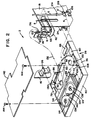
- Figure 1 is a perspective view of interfacing apparatus of the present invention;
- Figure 2 is a partial exploded view of interfacing apparatus of the present invention;
- Figure 3 is an end view of interfacing apparatus of the present invention;
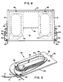
- Figure 4 is a front view of interfacing apparatus of the present invention;
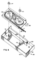
- Figure 5 is a perspective view of a cassette of the present invention;
- Figure 6 is a partial exploded view of a drawer for use with interfacing apparatus of the present invention;
- Figure 7 is an exploded view of a connector panel for use with interfacing apparatus of the present invention; and,
- Figure 8 is a plan view of interfacing apparatus of the present invention.
- The embodiment of this invention which is illustrated in the drawings is particularly suited for achieving the objects of this invention. Figures 1 and 2 depict an
apparatus 2 for interfacing firstoptical fibers 4 of at least one first fiber optical cable 6 such as an external optical cable with second optical fibers 8 (not seen in Figure 1) in the form of, for example, respective internal jumper patch cords. For example, theapparatus 2 is useful in interfacing outside plant cable 6 withinside plant cords 10 connected to telephone transmission equipment, not shown. - The
apparatus 2 includes a housing comprising abase 12 and anopposing top 14. First opposingside wall 16 and secondopposing side wall 18 are also provided extending vertically frombase 12 totop 14. Arear wall 20 depicted in Figures 3 and 4 extends vertically frombase 12 totop 14 and from firstopposing side wall 16 to secondopposing side wall 18. Aforward opening 22 is provided oppositereal wall 20. Means associated with the first and second side walls are provided for slideably supporting a drawer within the housing so that the drawer can be slid relative to the rear wall into the housing and out of the housing at the forward opening. For example,tracks drawer 28. -
Drawer 28 is provided for sliding upon the slideably supporting means such astracks Drawer 28 forms anenclosure 30 including abottom 32, firstopposing side panel 34 and secondopposing side panel 36 each extending vertically frombottom 32, arear panel 38 including two sections extending vertically frombottom 32, and afront panel 40 opposite therear panel 38 and extending vertically frombottom 32 and extending from the firstopposing side wall 34 to the secondopposing side wall 36. - First means are positioned within the housing for storing the second
optical fiber 8. In the preferred embodiment such first means includes a plurality ofremovable cassettes 42. As best seen in Figure 4, the housing includes a first plurality ofopposing guides removable cassettes 42 into and out of the housing. Respectiveopposing guides cassettes 42 to slide upon, respective pairs oftracks top 14, and extending towards therear wall 20, ofapparatus 2. Preferably, the first plurality ofopposing guides opposing wall 16. The housing also preferably includes a second plurality ofopposing guides removable cassettes 42 into and out of the housing. Respectiveopposing guides guides opposing guides additional cassettes 42 to slide upon, respective pairs oftracks top 14, and extending towards therear wall 20, ofapparatus 2. Preferably, the second plurality ofopposing guides opposing wall 18. - Referring to Figure 5, each
respective cassette 42 includesopposing sides opposing guides cassette 42 includes arear edge 56 having a catch-like protuberance 58 extending therefrom. Referring to Figure 4 which depicts somecassettes 42 in place and others removed, it will be observed that arear abutment 58 is provided extending between respectiveopposing guides opposing guides rear abutment 58 includes a first plurality ofapertures 60 each of which is positioned between a respective pair ofopposing guides preferred embodiment apertures 60 are centered betweenrespective guides cassette 42 is guided into the housing by sliding the cassette upon a pair of opposing guides, the catch-like protuberance 58 of such cassette will be received by therespective aperture 60 to lock the cassette in place. A similar second plurality ofapertures 62 is provided each being positioned between a respective pair ofopposing guides cassette 42 which is guided into the housing by sliding upon a pair ofopposing guides - Referring to Figure 5, it will be noted that each
cassette 42 includes ahub 64 havingflanges 66 and includes two pairs of spacedbosses optical fiber 8 to be wound abouthub 64 to take up fiber slack and be held firmly in place bybosses - Second means are provided positioned within the
enclosure 30 for storing the first optical fibers and for storing a plurality of pigtails. For example, in the preferred embodiment such second means includes afirst divider 72 which extends vertically from bottom 32, is parallel torear panel 38, and is positioned midway betweenfront panel 40 andrear panel 38. First opposingside panel 34 and secondopposing side panel 36 include respectiveupper edges flanges base 32 as depicted in Figure 1. In a like manner, the rear panel, which preferably is in the form of twosections 38, and thefirst divider 72, each include respectiveupper edges flanges second divider 90 which extends vertically from bottom 32, is parallel to therear panel 38, and is positioned between therear panel 38 and thefirst divider 72. As depicted in Figures 1 and 2 , preferably the bottom 32 includes afirst aperture 92 positioned in an area adjacent the first opposingside panel 34 and asecond aperture 96 positioned in an area adjacent the second opposingside panel 36. The structure thus far described provides a means for storing the firstoptical fibers 4. - A third means is provided positioned within the
enclosure 30 for splicing an end of respective of the firstoptical fibers 4 to a corresponding first end of respective pigtails which are provided as described herein. For example, in the preferred embodiment such third means includes at least onesplice tray 106. Such splice tray is attached to the bottom 32 of thedrawer 28 in an area between the front panel and thefirst divider 72. In such embodiment the first divider extends from the first opposingside panel 34 towards the second opposingside panel 36, thefirst divider 72 being spaced from the second opposingside panel 36 at 108 to provide an area through whichfibers 4 and the pigtails can extend to thesplice tray 106. Preferably, thesplice tray 106 is attached to thedrawer 28 bybolts 110 which extend vertically from bottom 32 of the drawer throughapertures 112 in thesplice tray 106 which is then held in place by nuts 114. A plurality of similar splice trays can be stacked upon one another when required as depicted in Figure 6. -
Apparatus 2 includes fourth means positioned within the housing for optically connecting an end of respective of the secondoptical fibers 8 to a corresponding second end of respective pigtails provided as described herein. For example, in the preferred embodiment such fourth means includesconnector panels 116 which are positioned between the first plurality of opposingguides guides connector panels 116 being held in place by means ofscrews 118. Each connector panel includes a plurality ofapertures 120 extending therethrough. Means are provided attached to each connector panel for optically connecting secondoptical fibers 8 to respective second ends of respective pigtails as described herein. For example, adapters or attenuators of a type known in the art and generally depicted at 122 are provided into which the secondoptical fiber 8 and the pigtails can be plugged in a known manner. - To render
apparatus 2 operational, and referring to Figures 1 and 2, the outer sheath of cable 6 is stripped therefrom in a known manner to expose the bufferedfibers 4 andstrength member 4′. Subsequently thefibers 4,strength member 4′, and cable 6 are inserted through a clampingmember 124 positioned at second opposingside 18 and clamped firmly in place. Thestrength member 4′ is then secured to a tie-off 126 in a known manner and thefibers 4 are routed through acable entry 128, which extends throughside 18, and onto to thedrawer 28 via theentrance aperture 92, thefibers 4 being secured by tie wraps 130 as desired and the slack being taken up by wrapping thefibers 4 generally circularly in a counter-clockwise direction viewing Figure 2 within the confirms offlanges apparatus 2 can be provided with corresponding hardware and a secondcable entry aperture 128 at the first opposingside 16 to increase the flexibility of the apparatus. Fibers extending from cable fastened atside 16 should be passed throughentrance aperture 96. In other words, preferably the entrance aperture located on the side of the apparatus opposite the cable entry port is the one used to route fibers. - Fiber optical cables known as pigtails serve to bridge first
optical fibers 4 and secondoptical fibers 8. For example, for eachfirst fiber 4 to be connected to a correspondingsecond fiber 8, apigtail 132 is provided. Eachpigtail 132 includes afirst end 134 and asecond end 136. As depicted in Figure 7, eachend 136 is connected to an adapter orattenuator 122 at the rear of theconnector panel 116 in a known manner. Eachpigtail 132 is then routed ontodrawer 28 viaentrance aperture 92, thepigtails 132 being secured by tie wraps 130 as desired and the slack being taken up by wrapping the pigtails generally circularly in a clockwise direction viewing Figure 2 within the confines offlanges fiber 4 andpigtails 132 are then routed as depicted in Figures 2 and 6 through the space provided at 108, wrapped about take-uphubs 138 in amanner allowing fiber 4 andpigtail 132 to be optically coupled at asplice 140 in a known manner. - The inside
optical fibers 8 are in the form of individual jumper patch cords and are coupled to the system as depicted in Figure 2. Referring to Figures 2 and 7, each jumper patch cord includes anend 10 which is connected to the adapter orattenuator 122 at the front of theconnector panel 116 in a known manner. - When all of the connections have been made a
cover 142 is mounted upondrawer 28 byscrews 144 and the drawer is closed. Then thefront cover 146 is closed as depicted in Figure 3 and locked in place. Preferably,front cover 146 is removably hinged to the top of the housing in a known manner at hinges 148 which are positioned adjacent the forward opening of the housing. - Referring to Figure 3, the first opposing
side wall 16 and the second opposingside wall 18 can each include a plurality of optical fiber apertures in the form ofcable entry ports 128. In this manner, access can be provided at the front ofapparatus 2 or at the rear ofapparatus 2 through an aperture in a respective opposing side wall. In a like manner, a fifth means can be provided removably attached to the first and second opposingside walls apertures 128. For example,fiber guards 150 can be attached towalls aperture 128 is being used, by screwing the fiber guard to a mountingangle 152 by means ofscrews 154. - Adjustable mounting
brackets 156 are provided so that by removingscrews 158 thebrackets 156 can be positioned to accommodate various sizes of equipment or to accommodate a wall mounting. - The apparatus of the present invention provides a means by which internal or inside optical fibers can be optically coupled to external or outside optical fibers using equipment which allows for testing and servicing from the front of apparatus which includes a stationary housing and moveable splice tray and cable storage unit. Optical fiber bending is controlled and attenuation is not a problem. The apparatus of the present invention is compact and can be mounted in standard equipment or upon a wall or the like, and yet is readily accessible. Fiber organization is improved so that users can access specific fibers quickly and easily with less risk of breakage and improved productivity.
- The embodiments which have been described herein are but some of several which utilize this invention and are set forth here by way of illustration but not of limitation. It is apparent that many other embodiments which will be readily apparent to those skilled in the art may be made without departing materially from the spirit and scope of this invention.
Claims (15)
- Apparatus for selectively interfacing first optical fibers (4) with second optical fibers (8) comprising:
a housing comprising a base (12) and an opposing top (14), first and second opposing side walls (16,18) extending orthogonally from said base (12) to said top (14), a rear wall extending orthogonally from said base (12) to said top (14) and extending from said first opposing side wall to said second opposing side wall (20), a forward opening (22) opposite said rear wall (18), and means (24,26) associated with said first and second side walls for slidably supporting a drawer (28) within said housing so that said drawer can be slid relative to said rear wall into said housing and out of said housing via said forward opening;
a drawer (28) for sliding upon said slidably supporting means, said drawer forming an enclosure including a bottom (32), first and second opposing side panels (34,36) extending orthogonally from said bottom (32), a rear panel (38) extending orthogonally from said bottom (32), and a front panel (40) opposite said rear panel and extending orthogonally from said bottom (32) and said drawer extending from said first opposing side panel (34) to said second opposing side panel (36);
first means (42,44,46) positioned within said housing for storing said second optical fibers (8);
second means (72,90) positioned within said drawer for storing said first optical fibers (4) and for storing a plurality of pigtails (132);
third means (106) positioned within said enclosure for splicing a first end of each of said first optical fibers (4) to a corresonding first end of a different one of said pigtails (32);
fourth means (116) for optically connecting a second end of each of said second optical fibers (8) to a corresponding second end of a different one of said pigtails (132),
characterized in that
said first means (42) comprises a plurality of slidably removable cassettes and at least a first plurality of opposing pairs of guides (44,46) for slidingly guiding said plurality of removable cassettes (42) into and out of said housing, respective opposing guides (44,46) of said first plurality of opposing guides forming two spaced parallel arrays, each array extending in a direction orthogonal to said top (14), with each guide extending towards said rear wall (20);
said third means comprises at least one splice tray (106) attached to said bottom (32) of said drawer (28) in an area between said front panel and said second means (72) which is also in the drawer; and
wherein said fourth means comprises a connector panel (116) positioned within said housing said connector panel (116) being fixedly positioned adjacent said first means (40,44,46) generally parallel to said rear wall, and generally orthogonal to said top. - The apparatus of claim 1, wherein said first plurality of opposing guides (44,46) are positioned towards a side of said housing adjacent said first opposing wall (16), and a second plurality of opposing guides (48,50) for guiding said plurality of removable cassettes (42) into and out of said housing, respective opposing guides (48,50) of said second plurality of opposing guides (48,50) being stacked orthogonally towards said top (14) and extending towards said rear wall (20), said second plurality of opposing guides (48,50) being positioned towards a side of said housing adjacent said second opposing side wall (18) and the connector panel (116) is positioned between the guides (48,50).
- The apparatus of claim 2, wherein each respective cassette (42) of said plurality of removable cassettes (42) includes opposing sides (52,54) which slide upon respective of said opposing guides (44,46,48,50), and further includes a rear edge (56) having a catch-like protuberance (58) extending therefrom, and further wherein said first means (42,44,46) includes a rear abutment (58) extending between said respective opposing guides (44,46) of said first plurality of opposing guides and between said respective opposing guides (48,50) of said second plurality of opposing guides, said rear abutment (58) including a first plurality of apertures (60), each aperture (60) of said first plurality of apertures (60) being positioned between respective opposing guides (44,46) of said first plurality of opposing guides for receiving a respective catch-like protruberance (58) when a respective cassette (42) of said plurality of removable cassettes is guided by respective opposing guides (44,46) of said first plurality of opposing guides into said housing, and a second plurality of apertures (62), each aperture of said second plurality of apertures (62) being positioned between respective opposing guides (48,50) of said second plurality of opposing guides for receiving a respective catch-like protuberance (58) when a respective cassette (42) of said plurality of removable cassettes is guided by respective opposing guides (48,50) of said second plurality of opposing guides into said housing.
- The apparatus of claim 1 or 3, wherein said second means (72,90) includes a first divider (72) which extends orthogonally from said bottom (32), is parallel to said rear panel (38), and is positioned between said front panel (40) and said rear panel (38), and further wherein said first and second opposing side panels (34,36) include respective upper edges (74,76) spaced from said bottom (32) and having respective first opposing flanges (78,80) extending therefrom, and said rear panel (38) and said first divider (72) include respective upper edges (82,84) spaced from said bottom (32) and having respective second opposing flanges (86,88) extending therefrom.
- The apparatus of claim 4, wherein said second means (72,90) includes a second divider (90) which extends orthogonally from said bottom (32), is parallel to said rear panel (38), and is positioned between said rear panel (38) and said first divider (72), and further wherein said bottom (32) includes a first aperture (92) positioned in an area adjacent said first opposing side panel (34) and a second aperture (96) positioned in an area adjacent said second opposing side panel (36).
- The apparatus of claim 5, wherein said first divider (72) extending from said first opposing side panel (34) towards but being spaced from said second opposing side panel (36).
- The apparatus of claim 2, wherein said one connector panel (116) is positioned between said first plurality of opposing guides (44,46) and said second plurality of opposing guides (48,50).
- The apparatus of claim 7 further including means (122) attached to said connector panel (116) for optically connecting said end of a respective of said second optical fibers (8) to a corresponding second end of a respective pigtail (132).
- The apparatus of claim 1, wherein said drawer (28) includes a cover (142).
- The apparatus of claim 1, wherein said housing includes a front cover (146) removably hinged to said top adjacent said forward opening.
- The apparatus of claim 1, wherein said first and second opposing side walls (16,18) each include a plurality of optical fiber apertures (128).
- The apparatus of claim 11 further including fifth means (150) removably attached to said first and second opposing side walls (16,18) for preventing damage to any optical fibers extending through any of said plurality of optical fiber apertures (128).
- Apparatus for selectively interfacing first optical fibers with second optical fibers (8) in accordance with claim 1,
further
characterized in that
at least one optical fiber aperture (128) extends through at least one of said first and second opposing side walls (16,18), and said second optical fibers extend into said housing through one of said at least one optical fiber aperture. - The apparatus of claim 13, wherein said second means includes a first divider (72) which extends orthogonally from said bottom (32), is parallel to said rear panel (38), and is positioned between said front panel (40) and said rear panel (38), and further wherein said first and second opposing side panels (34,36) include respective upper edges (74,76) spaced from said bottom (32) and having respective first opposing flanges (78,80) extending therefrom, and said rear panel (38) and said first divider (72) include respective upper edges (82,84) spaced from said bottom (32) and having respective second opposing flanges (86,88) extending therefrom.
- The apparatus of claim 14 further including means (122) attached to said connector panel optically connecting a second end of each of said second optical fibers to a corresponding second end of a different one of said pigtails (132).
Applications Claiming Priority (2)
| Application Number | Priority Date | Filing Date | Title |
|---|---|---|---|
| US07/237,477 US4900123A (en) | 1988-08-29 | 1988-08-29 | 1550 nm fiber distribution panel |
| US237477 | 1988-08-29 |
Publications (3)
| Publication Number | Publication Date |
|---|---|
| EP0356942A2 EP0356942A2 (en) | 1990-03-07 |
| EP0356942A3 EP0356942A3 (en) | 1991-03-13 |
| EP0356942B1 true EP0356942B1 (en) | 1995-01-11 |
Family
ID=22893883
Family Applications (1)
| Application Number | Title | Priority Date | Filing Date |
|---|---|---|---|
| EP89115730A Expired - Lifetime EP0356942B1 (en) | 1988-08-29 | 1989-08-25 | 1550NM fiber distribution panel |
Country Status (4)
| Country | Link |
|---|---|
| US (1) | US4900123A (en) |
| EP (1) | EP0356942B1 (en) |
| JP (1) | JPH02111901A (en) |
| DE (1) | DE68920511T2 (en) |
Cited By (9)
| Publication number | Priority date | Publication date | Assignee | Title |
|---|---|---|---|---|
| US9002166B2 (en) | 2011-10-07 | 2015-04-07 | Adc Telecommunications, Inc. | Slidable fiber optic connection module with cable slack management |
| US9057859B2 (en) | 2011-10-07 | 2015-06-16 | Adc Telecommunications, Inc. | Slidable fiber optic connection module with cable slack management |
| US9075203B2 (en) | 2012-01-17 | 2015-07-07 | Adc Telecommunications, Inc. | Fiber optic adapter block |
| US9128262B2 (en) | 2013-02-05 | 2015-09-08 | Adc Telecommunications, Inc. | Slidable telecommunications tray with cable slack management |
| US9170391B2 (en) | 2011-10-07 | 2015-10-27 | Adc Telecommunications, Inc. | Slidable fiber optic connection module with cable slack management |
| US9389384B2 (en) | 2013-02-27 | 2016-07-12 | Commscope Technologies Llc | Slidable fiber optic connection module with cable slack management |
| US9541726B2 (en) | 2013-04-24 | 2017-01-10 | Adc Czech Republic, S.R.O. | Optical fiber distribution system |
| US9568699B2 (en) | 2013-01-29 | 2017-02-14 | CommScope Connectivity Belgium BVBA | Optical fiber distribution system |
| US10025054B2 (en) | 2014-07-10 | 2018-07-17 | Corning Optical Communications LLC | Optical fiber distribution hub with fiber routing structures |
Families Citing this family (180)
| Publication number | Priority date | Publication date | Assignee | Title |
|---|---|---|---|---|
| US3475480A (en) * | 1966-05-17 | 1969-10-28 | Thompson Chem Co Hayward | Synthesis of aromatic nitriles by nitrilizing halogenated intermediates |
| US5071211A (en) * | 1988-12-20 | 1991-12-10 | Northern Telecom Limited | Connector holders and distribution frame and connector holder assemblies for optical cable |
| FR2646928B1 (en) * | 1989-05-11 | 1993-12-24 | Etat Francais Cnet | MODULE AND CONNECTION BOX FOR FIBER OPTIC CABLES |
| US4976510B2 (en) * | 1989-11-20 | 1995-05-09 | Siecor Corp | Communication outlet |
| GB2241591A (en) * | 1990-02-28 | 1991-09-04 | Optical Data Communications Li | Mounting frames for fibre optic or electrical cable organiser trays |
| FR2660077B1 (en) * | 1990-03-20 | 1993-08-20 | Loh Rittal Werk Gmbh Co | CONNECTION BOX FOR FIBER OPTICS. |
| US5092663A (en) * | 1990-05-21 | 1992-03-03 | Gte North Incorporated | Apparatus and method for maintaining slack of fiber optic cable or the like |
| US5208894A (en) * | 1990-07-16 | 1993-05-04 | Adc Telecommunications, Inc. | Fiber optic splice cabinet |
| EP0501336B1 (en) * | 1991-02-27 | 1996-06-05 | Siemens Aktiengesellschaft | Separating housing for lightwave guides |
| US5434944A (en) * | 1991-06-18 | 1995-07-18 | British Telecommunications Public Limited Company | Optical fibre connection equipment |
| US5204929A (en) * | 1991-09-04 | 1993-04-20 | Reliance Comm/Tec Corporation | Fiber patch panel |
| US5247603A (en) * | 1992-01-24 | 1993-09-21 | Minnesota Mining And Manufacturing Company | Fiber optic connection system with exchangeable cross-connect and interconnect cards |
| US5243679A (en) * | 1992-02-07 | 1993-09-07 | Gv Medical, Inc. | Optical fiber advancement, retraction and storage system |
| US5363467A (en) * | 1993-05-28 | 1994-11-08 | Minnesota Mining And Manufacturing Company | Compact fiber optic housing |
| US5446822A (en) * | 1993-05-28 | 1995-08-29 | Minnesota Mining And Manufacturing Company | Connector clip for fiber optic housing |
| CH686267A5 (en) * | 1993-07-30 | 1996-02-15 | G & B Elektro Ag | Stackable cable end termination for optical fibres |
| GB9318633D0 (en) * | 1993-09-08 | 1993-10-27 | Raychem Sa Nv | Organization of optical fibres |
| GB9318654D0 (en) * | 1993-09-08 | 1993-10-27 | Raychem Sa Nv | Optical fibre organizer |
| FR2710419B1 (en) * | 1993-09-24 | 1995-12-15 | Blanchard Anne Marie | Connection device for optical fibers. |
| GB2282457B (en) * | 1993-09-29 | 1996-10-02 | Pirelli General Plc | An assembly for use in connecting optical fibres |
| US5367598A (en) * | 1993-10-21 | 1994-11-22 | Nec America, Inc. | Interface chassis for fiber optic transport system |
| US5490229A (en) * | 1993-12-08 | 1996-02-06 | At&T Ipm Corp. | Slidably mounted optical fiber distribution tray |
| US5402515A (en) * | 1994-03-01 | 1995-03-28 | Minnesota Mining And Manufacturing Company | Fiber distribution frame system, cabinets, trays and fiber optic connector couplings |
| US5511144A (en) * | 1994-06-13 | 1996-04-23 | Siecor Corporation | Optical distribution frame |
| GB2312969B (en) * | 1994-06-20 | 1998-04-01 | Pirelli General Plc | Apparatus including releasably connected guide tubes for use in interconnecting optical fibres |
| US5408570A (en) * | 1994-06-30 | 1995-04-18 | Minnesota Mining And Manufacturing Company | Fiber optic housing with low part count |
| US5459808A (en) * | 1994-06-30 | 1995-10-17 | Minnesota Mining And Manufacturing Company | Fiber optic housing with removable chassis and method using same |
| US5481639A (en) * | 1994-10-28 | 1996-01-02 | At&T Corp. | Compact closure for optical fiber cable |
| JP2931219B2 (en) * | 1994-11-15 | 1999-08-09 | 日本電信電話株式会社 | Module for terminating optical fiber cable |
| GB2298496B (en) * | 1995-02-28 | 1998-06-03 | Bowthorpe Plc | Optical fibre splice storage arrangements |
| FR2733843B1 (en) * | 1995-05-03 | 1997-05-30 | Alcatel Submarcom | ORGANIZER DEVICE FOR CONNECTING FIBER OPTIC CABLES AND JUNCTION BOX FOR OPTICAL CABLES |
| US5613030A (en) * | 1995-05-15 | 1997-03-18 | The Whitaker Corporation | High density fiber optic interconnection enclosure |
| US5724469A (en) * | 1996-01-26 | 1998-03-03 | Ortronics, Inc. | Adjustable fiber storage plate |
| US5825962A (en) * | 1996-12-31 | 1998-10-20 | Siecor Corporation | Optical fiber splice housing |
| EP0859257B1 (en) * | 1997-02-14 | 2006-09-20 | Nexans Deutschland Industries AG % Co KG. | Device for branching a telecommunications cable comprised of a plurality of strands containing optical fibres |
| US5975769A (en) * | 1997-07-08 | 1999-11-02 | Telect, Inc. | Universal fiber optic module system |
| US5946440A (en) * | 1997-11-17 | 1999-08-31 | Adc Telecommunications, Inc. | Optical fiber cable management device |
| US6215937B1 (en) | 1998-09-24 | 2001-04-10 | Thomas & Betts International, Inc. | Adjustable fiber optic strand storage unit |
| US6201919B1 (en) | 1998-12-16 | 2001-03-13 | Adc Telecommunications, Inc | Fiber distribution frame |
| US6760531B1 (en) | 1999-03-01 | 2004-07-06 | Adc Telecommunications, Inc. | Optical fiber distribution frame with outside plant enclosure |
| SE517302C2 (en) * | 1999-05-27 | 2002-05-21 | Ericsson Telefon Ab L M | Apparatus for delimiting and separating optical fibers in an isolated space |
| US6438310B1 (en) | 2000-01-24 | 2002-08-20 | Adc Telecommunications, Inc. | Cable management panel with sliding drawer |
| US6504988B1 (en) * | 2000-01-24 | 2003-01-07 | Adc Telecommunications, Inc. | Cable management panel with sliding drawer |
| CN1398232A (en) * | 2000-02-07 | 2003-02-19 | 特赫鲁赫鲁器材有限公司 | Portable-pente ski tow |
| US6418262B1 (en) * | 2000-03-13 | 2002-07-09 | Adc Telecommunications, Inc. | Fiber distribution frame with fiber termination blocks |
| US6694084B1 (en) * | 2000-06-23 | 2004-02-17 | Mitsubishi Denki Kabushiki Kaisha | Optical cable excess handling unit and optical cable wiring method |
| US6845207B2 (en) * | 2001-02-12 | 2005-01-18 | Fiber Optic Network Solutions Corp. | Optical fiber enclosure system |
| JP4524436B2 (en) * | 2001-04-25 | 2010-08-18 | ネッツエスアイ東洋株式会社 | Extra length optical cable processing structure |
| US6944387B2 (en) | 2001-04-30 | 2005-09-13 | Telect, Inc. | Fiber optic connector tray system |
| US6674952B2 (en) | 2001-04-30 | 2004-01-06 | Telect, Inc. | Fiber optic cable bend radius protection system |
| US6819857B2 (en) | 2001-10-12 | 2004-11-16 | Adc Telecommunications, Inc. | Rotating vertical fiber tray and methods |
| US6621975B2 (en) * | 2001-11-30 | 2003-09-16 | Corning Cable Systems Llc | Distribution terminal for network access point |
| US6515227B1 (en) | 2002-05-24 | 2003-02-04 | Alcoa Fujikura Limited | Fiber optic cable management enclosure with integral bend radius control |
| US6925241B2 (en) * | 2002-10-11 | 2005-08-02 | 3M Innovative Properties Company | Drawer for the management of optical fibers |
| JP4390705B2 (en) * | 2002-10-11 | 2009-12-24 | スリーエム イノベイティブ プロパティズ カンパニー | An array of optical fiber splicing cassettes |
| US7142764B2 (en) | 2003-03-20 | 2006-11-28 | Tyco Electronics Corporation | Optical fiber interconnect cabinets, termination modules and fiber connectivity management for the same |
| US7198409B2 (en) | 2003-06-30 | 2007-04-03 | Adc Telecommunications, Inc. | Fiber optic connector holder and method |
| US7233731B2 (en) * | 2003-07-02 | 2007-06-19 | Adc Telecommunications, Inc. | Telecommunications connection cabinet |
| US7369741B2 (en) | 2003-11-17 | 2008-05-06 | Fiber Optics Network Solutions Corp. | Storage adapter with dust cap posts |
| US6983095B2 (en) | 2003-11-17 | 2006-01-03 | Fiber Optic Network Solutions Corporation | Systems and methods for managing optical fibers and components within an enclosure in an optical communications network |
| US7200316B2 (en) * | 2003-11-26 | 2007-04-03 | Corning Cable Systems Llc | Connector housing for a communication network |
| US6944389B2 (en) * | 2003-11-26 | 2005-09-13 | Corning Cable Systems Llc | Connector housing having a sliding tray with a hingeable portion |
| US7013074B2 (en) * | 2004-02-06 | 2006-03-14 | Corning Cable Systems Llc | Optical connection closure having at least one connector port |
| US20050207711A1 (en) * | 2004-03-19 | 2005-09-22 | Vo Chanh C | Optical termination pedestal |
| US7218827B2 (en) | 2004-06-18 | 2007-05-15 | Adc Telecommunications, Inc. | Multi-position fiber optic connector holder and method |
| DE102004033229A1 (en) * | 2004-07-08 | 2006-01-26 | Ewe Ag | Device for linking at least one branch optical waveguide to a main optical waveguide |
| WO2006012389A1 (en) * | 2004-07-22 | 2006-02-02 | Panduit Corp. | Front access punch down patch panel |
| JP4328713B2 (en) * | 2004-11-30 | 2009-09-09 | 株式会社アドバンテスト | Test apparatus, optical connection unit, and manufacturing method |
| US20060215980A1 (en) * | 2005-03-24 | 2006-09-28 | Yilmaz Bayazit | Splice tray arrangement |
| US7194181B2 (en) | 2005-03-31 | 2007-03-20 | Adc Telecommunications, Inc. | Adapter block including connector storage |
| US7272291B2 (en) * | 2005-08-25 | 2007-09-18 | Adc Telecommunications, Inc. | Splice chip device |
| US7310471B2 (en) * | 2005-08-25 | 2007-12-18 | Adc Telecommunications, Inc. | Stackable splice chip device |
| US7623749B2 (en) * | 2005-08-30 | 2009-11-24 | Adc Telecommunications, Inc. | Fiber distribution hub with modular termination blocks |
| US7274852B1 (en) * | 2005-12-02 | 2007-09-25 | Adc Telecommunications, Inc. | Splice tray arrangement |
| US7816602B2 (en) | 2006-02-13 | 2010-10-19 | Adc Telecommunications, Inc. | Fiber distribution hub with outside accessible grounding terminals |
| US7720343B2 (en) | 2006-02-13 | 2010-05-18 | Adc Telecommunications, Inc. | Fiber distribution hub with swing frame and modular termination panels |
| US7760984B2 (en) | 2006-05-04 | 2010-07-20 | Adc Telecommunications, Inc. | Fiber distribution hub with swing frame and wrap-around doors |
| US7509015B2 (en) * | 2006-07-26 | 2009-03-24 | Ortronics, Inc. | Secure fiber optic network cassette assembly |
| US7349615B2 (en) * | 2006-08-25 | 2008-03-25 | Corning Cable Systems Llc | Fiber optic housing assembly for fiber optic connections comprising pivotable portion |
| CN101195453A (en) * | 2006-12-05 | 2008-06-11 | 3M创新有限公司 | Cable slack process equipment |
| US7496268B2 (en) * | 2006-12-13 | 2009-02-24 | Corning Cable Systems Llc | High density fiber optic hardware |
| US7822310B2 (en) * | 2007-02-28 | 2010-10-26 | Corning Cable Systems Llc | Fiber optic splice trays |
| US7620287B2 (en) * | 2007-05-31 | 2009-11-17 | Corning Cable Systems Llc | Telecommunications housing with optical fiber management |
| US8798427B2 (en) * | 2007-09-05 | 2014-08-05 | Corning Cable Systems Llc | Fiber optic terminal assembly |
| US8229265B2 (en) * | 2007-11-21 | 2012-07-24 | Adc Telecommunications, Inc. | Fiber distribution hub with multiple configurations |
| US20090211171A1 (en) * | 2008-02-25 | 2009-08-27 | Timothy Frederick Summers | Multi-dwelling unit multipurpose signal distribution apparatus |
| US7889961B2 (en) | 2008-03-27 | 2011-02-15 | Corning Cable Systems Llc | Compact, high-density adapter module, housing assembly and frame assembly for optical fiber telecommunications |
| CN101583256A (en) * | 2008-05-12 | 2009-11-18 | 爱德龙通讯系统(上海)有限公司 | Cable management panel |
| ES2560802T3 (en) | 2008-08-27 | 2016-02-22 | Adc Telecommunications, Inc. | Fiber optic adapter with integrally molded bushing alignment structure |
| US8452148B2 (en) | 2008-08-29 | 2013-05-28 | Corning Cable Systems Llc | Independently translatable modules and fiber optic equipment trays in fiber optic equipment |
| US11294135B2 (en) | 2008-08-29 | 2022-04-05 | Corning Optical Communications LLC | High density and bandwidth fiber optic apparatuses and related equipment and methods |
| CN102209921B (en) * | 2008-10-09 | 2015-11-25 | 康宁光缆系统有限公司 | There is the fibre-optic terminus supported from the adapter panel of the input and output optical fiber of optical splitters |
| US8879882B2 (en) * | 2008-10-27 | 2014-11-04 | Corning Cable Systems Llc | Variably configurable and modular local convergence point |
| MX2011005380A (en) | 2008-11-21 | 2011-06-06 | Adc Telecommunications Inc | Fiber optic telecommunications module. |
| ATE534049T1 (en) * | 2009-02-24 | 2011-12-15 | Ccs Technology Inc | CABLE HOLDING DEVICE OR ARRANGEMENT FOR USE WITH A CABLE |
| US20100220967A1 (en) * | 2009-02-27 | 2010-09-02 | Cooke Terry L | Hinged Fiber Optic Module Housing and Module |
| EP2237091A1 (en) * | 2009-03-31 | 2010-10-06 | Corning Cable Systems LLC | Removably mountable fiber optic terminal |
| US8699838B2 (en) | 2009-05-14 | 2014-04-15 | Ccs Technology, Inc. | Fiber optic furcation module |
| US8280216B2 (en) | 2009-05-21 | 2012-10-02 | Corning Cable Systems Llc | Fiber optic equipment supporting moveable fiber optic equipment tray(s) and module(s), and related equipment and methods |
| US9075216B2 (en) | 2009-05-21 | 2015-07-07 | Corning Cable Systems Llc | Fiber optic housings configured to accommodate fiber optic modules/cassettes and fiber optic panels, and related components and methods |
| US8712206B2 (en) * | 2009-06-19 | 2014-04-29 | Corning Cable Systems Llc | High-density fiber optic modules and module housings and related equipment |
| US8433171B2 (en) * | 2009-06-19 | 2013-04-30 | Corning Cable Systems Llc | High fiber optic cable packing density apparatus |
| AU2010263057A1 (en) | 2009-06-19 | 2012-02-02 | Corning Cable Systems Llc | High density and bandwidth fiber optic apparatuses and related equipment and methods |
| CA2765790A1 (en) * | 2009-06-19 | 2010-12-23 | Corning Cable Systems Llc | High capacity fiber optic connection infrastructure apparatus |
| AU2010270959A1 (en) * | 2009-06-22 | 2012-02-02 | Corning Cable Systems Llc | Fiber optic cable parking device |
| US20110030832A1 (en) * | 2009-08-06 | 2011-02-10 | 3M Innovative Properties Company | Adhesive backed ducts for cabling applications |
| US8467651B2 (en) | 2009-09-30 | 2013-06-18 | Ccs Technology Inc. | Fiber optic terminals configured to dispose a fiber optic connection panel(s) within an optical fiber perimeter and related methods |
| US20110129186A1 (en) * | 2009-11-30 | 2011-06-02 | Lewallen C Paul | Fiber Optic Module Assembly and Associated Methods |
| US8208781B1 (en) * | 2009-12-03 | 2012-06-26 | Adtran, Inc. | Fiber optic connector panel |
| US8625950B2 (en) * | 2009-12-18 | 2014-01-07 | Corning Cable Systems Llc | Rotary locking apparatus for fiber optic equipment trays and related methods |
| US8593828B2 (en) | 2010-02-04 | 2013-11-26 | Corning Cable Systems Llc | Communications equipment housings, assemblies, and related alignment features and methods |
| EP2542930A1 (en) | 2010-03-02 | 2013-01-09 | Tyco Electronics Services GmbH | Fibre-optic telecommunication module |
| US9547144B2 (en) | 2010-03-16 | 2017-01-17 | Corning Optical Communications LLC | Fiber optic distribution network for multiple dwelling units |
| US8913866B2 (en) * | 2010-03-26 | 2014-12-16 | Corning Cable Systems Llc | Movable adapter panel |
| US8792767B2 (en) | 2010-04-16 | 2014-07-29 | Ccs Technology, Inc. | Distribution device |
| AU2011265751B2 (en) | 2010-04-16 | 2015-09-10 | Corning Optical Communications LLC | Sealing and strain relief device for data cables |
| EP2381284B1 (en) | 2010-04-23 | 2014-12-31 | CCS Technology Inc. | Under floor fiber optic distribution device |
| US8705926B2 (en) | 2010-04-30 | 2014-04-22 | Corning Optical Communications LLC | Fiber optic housings having a removable top, and related components and methods |
| US8660397B2 (en) | 2010-04-30 | 2014-02-25 | Corning Cable Systems Llc | Multi-layer module |
| US9519118B2 (en) | 2010-04-30 | 2016-12-13 | Corning Optical Communications LLC | Removable fiber management sections for fiber optic housings, and related components and methods |
| US9632270B2 (en) | 2010-04-30 | 2017-04-25 | Corning Optical Communications LLC | Fiber optic housings configured for tool-less assembly, and related components and methods |
| US9720195B2 (en) | 2010-04-30 | 2017-08-01 | Corning Optical Communications LLC | Apparatuses and related components and methods for attachment and release of fiber optic housings to and from an equipment rack |
| US9075217B2 (en) | 2010-04-30 | 2015-07-07 | Corning Cable Systems Llc | Apparatuses and related components and methods for expanding capacity of fiber optic housings |
| US8879881B2 (en) | 2010-04-30 | 2014-11-04 | Corning Cable Systems Llc | Rotatable routing guide and assembly |
| US8718436B2 (en) | 2010-08-30 | 2014-05-06 | Corning Cable Systems Llc | Methods, apparatuses for providing secure fiber optic connections |
| US9547145B2 (en) | 2010-10-19 | 2017-01-17 | Corning Optical Communications LLC | Local convergence point for multiple dwelling unit fiber optic distribution network |
| US9279951B2 (en) | 2010-10-27 | 2016-03-08 | Corning Cable Systems Llc | Fiber optic module for limited space applications having a partially sealed module sub-assembly |
| US8662760B2 (en) | 2010-10-29 | 2014-03-04 | Corning Cable Systems Llc | Fiber optic connector employing optical fiber guide member |
| US9116324B2 (en) | 2010-10-29 | 2015-08-25 | Corning Cable Systems Llc | Stacked fiber optic modules and fiber optic equipment configured to support stacked fiber optic modules |
| CA2819235C (en) | 2010-11-30 | 2018-01-16 | Corning Cable Systems Llc | Fiber device holder and strain relief device |
| EP2671107A1 (en) | 2011-02-02 | 2013-12-11 | Corning Cable Systems LLC | Dense shuttered fiber optic connectors and assemblies suitable for establishing optical connections for optical backplanes in equipment racks |
| US9008485B2 (en) | 2011-05-09 | 2015-04-14 | Corning Cable Systems Llc | Attachment mechanisms employed to attach a rear housing section to a fiber optic housing, and related assemblies and methods |
| CN103649805B (en) | 2011-06-30 | 2017-03-15 | 康宁光电通信有限责任公司 | Fiber plant assembly of shell using non-U-width size and associated method |
| US8953924B2 (en) | 2011-09-02 | 2015-02-10 | Corning Cable Systems Llc | Removable strain relief brackets for securing fiber optic cables and/or optical fibers to fiber optic equipment, and related assemblies and methods |
| US9417418B2 (en) | 2011-09-12 | 2016-08-16 | Commscope Technologies Llc | Flexible lensed optical interconnect device for signal distribution |
| EP2764390B1 (en) | 2011-10-07 | 2020-12-02 | CommScope Technologies LLC | Fiber optic cassette, system, and method |
| US9038832B2 (en) | 2011-11-30 | 2015-05-26 | Corning Cable Systems Llc | Adapter panel support assembly |
| US9219546B2 (en) | 2011-12-12 | 2015-12-22 | Corning Optical Communications LLC | Extremely high frequency (EHF) distributed antenna systems, and related components and methods |
| US10110307B2 (en) | 2012-03-02 | 2018-10-23 | Corning Optical Communications LLC | Optical network units (ONUs) for high bandwidth connectivity, and related components and methods |
| US9004778B2 (en) | 2012-06-29 | 2015-04-14 | Corning Cable Systems Llc | Indexable optical fiber connectors and optical fiber connector arrays |
| US9250409B2 (en) | 2012-07-02 | 2016-02-02 | Corning Cable Systems Llc | Fiber-optic-module trays and drawers for fiber-optic equipment |
| US9049500B2 (en) | 2012-08-31 | 2015-06-02 | Corning Cable Systems Llc | Fiber optic terminals, systems, and methods for network service management |
| US9042702B2 (en) | 2012-09-18 | 2015-05-26 | Corning Cable Systems Llc | Platforms and systems for fiber optic cable attachment |
| US9146362B2 (en) | 2012-09-21 | 2015-09-29 | Adc Telecommunications, Inc. | Insertion and removal tool for a fiber optic ferrule alignment sleeve |
| US9195021B2 (en) * | 2012-09-21 | 2015-11-24 | Adc Telecommunications, Inc. | Slidable fiber optic connection module with cable slack management |
| US10082636B2 (en) | 2012-09-21 | 2018-09-25 | Commscope Technologies Llc | Slidable fiber optic connection module with cable slack management |
| ES2792122T3 (en) | 2012-09-28 | 2020-11-10 | Commscope Connectivity Uk Ltd | Fiber optic cassette |
| US9146374B2 (en) | 2012-09-28 | 2015-09-29 | Adc Telecommunications, Inc. | Rapid deployment packaging for optical fiber |
| US9223094B2 (en) | 2012-10-05 | 2015-12-29 | Tyco Electronics Nederland Bv | Flexible optical circuit, cassettes, and methods |
| US8909019B2 (en) * | 2012-10-11 | 2014-12-09 | Ccs Technology, Inc. | System comprising a plurality of distribution devices and distribution device |
| EP2725397B1 (en) | 2012-10-26 | 2015-07-29 | CCS Technology, Inc. | Fiber optic management unit and fiber optic distribution device |
| US8985862B2 (en) | 2013-02-28 | 2015-03-24 | Corning Cable Systems Llc | High-density multi-fiber adapter housings |
| US9435975B2 (en) | 2013-03-15 | 2016-09-06 | Commscope Technologies Llc | Modular high density telecommunications frame and chassis system |
| EP2989496B1 (en) | 2013-04-24 | 2019-06-12 | CommScope Connectivity Belgium BVBA | Universal mounting mechanism for mounting a telecommunications chassis to a telecommunications fixture |
| CN106133572B (en) | 2014-01-28 | 2018-11-09 | Adc电信公司 | Slidably optical link module with cable slack management |
| US9494758B2 (en) | 2014-04-03 | 2016-11-15 | Commscope Technologies Llc | Fiber optic distribution system |
| WO2016094331A1 (en) | 2014-12-10 | 2016-06-16 | Commscope Technologies Llc | Fiber optic cable slack management module |
| US10261281B2 (en) | 2015-04-03 | 2019-04-16 | CommScope Connectivity Belgium BVBA | Telecommunications distribution elements |
| WO2016168337A1 (en) * | 2015-04-13 | 2016-10-20 | Commscope Technologies Llc | Telecommunications chassis and module |
| EP3296785A4 (en) | 2015-05-15 | 2019-05-29 | ADC Telecommunications (Shanghai) Distribution Co., Ltd. | Alignment sleeve assembly and optical fibre adapter |
| WO2017184508A1 (en) | 2016-04-19 | 2017-10-26 | Commscope, Inc. Of North Carolina | Telecommunications chassis with slidable trays |
| WO2017184501A1 (en) | 2016-04-19 | 2017-10-26 | Commscope, Inc. Of North Carolina | Door assembly for a telecommunications chassis with a combination hinge structure |
| CN109196401A (en) * | 2016-05-18 | 2019-01-11 | 康普连通比利时私人有限公司 | Cable slack portion stores equipment |
| CN106324777B (en) * | 2016-11-01 | 2019-03-22 | 南京普天天纪楼宇智能有限公司 | A kind of high-density optical-fiber junction box |
| EP3586180B1 (en) * | 2017-02-23 | 2022-09-14 | Commscope Technologies LLC | High fiber count termination device |
| US11215767B2 (en) | 2017-06-07 | 2022-01-04 | Commscope Technologies Llc | Fiber optic adapter and cassette |
| WO2019070682A2 (en) | 2017-10-02 | 2019-04-11 | Commscope Technologies Llc | Fiber optic circuit and preparation method |
| WO2019079419A1 (en) | 2017-10-18 | 2019-04-25 | Commscope Technologies Llc | Fiber optic connection cassette |
| US11852882B2 (en) | 2018-02-28 | 2023-12-26 | Commscope Technologies Llc | Packaging assembly for telecommunications equipment |
| WO2019204317A1 (en) | 2018-04-16 | 2019-10-24 | Commscope Technologies Llc | Adapter structure |
| WO2019201878A1 (en) | 2018-04-17 | 2019-10-24 | CommScope Connectivity Belgium BVBA | Telecommunications distribution elements |
| DK3844972T3 (en) | 2018-08-31 | 2022-10-17 | CommScope Connectivity Belgium BVBA | FRAME ASSEMBLIES FOR OPTICAL FIBER DISTRIBUTION ELEMENTS |
| EP3844973A1 (en) | 2018-08-31 | 2021-07-07 | CommScope Connectivity Belgium BVBA | Frame assemblies for optical fiber distribution elements |
| WO2020043911A1 (en) | 2018-08-31 | 2020-03-05 | CommScope Connectivity Belgium BVBA | Frame assemblies for optical fiber distribution elements |
| WO2020043909A1 (en) | 2018-08-31 | 2020-03-05 | CommScope Connectivity Belgium BVBA | Frame assemblies for optical fiber distribution elements |
| EP3914947A1 (en) | 2019-01-25 | 2021-12-01 | CommScope Connectivity Belgium BVBA | Frame assemblies for optical fiber distribution elements |
| US11237348B2 (en) * | 2019-04-17 | 2022-02-01 | Afl Ig Llc | Patch panel with lifting cassette removal |
| US11575228B2 (en) | 2020-07-27 | 2023-02-07 | Raytheon Company | Helical strain relief for electrical conductors, fiber optic cables, or other cables |
| US20230141550A1 (en) * | 2021-11-10 | 2023-05-11 | Opterna Am, Inc. | Rack mountable panel for optimizing slack storage and management of optical fiber cables |
| WO2024072990A1 (en) * | 2022-09-29 | 2024-04-04 | viaPhoton, Inc. | Miniature network interface device |
Family Cites Families (12)
| Publication number | Priority date | Publication date | Assignee | Title |
|---|---|---|---|---|
| US4266853A (en) * | 1979-03-12 | 1981-05-12 | Northern Telecom Limited | Device for organizing optical fibers and the like |
| FR2538918A1 (en) * | 1983-01-05 | 1984-07-06 | Telecommunications Sa | FIBER OPTIC CONNECTION AND BREWING BOX |
| US4595255A (en) * | 1983-08-24 | 1986-06-17 | Fiberlan, Inc. | Optical fiber wiring center |
| US4702551A (en) * | 1984-10-11 | 1987-10-27 | Reliance Comm/Tec Corporation | Method and apparatus for handling and storing cabled spliced ends of fiber optics |
| CA1249741A (en) * | 1984-10-25 | 1989-02-07 | Michael J. Donaldson | Optical cable terminating equipment |
| FR2575558B1 (en) * | 1984-12-28 | 1987-01-30 | Cables De Lyon Geoffroy Delore | DEVICE FOR CONNECTING AN OPTICAL FIBER CABLE TO A JUNCTION BOX |
| GB8514389D0 (en) * | 1985-06-07 | 1985-07-10 | Telephone Cables Ltd | Joint closure housing |
| DE3528246A1 (en) * | 1985-08-07 | 1987-02-12 | Standard Elektrik Lorenz Ag | Rack for telecommunications technology |
| EP0215668B1 (en) * | 1985-09-17 | 1990-12-19 | Adc Telecommunications, Inc. | Optical fiber distribution apparatus |
| US4679896A (en) * | 1985-09-27 | 1987-07-14 | Preformed Line Products Company | Optical fiber splice organizer |
| DE3537889A1 (en) * | 1985-10-24 | 1987-04-30 | Sedlbauer Wilhelm Gmbh | Distributor rack for fibre-optic cables |
| US4793682A (en) * | 1988-01-11 | 1988-12-27 | Gte Products Corporation | Fiber optic splice and fiber holder and housing therefor |
-
1988
- 1988-08-29 US US07/237,477 patent/US4900123A/en not_active Expired - Lifetime
-
1989
- 1989-08-25 EP EP89115730A patent/EP0356942B1/en not_active Expired - Lifetime
- 1989-08-25 DE DE68920511T patent/DE68920511T2/en not_active Expired - Fee Related
- 1989-08-25 JP JP1217645A patent/JPH02111901A/en active Pending
Cited By (15)
| Publication number | Priority date | Publication date | Assignee | Title |
|---|---|---|---|---|
| US9354416B2 (en) | 2011-10-07 | 2016-05-31 | Commscope Technologies Llc | Slidable fiber optic connection module with cable slack management |
| US9057859B2 (en) | 2011-10-07 | 2015-06-16 | Adc Telecommunications, Inc. | Slidable fiber optic connection module with cable slack management |
| US9069150B2 (en) | 2011-10-07 | 2015-06-30 | Adc Telecommunications, Inc. | Slidable fiber optic connection module with cable slack management |
| US9002166B2 (en) | 2011-10-07 | 2015-04-07 | Adc Telecommunications, Inc. | Slidable fiber optic connection module with cable slack management |
| US9541725B2 (en) | 2011-10-07 | 2017-01-10 | Commscope Technologies Llc | Slidable fiber optic connection module with cable slack management |
| US9170391B2 (en) | 2011-10-07 | 2015-10-27 | Adc Telecommunications, Inc. | Slidable fiber optic connection module with cable slack management |
| US9329353B2 (en) | 2011-10-07 | 2016-05-03 | Commscope Technologies Llc | Slidable fiber optic connection module with cable slack management |
| US9075203B2 (en) | 2012-01-17 | 2015-07-07 | Adc Telecommunications, Inc. | Fiber optic adapter block |
| US9429714B2 (en) | 2012-01-17 | 2016-08-30 | Commscope Technologies Llc | Fiber optic adapter block |
| US9568699B2 (en) | 2013-01-29 | 2017-02-14 | CommScope Connectivity Belgium BVBA | Optical fiber distribution system |
| US9523833B2 (en) | 2013-02-05 | 2016-12-20 | Commscope Technologies Llc | Slidable telecommunications tray with cable slack management |
| US9128262B2 (en) | 2013-02-05 | 2015-09-08 | Adc Telecommunications, Inc. | Slidable telecommunications tray with cable slack management |
| US9389384B2 (en) | 2013-02-27 | 2016-07-12 | Commscope Technologies Llc | Slidable fiber optic connection module with cable slack management |
| US9541726B2 (en) | 2013-04-24 | 2017-01-10 | Adc Czech Republic, S.R.O. | Optical fiber distribution system |
| US10025054B2 (en) | 2014-07-10 | 2018-07-17 | Corning Optical Communications LLC | Optical fiber distribution hub with fiber routing structures |
Also Published As
| Publication number | Publication date |
|---|---|
| JPH02111901A (en) | 1990-04-24 |
| EP0356942A2 (en) | 1990-03-07 |
| DE68920511T2 (en) | 1995-05-04 |
| US4900123A (en) | 1990-02-13 |
| EP0356942A3 (en) | 1991-03-13 |
| DE68920511D1 (en) | 1995-02-23 |
Similar Documents
| Publication | Publication Date | Title |
|---|---|---|
| EP0356942B1 (en) | 1550NM fiber distribution panel | |
| US4898448A (en) | Fiber distribution panel | |
| US11579395B2 (en) | Optical fiber distribution system | |
| US10509190B2 (en) | Multi-positionable telecommunications tray | |
| US9810868B2 (en) | Optical fiber distribution frame with outside plant enclosure | |
| EP0657757B1 (en) | Optical fiber distribution apparatus | |
| US7574093B2 (en) | Outside plant enclosure with pivoting fiber trays | |
| EP0717863B1 (en) | Optical fibre organizer | |
| US5247603A (en) | Fiber optic connection system with exchangeable cross-connect and interconnect cards | |
| EP1621907B1 (en) | Distribution frame for an optical communication network | |
| US6327414B1 (en) | Apparatus and method for interconnecting fiber cables | |
| US7751672B2 (en) | Low profile fiber distribution hub | |
| EP2255234B1 (en) | Optical fibre organiser | |
| US5208894A (en) | Fiber optic splice cabinet | |
| US20110052133A1 (en) | Fiber organizer tray and telecommunications enclosure | |
| US20190072736A1 (en) | High density distribution frame with an integrated splicing compartment | |
| JP2007516453A (en) | Optical fiber cable distribution frame | |
| EP3230780B1 (en) | Fiber optic cable slack management module | |
| EP0466668A2 (en) | Fiber optic connector module | |
| WO2021156389A1 (en) | Telecommunications module arrangements | |
| WO1999047960A1 (en) | Optical fibre overlength storage | |
| US20230072251A1 (en) | Telecommunications enclosure | |
| GB2351359A (en) | Optical fibre connection and storage unit | |
| WO2023212339A1 (en) | Telecommunications cabinet |
Legal Events
| Date | Code | Title | Description |
|---|---|---|---|
| PUAI | Public reference made under article 153(3) epc to a published international application that has entered the european phase |
Free format text: ORIGINAL CODE: 0009012 |
|
| 17P | Request for examination filed |
Effective date: 19890825 |
|
| AK | Designated contracting states |
Kind code of ref document: A2 Designated state(s): DE FR GB NL |
|
| PUAL | Search report despatched |
Free format text: ORIGINAL CODE: 0009013 |
|
| AK | Designated contracting states |
Kind code of ref document: A3 Designated state(s): DE FR GB NL |
|
| RAP1 | Party data changed (applicant data changed or rights of an application transferred) |
Owner name: GTE CONTROL DEVICES INCORPORATED |
|
| 17Q | First examination report despatched |
Effective date: 19921008 |
|
| RAP1 | Party data changed (applicant data changed or rights of an application transferred) |
Owner name: GTE CONTROL DEVICES OF PUERTO RICO INCORPORATED |
|
| GRAA | (expected) grant |
Free format text: ORIGINAL CODE: 0009210 |
|
| AK | Designated contracting states |
Kind code of ref document: B1 Designated state(s): DE FR GB NL |
|
| PG25 | Lapsed in a contracting state [announced via postgrant information from national office to epo] |
Ref country code: NL Effective date: 19950111 |
|
| ET | Fr: translation filed | ||
| REF | Corresponds to: |
Ref document number: 68920511 Country of ref document: DE Date of ref document: 19950223 |
|
| NLV1 | Nl: lapsed or annulled due to failure to fulfill the requirements of art. 29p and 29m of the patents act | ||
| PGFP | Annual fee paid to national office [announced via postgrant information from national office to epo] |
Ref country code: FR Payment date: 19950717 Year of fee payment: 7 |
|
| PGFP | Annual fee paid to national office [announced via postgrant information from national office to epo] |
Ref country code: DE Payment date: 19950725 Year of fee payment: 7 |
|
| PGFP | Annual fee paid to national office [announced via postgrant information from national office to epo] |
Ref country code: GB Payment date: 19950727 Year of fee payment: 7 |
|
| PLBE | No opposition filed within time limit |
Free format text: ORIGINAL CODE: 0009261 |
|
| STAA | Information on the status of an ep patent application or granted ep patent |
Free format text: STATUS: NO OPPOSITION FILED WITHIN TIME LIMIT |
|
| 26N | No opposition filed | ||
| PG25 | Lapsed in a contracting state [announced via postgrant information from national office to epo] |
Ref country code: GB Effective date: 19960825 |
|
| GBPC | Gb: european patent ceased through non-payment of renewal fee |
Effective date: 19960825 |
|
| PG25 | Lapsed in a contracting state [announced via postgrant information from national office to epo] |
Ref country code: FR Effective date: 19970430 |
|
| PG25 | Lapsed in a contracting state [announced via postgrant information from national office to epo] |
Ref country code: DE Effective date: 19970501 |
|
| REG | Reference to a national code |
Ref country code: FR Ref legal event code: ST |