EP0356628A2 - Device for covering expansion and settlement joints - Google Patents
Device for covering expansion and settlement joints Download PDFInfo
- Publication number
- EP0356628A2 EP0356628A2 EP89110079A EP89110079A EP0356628A2 EP 0356628 A2 EP0356628 A2 EP 0356628A2 EP 89110079 A EP89110079 A EP 89110079A EP 89110079 A EP89110079 A EP 89110079A EP 0356628 A2 EP0356628 A2 EP 0356628A2
- Authority
- EP
- European Patent Office
- Prior art keywords
- groove
- building floor
- anchoring
- bridging
- leg
- Prior art date
- Legal status (The legal status is an assumption and is not a legal conclusion. Google has not performed a legal analysis and makes no representation as to the accuracy of the status listed.)
- Granted
Links
Images
Classifications
-
- E—FIXED CONSTRUCTIONS
- E01—CONSTRUCTION OF ROADS, RAILWAYS, OR BRIDGES
- E01D—CONSTRUCTION OF BRIDGES, ELEVATED ROADWAYS OR VIADUCTS; ASSEMBLY OF BRIDGES
- E01D19/00—Structural or constructional details of bridges
- E01D19/06—Arrangement, construction or bridging of expansion joints
- E01D19/065—Joints having sliding plates
-
- E—FIXED CONSTRUCTIONS
- E04—BUILDING
- E04B—GENERAL BUILDING CONSTRUCTIONS; WALLS, e.g. PARTITIONS; ROOFS; FLOORS; CEILINGS; INSULATION OR OTHER PROTECTION OF BUILDINGS
- E04B1/00—Constructions in general; Structures which are not restricted either to walls, e.g. partitions, or floors or ceilings or roofs
- E04B1/62—Insulation or other protection; Elements or use of specified material therefor
- E04B1/66—Sealings
- E04B1/68—Sealings of joints, e.g. expansion joints
- E04B1/6803—Joint covers
- E04B1/6804—Joint covers specially adapted for floor parts
Definitions
- the invention relates to a device for bridging expansion and movement joints in a building floor and consists of two anchoring units and a bridging unit.
- the bridging unit is articulated at its longitudinal edges to an anchoring unit and is formed by two interlocking bridge members.
- one of the male bridge members with a spring engages more or less deeply in a groove of the other corresponding male link member, depending on the width of the joint.
- Such a device is known from DE-PS 35 29 877, wherein the bridging unit consists of two bridging members which can be telescopically pushed into one another in the vertical direction to the longitudinal extension of the joint and horizontally telescopically, one of which has a section with a tuning fork-shaped cross-section and the other with a cross-sectionally rectangular section between its legs records.
- the outer edge strips of the bridge members facing away from one another are cylindrical in shape and are articulated in correspondingly shell-shaped grooves in the anchoring units.
- the bridging unit is capable of pivoting movement about the central axis of the bearing shells formed by the grooves in the anchoring units when the structural parts change their level relative to one another.
- the bridging is maintained in that the two bridge members forming the bridging unit remain more or less telescopically engaged.
- the invention has for its object to provide a stable device for bridging expansion and movement joints from two anchoring units and a bridging unit consisting of only two members, in which also appropriately dimensioned members of the bridging unit a seamless transition from one part of the building across joints allow to another.
- the leg covering the groove can become increasingly stronger from its free end be formed and thereby be adapted to the bending moment curve.
- the leg thickness can be reduced so much that the top of the leg covering the groove merges into the top of the tongue without any pronounced step formation. The greater the angle of inclination of the tongue and groove is selected, the stronger the legs of the matrix-shaped bridge member can be wedge-shaped, whereby a continuous, almost completely level flowing transition from one part of the building to the other is guaranteed.
- the edge strips of the bridge members facing away from the tongue or groove are each formed in an arc-shaped manner pointing towards the building floor and engage in a correspondingly arc-shaped groove which is provided in each anchoring unit.
- the bridge members can be hooked to the anchoring units in such an articulated manner that in the assembled state the bridge members remain sufficiently pivotable relative to the anchoring units, but cannot be removed from the grooves of the anchoring units without authorization.
- the groove provided in the anchoring units is preferably delimited to the joint side by a roller piece and away from the joint side by a shell piece. This overlaps an arcuate edge strip of a bridge member and likewise forms a smooth transition from the top of the bridge member to an end face of the anchoring unit.
- Each anchoring unit is preferably formed from an angular profile, on the legs of which are oriented vertically to the building floor and point upwards, the roller piece and the shell piece are formed.
- the device is to be used in building floors, with floor coverings of different thicknesses being considered, it may be advisable to reduce the number of anchoring units from different angled profiles by forming the anchoring unit from an angled profile on the leg perpendicular to the building floor and pointing upwards Intermediate profile can be placed on which the roller piece and the shell piece are molded.
- an embodiment of the invention provides that the central cross-sectional axis of the tongue and groove runs in a concave or convex arc, the radius of which corresponds to at least twice the maximum joint width.
- the smooth transition from one part of the building to the other can be further improved in that the top of the bridge members run in a correspondingly concave or convex arc, which in the event of a change in the level of one part of the building relative to the other and also in the case of a change in the joint width between the parts of the building, the smooth transition between them is still guaranteed.
- the advantages of the device according to the invention can be summarized as follows: -
- the device is a two-articulated telescope system, the bridging unit consists of only two bridge members and the two anchoring units can optionally be formed in one or two parts.
- the device enables a largely flat visible surface, whereby a smooth transition that can be driven over is maintained even with three-dimensional relative movements of the components separated by the joints.
- the articulated hook-shaped connection between the bridging unit and the anchoring units leads to a very favorable ratio between the visible width and the maximum joint width.
- the device can be carried out in a low overall height, wherein successive lengths of the individual device parts can also be arranged offset from one another, so that an equal-sided and equal connection of the individual device parts can be ensured over the full joint length.
- the device can be used particularly advantageously in hard screeds without the need for recesses in the building floor.
- bridging unit 1 consists of a bridging unit 1, which is composed of two bridge members 2 and 3, and two anchoring units 4, each of which is formed from an angular profile 5.
- the bridge member 2 has a groove 6, in which a spring 7 of the bridge member 3, depending on the width of a groove 8, engages more or less telescopically.
- Two parts 9 of one have broken off through the groove 8 shown building floor so separated from each other that the parts can move three-dimensionally independently.
- the bridging member 2 or 3 is connected in an articulated manner to one of the anchoring angles 5 by means of an edge strip 10 which points downward in an arc.
- a groove 12 is provided in a vertically upward-pointing leg 12 of each anchoring angle 5, which is delimited on the one hand by a roller piece 13 formed on the leg 11 and on the other hand by a shell piece 14 formed on the leg 11.
- Sealing cords 15 extending over the length of the device are embedded in correspondingly profiled grooves on the upper side of the spring 7 and on the side of the shell pieces 14 facing the edge strip 10, in order thereby to make the device leakproof against splash water.
- each anchoring angle 4 ' consists of an angle profile 5', on the vertically upward leg 11 ', an intermediate profile 16 is positively placed.
- the intermediate profile 16 is provided in the same way with a groove 12 which is laterally delimited by a roller piece 13 and a shell piece 14.
- FIGS. 3 and 4 correspond the anchoring units 4 ⁇ except for a more compact design of the legs 11 ⁇ of the angle profiles 5 ⁇ those in the exemplary embodiment in FIG. 1.
Abstract
Description
Die Erfindung betrifft eine Vorrichtung zum Überbrücken von Dehn- und Bewegungsfugen in einem Bauwerksboden und besteht aus zwei Verankerungseinheiten und einer Überbrückungseinheit. Die Überbrückungseinheit ist an ihren Längsrändern gelenkig mit jeweils einer Verankerungseinheit verbunden und durch zwei ineinandergreifende Brückenglieder gebildet. Von den Brückengliedern greift das eine patrizenförmig ausgebildete Brückenglied mit einer Feder in eine Nut des anderen entsprechend matrizenförmig ausgebildeten Brückengliedes je nach dem Breitenzustand der Fuge mehr oder weniger tief ein.The invention relates to a device for bridging expansion and movement joints in a building floor and consists of two anchoring units and a bridging unit. The bridging unit is articulated at its longitudinal edges to an anchoring unit and is formed by two interlocking bridge members. Of the bridge members, one of the male bridge members with a spring engages more or less deeply in a groove of the other corresponding male link member, depending on the width of the joint.
Eine derartige Vorrichtung ist aus der DE-PS 35 29 877 bekannt, wobei die Überbrückungseinheit aus zwei in senkrechter Richtung zur Fugenlängserstreckung und horizontal teleskopartig ineinanderschiebbaren Überbrückungsgliedern besteht, von denen das eine im Querschnitt stimmgabelförmig ausgebildete Glied das andere im Querschnitt rechteckförmig ausgebildete Glied zwischen seinen Schenkeln aufnimmt. Die voneinander abgewandten äußeren Randstreifen der Brückenglieder sind zylinderförmig gestaltet und lagern gelenkig in entsprechend schalenförmig ausgebildeten Nuten der Verankerungseinheiten.Such a device is known from DE-PS 35 29 877, wherein the bridging unit consists of two bridging members which can be telescopically pushed into one another in the vertical direction to the longitudinal extension of the joint and horizontally telescopically, one of which has a section with a tuning fork-shaped cross-section and the other with a cross-sectionally rectangular section between its legs records. The outer edge strips of the bridge members facing away from one another are cylindrical in shape and are articulated in correspondingly shell-shaped grooves in the anchoring units.
Mit der bekannten Vorrichtung kann nicht nur die Überbrückung einer sich in der Breite verändernden Fuge zwischen zwei Bauwerksteilen aufrechterhalten werden, sondern auch ein Niveauausgleich erfolgen, wenn sich die den Bauwerksboden bildenden Teile relatiy zueinander in vertikaler Richtung verlagern. Während nämlich die Verankerungseinheiten an den Fugenlängsrändern mit den jeweiligen Bauwerksteilen starr verbunden sind, ist der Überbrückungseinheit eine Schwenkbewegung um die Mittelachse der durch die Nuten gebildeten Lagerschalen in den Verankerungseinheiten ermöglicht, wenn die Bauwerksteile ihr Niveau relativ zueinander verändern. Bei einer Veränderung der Fugenbreite wird die Überbrückung dadurch aufrechterhalten, daß die beiden die Überbrückungseinheit bildenden Brückenglieder mehr oder weniger tief teleskopartig in Eingriff bleiben.With the known device, not only can the bridging of a joint of varying width between two structural parts be maintained, but also a level compensation if the parts forming the building floor move relative to each other in the vertical direction. While the anchoring units are rigidly connected to the respective structural parts on the longitudinal edges of the joint, the bridging unit is capable of pivoting movement about the central axis of the bearing shells formed by the grooves in the anchoring units when the structural parts change their level relative to one another. When the width of the joint is changed, the bridging is maintained in that the two bridge members forming the bridging unit remain more or less telescopically engaged.
In Abhängigkeit von der Querschnittsstärke der Brückenglieder entsteht bei der bekannten Vorrichtung zwangsläufig eine mehr oder weniger tiefe offene Rinne insbesondere zwischen der Stirnseite eines oberen Schenkels des stimmgabelförmigen Überbrückungsgliedes und der dieser Stirnseite gegenüberliegenden Seite eines oberen Randstreifens der Verankerungseinheit. Je nach Breitenzustand der Fuge erfährt die Rinne zudem eine mehr oder weniger große Verbreiterung.Depending on the cross-sectional thickness of the bridge members, a more or less deep open channel inevitably arises in the known device, in particular between the front side of an upper leg of the tuning fork-shaped bridging member and the side of an upper edge strip of the anchoring unit opposite this front side. Depending on the width of the joint, the channel also widened to a greater or lesser extent.
Es ist nicht nur aufwendig, die Rinnen bei der bekannten Vorrichtung ständig sauberzuhalten, um die Funktionsfähigkeit der Vorrichtung nicht zu beeinträchtigen, sondern auch nachteilig, daß durch die Rinnen eine stoßfreie Befahrbarkeit eines mit derartigen Überbrückungsvorrichtungen ausgestatteten Bodens vereitelt ist. Fahrzeugrollen können je nach ihrem Außendurchmesser in die Rinnen einsinken und die Gleichförmigkeit der Fahrbewegung erheblich stören. Die dabei auftretenden Stoßbelastungen können zu Beschädigungen sowohl an den Fahrzeugen wie auch an den die Fugen abdeckenden Vorrichtungen führen. Es kann sich aber auch die Unfallgefahr beim Begehen der so ausgerüsteten Böden erhöhen, da in den Rinnen Schuhabsätze festklemmbar sind. Ganz allgemein verursachen die Rinnen mangels eines fließenden Übergangs Stolperstellen.It is not only expensive to keep the channels in the known device constantly clean so as not to impair the functionality of the device, but also disadvantageous in that the channels prevent a bump-free accessibility of a floor equipped with such bridging devices. Vehicle roles can vary depending on their Sink the outer diameter into the gutters and significantly disrupt the uniformity of the movement. The resulting shock loads can damage both the vehicles and the devices covering the joints. However, the risk of accidents when walking on the floors equipped in this way can also increase, since shoe heels can be clamped in the channels. In general, the channels cause stumbling points due to the lack of a smooth transition.
Der Erfindung liegt die Aufgabe zugrunde, eine stabile Vorrichtung zum Überbrücken von Dehn- und Bewegungsfugen aus zwei Verankerungseinheiten und einer nur aus zwei Gliedern bestehenden Überbrückungseinheit zu schaffen, bei der auch entsprechend kräftig dimensionierte Glieder der Überbrückungseinheit einen über Fugen hinweg durchgehenden fließenden Übergang von einem Bauwerksteil zu einem anderen ermöglichen.The invention has for its object to provide a stable device for bridging expansion and movement joints from two anchoring units and a bridging unit consisting of only two members, in which also appropriately dimensioned members of the bridging unit a seamless transition from one part of the building across joints allow to another.
Zur Lösung dieser Aufgabe wird von einer Vorrichtung der im Oberbegriff des Anspruchs 1 genannten gattungsgemäßen Art ausgegangen, welche erfindungsgemäß die im kennzeichnenden Teil desselben angegebenen Merkmale aufweist.To achieve this object, a device of the generic type mentioned in the preamble of claim 1 is assumed, which according to the invention has the features specified in the characterizing part of the same.
Durch die erfindungsgemäße Neigung der Nut und Feder in einem spitzen Winkel zur Ebene des Bauwerksboden kann nicht nur der untere Schenkel des matrizenförmigen Brückenglieds, sondern auch der die Nut abdeckende Schenkel von seinem freien Ende aus zunehmend stärker ausgebildet sein und dadurch dem Biegemomentverlauf angepaßt werden. Am freien Ende kann die Schenkelstärke dagegen so sehr reduziert sein, daß die Oberseite des die Nut abdeckenden Schenkels ohne eine ausgeprägte Stufenbildung in die Oberseite der Feder übergeht. Je größer der Neigungswinkel der Nut und Feder gewählt wird, um so kräftiger lassen sich die Schenkel des matrizenförmigen Brückenglieds keilförmig ausbilden, wobei ein durchgehender, nahezu völlig niveaugleicher fließender Übergang von einem Bauwerksteil zum anderen gewährleistet bleibt.Due to the inclination of the tongue and groove according to the invention at an acute angle to the level of the building floor, not only the lower leg of the matrix-shaped bridge member, but also the leg covering the groove can become increasingly stronger from its free end be formed and thereby be adapted to the bending moment curve. At the free end, on the other hand, the leg thickness can be reduced so much that the top of the leg covering the groove merges into the top of the tongue without any pronounced step formation. The greater the angle of inclination of the tongue and groove is selected, the stronger the legs of the matrix-shaped bridge member can be wedge-shaped, whereby a continuous, almost completely level flowing transition from one part of the building to the other is guaranteed.
Nach einer Ausgestaltung der Erfindung sind der Nut bzw. Feder abgewandte Randstreifen der Brückenglieder jeweils bogenförmig zum Bauwerksboden hinweisend ausgebildet und greifen in eine entsprechend bogenförmig verlaufende Nut ein, die in jeder Verankerungseinheit vorgesehen ist.According to one embodiment of the invention, the edge strips of the bridge members facing away from the tongue or groove are each formed in an arc-shaped manner pointing towards the building floor and engage in a correspondingly arc-shaped groove which is provided in each anchoring unit.
Durch diese Ausbildung lassen sich die Brückenglieder mit den Verankerungseinheiten so gelenkig verhaken, daß im montierten Zustand die Brückenglieder gegenüber den Verankerungseinheiten in ausreichendem Maße verschwenkbar bleiben, jedoch nicht unbefugterweise aus den Nuten der Verankerungseinheiten entfernt werden können.With this design, the bridge members can be hooked to the anchoring units in such an articulated manner that in the assembled state the bridge members remain sufficiently pivotable relative to the anchoring units, but cannot be removed from the grooves of the anchoring units without authorization.
Vorzugsweise ist dazu die in den Verankerungseinheiten jeweils vorgesehene Nut zur Fugenseite hin durch ein Walzenstück und von der Fugenseite weg durch ein Schalenstück begrenzt. Dieses übergreift jeweils einen bogenförmigen Randstreifen eines Brückenglieds und bildet mit diesem gleichfalls einen fließenden Übergang von der Oberseite des Brückenglieds zu einer Stirnfläche der Verankerungseinheit.For this purpose, the groove provided in the anchoring units is preferably delimited to the joint side by a roller piece and away from the joint side by a shell piece. This overlaps an arcuate edge strip of a bridge member and likewise forms a smooth transition from the top of the bridge member to an end face of the anchoring unit.
Vorzugsweise ist jede Verankerungseinheit aus einem Winkelprofil gebildet, an dessen zum Bauwerksboden senkrecht ausgerichteten und nach oben weisenden Schenkel das Walzenstück und das Schalenstück angeformt sind.Each anchoring unit is preferably formed from an angular profile, on the legs of which are oriented vertically to the building floor and point upwards, the roller piece and the shell piece are formed.
Soll die Vorrichtung in Bauwerksböden eingesetzt werden, wobei unterschiedlich starke Bodenbeläge in Betracht kommen, kann es sich zur Reduzierung einer Vielzahl von Verankerungseinheiten aus unterschiedlichen Winkelprofilen empfehlen, die Verankerungseinheit aus einem Winkelprofil zu bilden, auf dessen zum Bauwerksboden senkrecht ausgerichteten und nach oben weisenden Schenkel ein Zwischenprofil aufsetzbar ist, an dem das Walzenstück und das Schalenstück angeformt sind.If the device is to be used in building floors, with floor coverings of different thicknesses being considered, it may be advisable to reduce the number of anchoring units from different angled profiles by forming the anchoring unit from an angled profile on the leg perpendicular to the building floor and pointing upwards Intermediate profile can be placed on which the roller piece and the shell piece are molded.
Bei einer derartigen Ausbildung genügt es, zur Berücksichtigung unterschiedlich starker Bodenbeläge verschieden hohe Zwischenprofile auf einheitliche Winkelprofile aufzusetzen, um die Verankerungseinheiten an die jeweils geforderte Belagstärke anzupassen.With such a design, it is sufficient, in order to take into account floor coverings of different thicknesses, to place intermediate profiles of different heights on uniform angle profiles in order to adapt the anchoring units to the required covering thickness.
Schließlich sieht eine Ausgestaltung der Erfindung noch vor, daß die Querschnittsmittelachse der Nut und Feder in einem konkaven oder konvexen Bogen verläuft, dessen Radius mindestens der zweifachen maximalen Fugenbreite entspricht.Finally, an embodiment of the invention provides that the central cross-sectional axis of the tongue and groove runs in a concave or convex arc, the radius of which corresponds to at least twice the maximum joint width.
Durch diese Ausgestaltung kann der fließende Übergang von einem Bauwerksteil zum anderen noch dadurch verbessert werden, daß die Oberseite der Brückenglieder in einem entsprechend konkaven oder konvexen Bogen verlaufen, der bei einer Niveauveränderung eines Bauwerksteils gegenüber dem anderen und auch bei sich ändernder Fugenbreite zwischen den Bauwerksteilen den fließenden Übergang zwischen diesen weiterhin garantiert.With this configuration, the smooth transition from one part of the building to the other can be further improved in that the top of the bridge members run in a correspondingly concave or convex arc, which in the event of a change in the level of one part of the building relative to the other and also in the case of a change in the joint width between the parts of the building, the smooth transition between them is still guaranteed.
Die Vorteile der erfindungsgemäßen Vorrichtung lassen sich wie folgt zusammenfassen:
- Die Vorrichtung stellt ein zweigelenkiges Teleskopsystem dar, wobei die Überbrückungseinheit aus nur zwei Brückengliedern besteht und die beiden Verankerungseinheiten wahlweise jeweils ein oder zweiteilig ausgebildet sein können.
- Die Vorrichtung ermöglicht eine weitgehend ebene Sichtfläche, wobei selbst bei dreidimensionalen Relativbewegungen der durch die Fugen getrennten Bauteile ein stoßfrei überfahrbarer Übergang aufrechterhalten wird.
- Die gelenkige hakenförmige Verbindung zwischen der Überbrückungseinheit und den Verankerungseinheiten führt zu einem sehr günstigen Verhältnis zwischen der Sichtbreite und der maximalen Fugenbreite.
- Die Vorrichtung läßt sich in einer geringen Bauhöhe ausführen, wobei sich zudem aufeinanderfolgende Längen der Vorrichtungseinzelteile versetzt zueinander anordnen lassen, so daß sich eine seiten- und höhengleiche Verbindung der Vorrichtungseinzelteile über die volle Fugenlänge gewährleisten läßt.
- Schließlich läßt sich die Vorrichtung besonders vorteilhaft in Hartestrichen einsetzen, ohne daß Aussparungen im Bauwerksboden erforderlich sind.The advantages of the device according to the invention can be summarized as follows:
- The device is a two-articulated telescope system, the bridging unit consists of only two bridge members and the two anchoring units can optionally be formed in one or two parts.
- The device enables a largely flat visible surface, whereby a smooth transition that can be driven over is maintained even with three-dimensional relative movements of the components separated by the joints.
- The articulated hook-shaped connection between the bridging unit and the anchoring units leads to a very favorable ratio between the visible width and the maximum joint width.
- The device can be carried out in a low overall height, wherein successive lengths of the individual device parts can also be arranged offset from one another, so that an equal-sided and equal connection of the individual device parts can be ensured over the full joint length.
- Finally, the device can be used particularly advantageously in hard screeds without the need for recesses in the building floor.
In der Zeichnung sind vier Ausführungsbeispiele der erfindungsgemäßen Vorrichtung in jeweils einem Querschnitt dargestellt. Es zeigen:
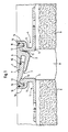
- Fig. 1 eine Vorrichtung mit einer zweiteiligen Überbrückungseinheit und zwei einteiligen Verankerungseinheiten;
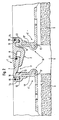
- Fig. 2 eine Vorrichtung gemäß Fig. 1, jedoch mit zwei zweiteiligen Verankerungseinheiten;
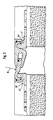
- Fig. 3 eine Vorrichtung mit einer konkav gebogenen Überbrückungseinheit;
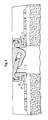
- Fig. 4 eine Vorrichtung mit einer konvex gebogenen Überbrückungseinheit.
- 1 shows a device with a two-part bridging unit and two one-part anchoring units;
- FIG. 2 shows a device according to FIG. 1, but with two two-part anchoring units;
- 3 shows a device with a concavely curved bridging unit;
- Fig. 4 shows a device with a convex bridging unit.
Die Vorrichtung gemäß Fig. 1 besteht aus einer Überbrückungseinheit 1, die aus zwei Brückengliedern 2 und 3 zusammengesetzt ist, und zwei Verankerungseinheiten 4, die jeweils aus einem Winkelprofil 5 gebildet sind.1 consists of a bridging unit 1, which is composed of two
Das Brückenglied 2 weist eine Nut 6 auf, worin eine Feder 7 des Brückenglieds 3 je nach dem Breitenzustand einer Nut 8 mehr oder weniger tief teleskopartig eingreift. Durch die Nut 8 sind zwei Teile 9 eines abgebrochen dargestellten Bauwerksbodens so voneinander getrennt, daß die Teile sich unabhängig voneinander dreidimensional verlagern können.The
Über einen bogenförmig nach unten weisenden Randstreifen 10 ist das Brückenglied 2 bzw. 3 gelenkig mit einem der Verankerungswinkel 5 verbunden. Dazu ist in einem vertikal nach oben weisenden Schenkel 12 jedes Verankerungswinkels 5 eine Nut 12 vorgesehen, die einerseits durch ein am Schenkel 11 angeformtes Walzenstück 13 und andererseits durch ein am Schenkel 11 angeformtes Schalenstück 14 begrenzt ist.The
Über die Länge der Vorrichtung reichende Dichtungsschnüre 15 sind in entsprechend profilierte Nuten an der Oberseite der Feder 7 und an der dem Randstreifen 10 zugewandten Seite der Schalenstücke 14 eingelassen, um dadurch die Vorrichtung gegen Spritzwasser dicht auszuführen.
Bei der Vorrichtung gemäß Fig. 2 besteht jeder Verankerungswinkel 4′ aus einem Winkelprofil 5′, auf dessen vertikal nach oben gerichtetem Schenkel 11′ ein Zwischenprofil 16 formschlüssig aufgesetzt ist. Wie im Ausführungsbeispiel gemäß Fig. 1 der Schenkel 11 ist im Ausführungsbeispiel gemäß Fig. 2 das Zwischenprofil 16 in gleicher Weise mit einer Nut 12 versehen, die seitlich durch ein Walzenstück 13 und ein Schalenstück 14 begrenzt ist.2, each anchoring angle 4 'consists of an angle profile 5', on the vertically upward leg 11 ', an
Bei der Vorrichtung gemäß den Fig. 3 und 4 entsprechen die Verankerungseinheiten 4˝ bis auf eine gedrungenere Ausbildung der Schenkel 11˝ der Winkelprofile 5˝ denen im Ausführungsbeispiel der Fig. 1. Die Querschnittsmittelachsen der Nut 6 und der Feder 7 verlaufen jedoch abweichend von den in den Fig. 1 und 2 dargestellten Ausführungsbeispielen nicht geradlinig, sondern von oben betrachtet in Fig. 1 konkav und in Fig. 4 konvex entsprechend einem Radius R.In the device according to FIGS. 3 and 4 correspond the
Claims (6)
Priority Applications (1)
| Application Number | Priority Date | Filing Date | Title |
|---|---|---|---|
| AT89110079T ATE66993T1 (en) | 1988-08-26 | 1989-06-03 | DEVICE FOR BRIDGING EXPANSION AND MOVEMENT JOINTS. |
Applications Claiming Priority (2)
| Application Number | Priority Date | Filing Date | Title |
|---|---|---|---|
| DE3828980A DE3828980A1 (en) | 1988-08-26 | 1988-08-26 | DEVICE FOR BRIDGING EXPANSION AND MOVEMENT JOINTS |
| DE3828980 | 1988-08-26 |
Publications (3)
| Publication Number | Publication Date |
|---|---|
| EP0356628A2 true EP0356628A2 (en) | 1990-03-07 |
| EP0356628A3 EP0356628A3 (en) | 1990-03-21 |
| EP0356628B1 EP0356628B1 (en) | 1991-09-04 |
Family
ID=6361647
Family Applications (1)
| Application Number | Title | Priority Date | Filing Date |
|---|---|---|---|
| EP89110079A Expired - Lifetime EP0356628B1 (en) | 1988-08-26 | 1989-06-03 | Device for covering expansion and settlement joints |
Country Status (7)
| Country | Link |
|---|---|
| US (1) | US4901495A (en) |
| EP (1) | EP0356628B1 (en) |
| AT (1) | ATE66993T1 (en) |
| CA (1) | CA1315516C (en) |
| DE (2) | DE3828980A1 (en) |
| ES (1) | ES2026717T3 (en) |
| GR (1) | GR3002782T3 (en) |
Cited By (1)
| Publication number | Priority date | Publication date | Assignee | Title |
|---|---|---|---|---|
| CN111648233A (en) * | 2020-05-26 | 2020-09-11 | 中冶南方城市建设工程技术有限公司 | Join together wide bridge joint and prevent subsiding board device |
Families Citing this family (19)
| Publication number | Priority date | Publication date | Assignee | Title |
|---|---|---|---|---|
| ATE87685T1 (en) * | 1989-02-06 | 1993-04-15 | Robert Warthmann | ROLLER CLOSURE ROAD CROSSING, PARTICULARLY FOR DILATION JOINTS OF BRIDGES. |
| US5060439A (en) * | 1990-06-19 | 1991-10-29 | Watson Bowman Acme Corp. | Expansion joint cover assemblies |
| DE29702207U1 (en) * | 1996-05-02 | 1997-04-24 | Modenplast Gmbh | Elastic joint compensation profile |
| GB2325262B (en) * | 1997-05-12 | 2001-05-02 | Kvaerner Cementation Found Ltd | Hydrophilic waterbar for diaphragm wall joints |
| US6663159B2 (en) | 2001-07-20 | 2003-12-16 | Wells Cargo, Inc. | Flexible mount system |
| EP1573213A4 (en) * | 2002-10-22 | 2006-12-13 | Sashlite Llc | Grid muntin retaining clips for muntins |
| US7354219B2 (en) * | 2004-08-20 | 2008-04-08 | Leonberg Douglas E | Multi-seal waterproof expansion joint for roadways |
| DE202005004624U1 (en) * | 2005-03-19 | 2005-07-21 | Herm. Friedr. Künne Gmbh & Co. | Profile rail system |
| EP1913213A1 (en) * | 2005-08-08 | 2008-04-23 | Kronospan Technical Company Ltd. | Flush profiled expansion element |
| KR100994026B1 (en) * | 2010-04-15 | 2010-11-11 | 김은주 | Anti expansion joint bridge |
| CN102691261A (en) * | 2012-05-27 | 2012-09-26 | 张保忠 | Telescopic device of rail transit bridge |
| DE102012107901B3 (en) * | 2012-08-28 | 2013-09-19 | Migua Fugensysteme Gmbh & Co. Kg | Joint profile for a movement joint |
| ITBO20120508A1 (en) * | 2012-09-21 | 2014-03-22 | Joint S R L | EXPANSION JOINT FOR BUILDING |
| DE102016105197A1 (en) * | 2016-03-21 | 2017-09-21 | Migua Fugensysteme Gmbh | Assembly tool for a joint bridging device |
| AU2017202547A1 (en) * | 2016-04-20 | 2017-11-09 | Underwood Companies Holdings Pty Ltd | Improvements in or in relation to expansion joints |
| ES2877370T3 (en) | 2019-01-14 | 2021-11-16 | Migua Fugensysteme Gmbh | Junction bridge device |
| DE202019100165U1 (en) | 2019-01-14 | 2020-04-15 | Migua Fugensysteme Gmbh & Co. Kg | Joint bridging device |
| DE102021102710A1 (en) | 2021-02-05 | 2022-08-11 | Mageba Services & Technology Ag | structure |
| DE102021102703A1 (en) | 2021-02-05 | 2022-08-11 | Mageba Services & Technology Ag | structure |
Citations (3)
| Publication number | Priority date | Publication date | Assignee | Title |
|---|---|---|---|---|
| DE1945534A1 (en) * | 1968-09-11 | 1970-09-03 | Vredestein Rubber | Device for sealing at the top of the space between the ends of a bridge or viaduct and an end abutment and / or pillar |
| DE3015011A1 (en) * | 1980-04-18 | 1981-10-22 | Donau-Eisen Stahlbau Gmbh, 8070 Ingolstadt | Heavy load expansion joint spanning unit - has top of edge clamped support rail meeting bridging rail bottom and includes waterproof diaphragm |
| DE3529877C1 (en) * | 1985-08-21 | 1987-09-10 | Schulte Stemmerk Kg | Apparatus for bridging expansion joints |
Family Cites Families (2)
| Publication number | Priority date | Publication date | Assignee | Title |
|---|---|---|---|---|
| CA1221018A (en) * | 1983-05-02 | 1987-04-28 | H.M. Robert Labelle | Hinged closure panel |
| DE3518507A1 (en) * | 1984-07-18 | 1986-11-27 | P. Schulte-Stemmerk KG für Industrie und Handel, 4100 Duisburg | Sealing device |
-
1988
- 1988-08-26 DE DE3828980A patent/DE3828980A1/en not_active Withdrawn
-
1989
- 1989-06-03 EP EP89110079A patent/EP0356628B1/en not_active Expired - Lifetime
- 1989-06-03 AT AT89110079T patent/ATE66993T1/en not_active IP Right Cessation
- 1989-06-03 DE DE8989110079T patent/DE58900261D1/en not_active Expired - Lifetime
- 1989-06-03 ES ES198989110079T patent/ES2026717T3/en not_active Expired - Lifetime
- 1989-07-10 US US07/377,330 patent/US4901495A/en not_active Expired - Lifetime
- 1989-08-25 CA CA000609480A patent/CA1315516C/en not_active Expired - Fee Related
-
1991
- 1991-09-25 GR GR91400860T patent/GR3002782T3/en unknown
Patent Citations (3)
| Publication number | Priority date | Publication date | Assignee | Title |
|---|---|---|---|---|
| DE1945534A1 (en) * | 1968-09-11 | 1970-09-03 | Vredestein Rubber | Device for sealing at the top of the space between the ends of a bridge or viaduct and an end abutment and / or pillar |
| DE3015011A1 (en) * | 1980-04-18 | 1981-10-22 | Donau-Eisen Stahlbau Gmbh, 8070 Ingolstadt | Heavy load expansion joint spanning unit - has top of edge clamped support rail meeting bridging rail bottom and includes waterproof diaphragm |
| DE3529877C1 (en) * | 1985-08-21 | 1987-09-10 | Schulte Stemmerk Kg | Apparatus for bridging expansion joints |
Cited By (1)
| Publication number | Priority date | Publication date | Assignee | Title |
|---|---|---|---|---|
| CN111648233A (en) * | 2020-05-26 | 2020-09-11 | 中冶南方城市建设工程技术有限公司 | Join together wide bridge joint and prevent subsiding board device |
Also Published As
| Publication number | Publication date |
|---|---|
| ES2026717T3 (en) | 1992-05-01 |
| ATE66993T1 (en) | 1991-09-15 |
| EP0356628B1 (en) | 1991-09-04 |
| DE3828980A1 (en) | 1990-03-01 |
| GR3002782T3 (en) | 1993-01-25 |
| EP0356628A3 (en) | 1990-03-21 |
| DE58900261D1 (en) | 1991-10-10 |
| CA1315516C (en) | 1993-04-06 |
| US4901495A (en) | 1990-02-20 |
Similar Documents
| Publication | Publication Date | Title |
|---|---|---|
| EP0356628B1 (en) | Device for covering expansion and settlement joints | |
| EP0336113B1 (en) | Expansion joint cover | |
| DE10349932A1 (en) | Floor profile assembly for bridging gap between floor coverings has base profile and cover profile with connecting web unit with ball and socket articulated join for adapting to different heights | |
| DE2323162A1 (en) | BUILDING | |
| CH666925A5 (en) | JOINT BRIDGE CONSTRUCTION FOR BRIDGE-LIKE CONSTRUCTIONS. | |
| DD238726A5 (en) | GUIDANCE APPARATUS OF A SHOE, AND SHOE AND SURFACE ADJUSTED TO THIS DEVICE | |
| EP0391149B2 (en) | Portable bridge and system for placing the bridge | |
| DE2738429C2 (en) | Joint sealing profile made of plastic to close a joint | |
| DE202014102976U1 (en) | Wheelchair crossing | |
| DE2011205A1 (en) | Plastic profile | |
| DE3005135A1 (en) | TUBE CONSTRUCTION DEVICE | |
| DE3510945A1 (en) | SUPPORTING DEVICE FOR INSULATION AND FACADE CLEANING | |
| DE19703558B4 (en) | Bar equipment for a scaffolding system | |
| DE102005058087A1 (en) | Cover device for floor joints has two bridging units each with two layers of projection such that each projection on one layer is in laminar contact with projection on other layer | |
| DE69832906T2 (en) | A cover | |
| DE3826514C1 (en) | Profile arrangement for spanning a settlement joint | |
| EP2904161A1 (en) | Slot drain | |
| DE2851941C2 (en) | Machine track for roller cutting machines attached to the face of a face conveyor | |
| WO2012052012A2 (en) | Component connection, support structure, in particular bridge, and method for connecting components | |
| EP3748099B1 (en) | Awning | |
| DE4143268A1 (en) | Spirit level for manual building worker - has extension body guided in basic body contg. bubble with recess in basic body corresp to extension body guide surfaces | |
| DE8423936U1 (en) | DEVICE FOR CLOSING A JOINT WITH AN ELASTIC BRIDGE PROFILE | |
| DE7919389U1 (en) | JOINT COVER DEVICE | |
| DE10032638C2 (en) | Device for holding a bar on a carrier | |
| EP3477016A1 (en) | Variable device for covering joints |
Legal Events
| Date | Code | Title | Description |
|---|---|---|---|
| PUAI | Public reference made under article 153(3) epc to a published international application that has entered the european phase |
Free format text: ORIGINAL CODE: 0009012 |
|
| PUAL | Search report despatched |
Free format text: ORIGINAL CODE: 0009013 |
|
| AK | Designated contracting states |
Kind code of ref document: A2 Designated state(s): AT BE CH DE ES FR GB GR IT LI LU NL SE |
|
| AK | Designated contracting states |
Kind code of ref document: A3 Designated state(s): AT BE CH DE ES FR GB GR IT LI LU NL SE |
|
| 17P | Request for examination filed |
Effective date: 19900214 |
|
| 17Q | First examination report despatched |
Effective date: 19901211 |
|
| GRAA | (expected) grant |
Free format text: ORIGINAL CODE: 0009210 |
|
| AK | Designated contracting states |
Kind code of ref document: B1 Designated state(s): AT BE CH DE ES FR GB GR IT LI LU NL SE |
|
| REF | Corresponds to: |
Ref document number: 66993 Country of ref document: AT Date of ref document: 19910915 Kind code of ref document: T |
|
| REF | Corresponds to: |
Ref document number: 58900261 Country of ref document: DE Date of ref document: 19911010 |
|
| ET | Fr: translation filed | ||
| ITF | It: translation for a ep patent filed |
Owner name: STUDIO JAUMANN |
|
| GBT | Gb: translation of ep patent filed (gb section 77(6)(a)/1977) | ||
| REG | Reference to a national code |
Ref country code: ES Ref legal event code: FG2A Ref document number: 2026717 Country of ref document: ES Kind code of ref document: T3 |
|
| PLBE | No opposition filed within time limit |
Free format text: ORIGINAL CODE: 0009261 |
|
| STAA | Information on the status of an ep patent application or granted ep patent |
Free format text: STATUS: NO OPPOSITION FILED WITHIN TIME LIMIT |
|
| 26N | No opposition filed | ||
| REG | Reference to a national code |
Ref country code: GR Ref legal event code: FG4A Free format text: 3002782 |
|
| EPTA | Lu: last paid annual fee | ||
| EAL | Se: european patent in force in sweden |
Ref document number: 89110079.4 |
|
| REG | Reference to a national code |
Ref country code: CH Ref legal event code: PFA Free format text: MIGUA HAMMERSCHMIDT GMBH TRANSFER- MIGUA FUGENSYSTEME GMBH & CO. KG |
|
| NLT1 | Nl: modifications of names registered in virtue of documents presented to the patent office pursuant to art. 16 a, paragraph 1 |
Owner name: MIGUA FUGENSYSTEME GMBH & CO. KG;MIGUA FUGENSYSTEM |
|
| REG | Reference to a national code |
Ref country code: ES Ref legal event code: PC2A |
|
| REG | Reference to a national code |
Ref country code: FR Ref legal event code: TP |
|
| BECN | Be: change of holder's name |
Effective date: 19970507 |
|
| PGFP | Annual fee paid to national office [announced via postgrant information from national office to epo] |
Ref country code: SE Payment date: 19990409 Year of fee payment: 11 |
|
| PGFP | Annual fee paid to national office [announced via postgrant information from national office to epo] |
Ref country code: LU Payment date: 19990610 Year of fee payment: 11 |
|
| PG25 | Lapsed in a contracting state [announced via postgrant information from national office to epo] |
Ref country code: LU Free format text: LAPSE BECAUSE OF NON-PAYMENT OF DUE FEES Effective date: 20000603 |
|
| PG25 | Lapsed in a contracting state [announced via postgrant information from national office to epo] |
Ref country code: SE Free format text: LAPSE BECAUSE OF NON-PAYMENT OF DUE FEES Effective date: 20000604 |
|
| PGFP | Annual fee paid to national office [announced via postgrant information from national office to epo] |
Ref country code: CH Payment date: 20000626 Year of fee payment: 12 |
|
| EUG | Se: european patent has lapsed |
Ref document number: 89110079.4 |
|
| PG25 | Lapsed in a contracting state [announced via postgrant information from national office to epo] |
Ref country code: LI Free format text: LAPSE BECAUSE OF NON-PAYMENT OF DUE FEES Effective date: 20010630 Ref country code: CH Free format text: LAPSE BECAUSE OF NON-PAYMENT OF DUE FEES Effective date: 20010630 |
|
| REG | Reference to a national code |
Ref country code: GB Ref legal event code: IF02 |
|
| REG | Reference to a national code |
Ref country code: CH Ref legal event code: PL |
|
| PGFP | Annual fee paid to national office [announced via postgrant information from national office to epo] |
Ref country code: GR Payment date: 20050524 Year of fee payment: 17 |
|
| PGFP | Annual fee paid to national office [announced via postgrant information from national office to epo] |
Ref country code: BE Payment date: 20050817 Year of fee payment: 17 |
|
| PG25 | Lapsed in a contracting state [announced via postgrant information from national office to epo] |
Ref country code: BE Free format text: LAPSE BECAUSE OF NON-PAYMENT OF DUE FEES Effective date: 20060630 |
|
| PGFP | Annual fee paid to national office [announced via postgrant information from national office to epo] |
Ref country code: NL Payment date: 20070523 Year of fee payment: 19 |
|
| PGFP | Annual fee paid to national office [announced via postgrant information from national office to epo] |
Ref country code: AT Payment date: 20070614 Year of fee payment: 19 |
|
| BERE | Be: lapsed |
Owner name: *MIGUA FUGENSYSTEME G.M.B.H. & CO. K.G. Effective date: 20060630 |
|
| PGFP | Annual fee paid to national office [announced via postgrant information from national office to epo] |
Ref country code: FR Payment date: 20070608 Year of fee payment: 19 |
|
| PGFP | Annual fee paid to national office [announced via postgrant information from national office to epo] |
Ref country code: IT Payment date: 20080625 Year of fee payment: 20 |
|
| PG25 | Lapsed in a contracting state [announced via postgrant information from national office to epo] |
Ref country code: GR Free format text: LAPSE BECAUSE OF NON-PAYMENT OF DUE FEES Effective date: 20070104 |
|
| PGFP | Annual fee paid to national office [announced via postgrant information from national office to epo] |
Ref country code: ES Payment date: 20080717 Year of fee payment: 20 Ref country code: DE Payment date: 20080425 Year of fee payment: 20 |
|
| PGFP | Annual fee paid to national office [announced via postgrant information from national office to epo] |
Ref country code: GB Payment date: 20080604 Year of fee payment: 20 |
|
| NLV4 | Nl: lapsed or anulled due to non-payment of the annual fee |
Effective date: 20090101 |
|
| REG | Reference to a national code |
Ref country code: FR Ref legal event code: ST Effective date: 20090228 |
|
| PG25 | Lapsed in a contracting state [announced via postgrant information from national office to epo] |
Ref country code: AT Free format text: LAPSE BECAUSE OF NON-PAYMENT OF DUE FEES Effective date: 20080603 |
|
| PG25 | Lapsed in a contracting state [announced via postgrant information from national office to epo] |
Ref country code: NL Free format text: LAPSE BECAUSE OF NON-PAYMENT OF DUE FEES Effective date: 20090101 |
|
| REG | Reference to a national code |
Ref country code: GB Ref legal event code: PE20 Expiry date: 20090602 |
|
| REG | Reference to a national code |
Ref country code: ES Ref legal event code: FD2A Effective date: 20090604 |
|
| PG25 | Lapsed in a contracting state [announced via postgrant information from national office to epo] |
Ref country code: FR Free format text: LAPSE BECAUSE OF NON-PAYMENT OF DUE FEES Effective date: 20080630 |
|
| PG25 | Lapsed in a contracting state [announced via postgrant information from national office to epo] |
Ref country code: ES Free format text: LAPSE BECAUSE OF EXPIRATION OF PROTECTION Effective date: 20090604 |
|
| PG25 | Lapsed in a contracting state [announced via postgrant information from national office to epo] |
Ref country code: GB Free format text: LAPSE BECAUSE OF EXPIRATION OF PROTECTION Effective date: 20090602 |