US6663159B2 - Flexible mount system - Google Patents
Flexible mount system Download PDFInfo
- Publication number
- US6663159B2 US6663159B2 US09/910,112 US91011201A US6663159B2 US 6663159 B2 US6663159 B2 US 6663159B2 US 91011201 A US91011201 A US 91011201A US 6663159 B2 US6663159 B2 US 6663159B2
- Authority
- US
- United States
- Prior art keywords
- elongated
- mounting bracket
- thermally dynamic
- dynamic sheet
- thermally
- Prior art date
- Legal status (The legal status is an assumption and is not a legal conclusion. Google has not performed a legal analysis and makes no representation as to the accuracy of the status listed.)
- Expired - Lifetime
Links
Images


Classifications
-
- B—PERFORMING OPERATIONS; TRANSPORTING
- B60—VEHICLES IN GENERAL
- B60J—WINDOWS, WINDSCREENS, NON-FIXED ROOFS, DOORS, OR SIMILAR DEVICES FOR VEHICLES; REMOVABLE EXTERNAL PROTECTIVE COVERINGS SPECIALLY ADAPTED FOR VEHICLES
- B60J7/00—Non-fixed roofs; Roofs with movable panels, e.g. rotary sunroofs
- B60J7/08—Non-fixed roofs; Roofs with movable panels, e.g. rotary sunroofs of non-sliding type, i.e. movable or removable roofs or panels, e.g. let-down tops or roofs capable of being easily detached or of assuming a collapsed or inoperative position
- B60J7/10—Non-fixed roofs; Roofs with movable panels, e.g. rotary sunroofs of non-sliding type, i.e. movable or removable roofs or panels, e.g. let-down tops or roofs capable of being easily detached or of assuming a collapsed or inoperative position readily detachable, e.g. tarpaulins with frames, or fastenings for tarpaulins
- B60J7/102—Readily detachable tarpaulins, e.g. for utility vehicles; Frames therefor
- B60J7/104—Fastening means for tarpaulins
Definitions
- the present invention relates to an apparatus for providing a flexible mount assembly for securing at least one thermally dynamic article subject to significant thermal expansion.
- thermally dynamic materials such as polyvinyl chloride, polypropylene, polyethylene, and the like have an expansion coefficient of about six thousandths of an inch per inch/° F. Accordingly, when mounting relatively large pieces of thermally dynamic material, that is, ones on the order of about one and one half feet long or longer, the thermal expansion of the piece can become a problem if mounted to a material having a substantially different coefficient of thermal expansion, particularly for products that are used outdoors. For these reasons, thermally dynamic materials have not been typically used to fabricate the tops of trailers or similar articles because it has been difficult to accommodate thermal expansion and provide a proper seal from moisture between the top and the less thermally dynamic conjoined sides.
- materials having significantly smaller coefficients of thermal expansion have been used for the fabrication of tops of trailers or similar articles.
- Such materials typically included fiberglass or sheet metal. While fiberglass materials tend to serve their function, they are brittle, cumbersome to cut and form due to their fibrous nature, and more expensive than is desirable. Sheet metal is typically less brittle and easier to work with than fiberglass materials; however, it is more costly than is desirable for many applications. Thus, there exists a need for a mounting system which can accommodate the thermal expansion inherent with the use of larger pieces of relatively inexpensive thermoplastics.
- U.S. Pat. No. 3,363,383 issued to LaBarge is directed to a flexible joint seal between two or more substantially rigid structural members. It includes an elastomeric element adapted for sealing joints between two or more rigid panels. The panels are rigidly secured against suitable conventional supporting or framing elements such as the structural angles 44 by blind rivets 46 .
- the sealing elements of the LeBarge patent act as a seal and closure between the rigidly mounted panels rather than a flexible mounting system for securing a thermally dynamic material.
- One object of an embodiment of the present invention is to provide a flexible mounting system for the mounting or conjoining of at least one of a thermally expandable and thermally inert structure, such as the conjunction of a thermally dynamic top covering of a trailer to its corresponding side walls.
- Another object of an embodiment of the present invention is to provide an air and water impermeable flexible mounting system for the mounting or conjoining of at least one of a thermally dynamic structure, having a relatively large coefficient of thermal expansion, and a thermally inert structure. Additionally, such an embodiment also allows for the flexible mounting or conjoining of two thermally dynamic structures having similar, yet great, coefficients of thermal expansion.
- Still another object of an embodiment of the present invention is to provide a flexible mounting system for the mounting or conjoining of a plurality of at least one of a structure, being thermally inert, and thermally dynamic sheet, having a relatively large coefficient of thermal expansion, to another thermally dynamic sheet or thermally inert structure.
- a first embodiment of the invention is directed to a mounting system for securing a thermally dynamic sheet to at least one structure, which includes an elongated track affixed to the thermally dynamic sheet or the structure.
- An elongated flexible mounting bracket is affixed to the thermally dynamic sheet or the structure.
- the elongated flexible mounting bracket has a foot portion adapted to slidably mount in the elongated track to provide sliding movement of the elongated flexible mounting bracket along a first axis of the thermally dynamic sheet or the structure.
- the system of the invention can accommodate thermal expansion/contraction in the first axis by sliding movement of the foot in the bracket and in the direction transverse to the first axis by flexing of the flexible mounting bracket.
- the terms “slidably retained,” “slidably mounted” and “sliding movement” as used herein mean that the flexible bracket can at least “creep” along the track to accommodate thermal expansion or contraction in at least one axis of the sheet, and do not require that the foot is capable of freely sliding within the track.
- the flexible mounting bracket include a clamping portion for encompassing at least one edge of the thermally dynamic sheet or the structure.
- FIG. 1 Another embodiment of the present invention is directed to a mounting system (for thermally dynamic trailer covering including, a trailer with a side wall and end wall.
- a thermally dynamic covering is mounted to the trailer side wall and end wall by an elongated track affixed to the trailer side wall, the trailer end wall, or the thermally dynamic covering.
- An elongated flexible mounting bracket is affixed to the trailer side wall, the trailer end wall, or the thermally dynamic covering.
- the elongated flexible mounting bracket has a foot portion adapted to slidably mount in the elongated track.
- a still further embodiment of the invention is directed to a method of mounting a thermally dynamic sheet to a structure, including the steps of: (a) adhering an elongated flexible mounting bracket having a foot portion to the thermally dynamic sheet or the structure to form an adhered assembly; (b) placing the adhered assembly in contact with the thermally dynamic sheet or structure which lacks the adhered flexible mounting bracket; (c) positioning an elongated track along the thermally dynamic sheet or structure which lacks the adhered flexible mounting bracket such that the foot portion of the flexible elongated mounting bracket is retained within the track; and (d) mounting the elongated track to the thermally dynamic sheet or the structure which lacks the adhered flexible mounting bracket such that the foot portion is slidably mounted within the elongated track.
- FIG. 1 is a perspective of a trailer having side walls and a top covering secured in accordance with one embodiment of the mounting system of the invention
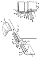
- FIG. 2 is an enlarged, fragmentary, perspective view of the corner of the trailer with the mounting system of FIG. 1;
- FIG. 3 is an exploded perspective view of the mounting system of FIG. 1;
- FIG. 4 is a cross-sectional view taken along lines 4 — 4 of FIG. 3, showing the mounting system of FIG. 1;
- FIG. 5 is a fragmentary perspective view of another embodiment of the mounting system of the present invention.
- FIG. 6 is a schematic top view of another embodiment of the mounting system of the invention.
- a Flexible Mounting System may be used to flexibly mount a relatively thermally dynamic covering 2 , such as a trailer roof, to a trailer 4 with relatively thermally inert side walls 6 and end walls 8 .
- a relatively thermally dynamic covering 2 such as a trailer roof
- a trailer 4 with relatively thermally inert side walls 6 and end walls 8 .
- an elongated track 10 is provided and is preferably made of a rigid material such as metal, hardened plastic or rubber and is either detachably or permanently affixed to the trailer side walls 6 and end walls 8 at fastening points 12 by any standard fasteners such as a nut and bolt 13 as shown in FIGS. 3 and 4.
- the elongated track 10 may be mounted to the trailer side walls 6 and end walls 8 using, but not limited to, adhesives, screws, bolts, rivets, and spot-welds. Additionally, it is contemplated that the fastening of the elongated track 10 to the trailer may wrap continually around radius corner portions 9 formed between side walls 6 and end walls 8 as shown in FIG. 2 which can yield an airtight, water-tight mount.
- the elongated track 10 may also be mounted to the thermally dynamic covering 2 of the trailer 4 in which case the track must be selected from a material having a similar co-efficient of thermal expansion as the covering.
- the orientation of the elongated flexible mounting bracket would be exchanged with the track such that the mounting bracket would be adhered to the thermally inert trailer side walls 6 and end walls 8 and the track would be mounted to the thermally dynamic covering 2 .
- the track may be integrally molded into the dynamic covering provided that a sufficiently strong plastic resin is chosen.
- the trailer side walls 6 and end walls 8 typically have relatively small coefficients of thermal expansion compared to the thermally dynamic covering 2 , and may consist of materials such as sheet metals (including steel, aluminum, tin, alloys thereof, and fiberglass), relatively thermally inert plastics, and fiberglass.
- the Flexible Mounting System's, elongated track 10 includes a base portion 14 for attachment to another structure and a hooked portion 16 for receiving an elongated flexible mounting bracket 18 .
- the elongated flexible mounting bracket 18 is slidable within the hook portion 16 of the track 10 primarily to accommodate longitudinal expansion or contraction of the thermodynamic covering 2 .
- the elongated flexible mounting bracket 18 in turn is adhered with a suitable adhesive, preferably 3M Brand Contact Adhesive, to the thermally dynamic covering 2 or similar structural member which is subject to thermal expansion.
- the thermally dynamic covering 2 is preferably made from ABS but may be made of other thermoplastic selected from the major families of polyethylene, polypropylene, polyvinyl chloride, other polystyrenes, acrylics, nylons, PET, cellulosics and/or co-polymers or blends of such materials. Additionally, other forms of adhering the dynamic covering 2 to the mounting bracket 18 such as melt-bonding, spot welding, or utilizing fasteners are also contemplated. It is further contemplated that such fastening of the elongated flexible mounting bracket 18 to the thermally dynamic covering 2 may be continuous around corners 9 of the trailer 4 .
- the elongated flexible mounting bracket 18 is preferably made of EPDM, but may be made from other rubber-like materials including those polymers used in the sheet rubber industry such as, natural rubber, Styrene Butadiene Rubber, Neoprene, Ethylene-Propylene, Hypalon, and Viton, which can flex through significant distances to accommodate lateral thermal expansion and contraction of the thermodynamic covering 2 .
- the elongated flexible mounting bracket 18 includes a foot portion 20 that is shaped and dimensioned to fit within, and slidably mount in the hook portion 16 of the track 10 .
- a hinge portion 22 of the flexible mounting bracket 18 consisting of a first angled wall 24 and a second angled wall 26 , which are joined at a hinge line 28 .
- the hinge portion 22 flexes to accommodate the expansion and contraction of the thermally dynamic covering 2 or trailer side walls 6 and end walls 8 .
- Extending from the second angled wall 26 is a C-shaped clamping portion 30 , which encompasses a downward flange 32 of the thermally dynamic covering 2 .
- An inward extension 34 of the clamping portion 30 engages the interior of the downwardly extending flange 32 of the thermally dynamic covering 2 .
- the elongated flexible mounting bracket 18 is pressed downwardly into the clamp portion 30 and adhered to the thermally dynamic covering 2 via suitable adhesive.
- the thermally dynamic covering 2 and flexible mounting bracket 18 are placed over the trailer frame.
- the trailer side wall 6 and end walls 8 are secured to the frame.
- the elongated track is positioned on the side wall 6 and end walls 8 such that the foot portion 20 of the flexible mounting bracket 18 is slidably retained within the hook portion 16 of the elongated track 10 .
- the elongated track is then mounted to the side wall and end walls, preferably as a continuous strip, such that the flexible mounting bracket 18 is slidably mounted in the elongated track 10 thereby forming and air-tight and water-tight flexible mounting system.
- the assembly of the trailer would necessarily change since the track could not be positioned and then fastened over the foot of the bracket.
- the foot of the flexible mounting bracket would be slid into the integral track in the thermally dynamic covering.
- the covering would be placed over the trailer frame and the upper edge of the side walls and/or end walls would be pressed into the clamp portion of the bracket and the adhesive would be applied to the bracket and edge.
- the Flexible Mounting System may act to provide an impermeable seal while also securing, mounting or conjoining, for example, two separate structures, at least one being a relatively thermally dynamic sheet having a relatively large coefficient of thermal expansion, and the other being a relatively thermally inert structure. Additionally, it is also contemplated that the system of the invention could be used to conjoin two similar structures, both have relatively large coefficients of thermal expansion.
- structure 136 is preferably formed from a relatively thermally inert and rigid materials such as steel, tin, aluminum, copper, bronze, alloys thereof, relatively thermally inert plastics, or fiberglass.
- Elongated track 110 is attached to structure 136 in the same manner as previously described in the embodiment of FIGS. 1-4.
- Elongated track 110 is preferably made of a rigid material such as metal, hardened plastic or rubber and may be detachably or permanently affixed at fastening points 112 to structure 136 by any standard fastener such as adhesives, screws, bolts, rivets, melt welds or spot-welds. It is contemplated that structure 136 may also be one of a thermally dynamic nature having a relatively large coefficient of thermal expansion.
- the embodiment of FIG. 5 includes detachable or permanent adhesion of an elongated flexible mounting bracket 118 to a thermally dynamic sheet 138 , having a large coefficient of thermal expansion.
- the sheet is preferably made of thermoplastics which includes the major families of polyethylene, polypropylene, polyvinyl chloride, polystyrene, acrylics, nylons, cellulosics, and co-polymers or blends of such materials.
- the elongated flexible mounting bracket 118 is preferably composed of one of the rubber-like materials described above which can flex through significant distances to accommodate lateral thermal expansion and contraction of the thermally dynamic sheet 138 .
- the elongated flexible mounting bracket 118 includes a foot portion (not shown) that is shaped and dimensioned to be slidably retained within, and slidably mount to, the hook portion 116 .
- the elongated flexible mounting bracket 118 also has, extending above the foot, a hinge portion 122 consisting of a first angled wall 124 and a second angled wall 126 , which forms a hinge line 128 and flexes to accommodate the expansion and contraction of the thermally dynamic sheet 138 .
- extending from the second angled wall 126 is a C-shaped clamping portion similar to that shown in FIG. 4, which encompasses the thermally dynamic sheet 138 .
- thermally dynamic sheet 138 engages the interior of the thermally dynamic sheet 138 .
- Internal extension (not shown) engages the interior of the thermally dynamic sheet 138 .
- Such an elongated 15 flexible mounting bracket 118 may be adhered to either the thermally dynamic sheet 138 or structure 136 in a manner similar to that discussed above for the embodiment of FIGS. 1-4.
- the present invention may also be used to provide an impermeable flexible mounting system for the screening, mounting or conjoining of a plurality of structures, at least one of which is relatively thermally inert, and another of which is thermally dynamic.
- the embodiment a shown in FIG. 6 details the detachable or permanent conjunction of an elongated track 210 to each side of a thermally dynamic sheet 238 .
- the elongated track 210 may consist of, a rigid material such as metal, hardened plastic or rubber and may be affixed to the thermally dynamic sheet 238 using any standard fasteners including, adhesives, screws, bolts, rivets, melt welds, and spot-welds.
- the thermally dynamic sheet 238 may consist of materials such as those described above with reference to the embodiments of FIGS. 1-5. It is also contemplated that the elongated track 10 may be affixed to each side of a thermally inert structure. While FIG. 6 demonstrates that individual pieces of elongated track 210 are attached to each side of the thermally dynamic sheet 238 , it is also anticipated that the elongated track 210 may be continuously affixed to the thermally dynamic sheet 238 around corners 209 .
- FIG. 6 also discloses the adhesion of an elongated flexible mounting bracket 218 to at least one side of a plurality of structures 236 , each having a side that will abut a portion of the elongated track 210 affixed on each side of thermally dynamic sheet 238 .
- the elongated flexible mounting bracket 218 is adhered to the structures 236 in a manner similar to that of FIGS. 1-4.
- the thermally dynamic sheet has the mounting track affixed to it, the track should be selected from materials having a similar co-efficient of thermal expansion to the track 210 .
- the track may be integrally molded into the thermally dynamic sheet 228 .
- the flexible mounting bracket 218 is preferably constructed of a rubber-like materials such as those discussed above with reference to the other embodiments.
- the elongated flexible mounting bracket 218 additionally consists of a foot portion (not shown) that is shaped and dimensioned to be slidably retained within, and slidably mount to a hook portion of the track 210 .
- the elongated flexible mounting bracket 218 also has, extending above the foot, a hinge portion 222 consisting of a first angled wall and second angled wall (not shown), which forms a hinge line 228 and flexes to accommodate the expansion and contraction of the thermally dynamic sheet 238 .
- a hinge portion 222 consisting of a first angled wall and second angled wall (not shown), which forms a hinge line 228 and flexes to accommodate the expansion and contraction of the thermally dynamic sheet 238 .
- extending from the second angled wall is a C-shaped clamping portion similar to that shown in FIG. 4, which encompasses the structure 236
- thermally dynamic sheet 238 may have a combination of elongated tracks 210 and elongated flexible mounting brackets 218 affixed to its sides.
- the embodiment demonstrates that individual pieces of elongated flexible mounting bracket 218 are attached to each side of the structures 236 , it is also anticipated that the elongated flexible mounting brackets 218 may be continuously affixed to each structure 236 .
- structures 236 may have, the orientation of the brackets and tracks reversed whereby instead of elongated flexible mounting brackets, an elongated track is affixed to structures 236 and the flexible mounting bracket is affixed to the sheet 238 .
- structures 236 may also be thermally dynamic and have affixed thereto elongated flexible mounting brackets 218 .
Landscapes
- Engineering & Computer Science (AREA)
- Mechanical Engineering (AREA)
- Roof Covering Using Slabs Or Stiff Sheets (AREA)
- Connection Of Plates (AREA)
Abstract
Description
Claims (30)
Priority Applications (1)
| Application Number | Priority Date | Filing Date | Title |
|---|---|---|---|
| US09/910,112 US6663159B2 (en) | 2001-07-20 | 2001-07-20 | Flexible mount system |
Applications Claiming Priority (1)
| Application Number | Priority Date | Filing Date | Title |
|---|---|---|---|
| US09/910,112 US6663159B2 (en) | 2001-07-20 | 2001-07-20 | Flexible mount system |
Publications (2)
| Publication Number | Publication Date |
|---|---|
| US20030015888A1 US20030015888A1 (en) | 2003-01-23 |
| US6663159B2 true US6663159B2 (en) | 2003-12-16 |
Family
ID=25428327
Family Applications (1)
| Application Number | Title | Priority Date | Filing Date |
|---|---|---|---|
| US09/910,112 Expired - Lifetime US6663159B2 (en) | 2001-07-20 | 2001-07-20 | Flexible mount system |
Country Status (1)
| Country | Link |
|---|---|
| US (1) | US6663159B2 (en) |
Cited By (3)
| Publication number | Priority date | Publication date | Assignee | Title |
|---|---|---|---|---|
| US20060150553A1 (en) * | 2005-01-13 | 2006-07-13 | Erenio Reyes | Control joint |
| US11885138B2 (en) | 2020-11-12 | 2024-01-30 | Clarkwestern Dietrich Building Systems Llc | Control joint |
| USD1026252S1 (en) | 2020-11-12 | 2024-05-07 | Clarkwestern Dietrich Building Systems Llc | Control joint |
Citations (16)
| Publication number | Priority date | Publication date | Assignee | Title |
|---|---|---|---|---|
| US2226886A (en) | 1938-10-14 | 1940-12-31 | Emil Brown | Reglet |
| US2812973A (en) * | 1955-09-27 | 1957-11-12 | Duralite Mfg Company | Commercial vehicle body wall construction |
| US2822588A (en) | 1957-02-04 | 1958-02-11 | C & J Service Inc | Joining strip for plastic sheets |
| US3290077A (en) * | 1964-07-15 | 1966-12-06 | Aluminum Co Of America | Joining and jointed structures |
| US3363383A (en) | 1965-03-08 | 1968-01-16 | Aluminum Co Of America | Joint structures |
| US3888599A (en) | 1974-09-20 | 1975-06-10 | Specialties Const | Expansion joint seal |
| US4007994A (en) | 1975-12-18 | 1977-02-15 | The D. S. Brown Company | Expansion joint with elastomer seal |
| US4063393A (en) * | 1973-05-10 | 1977-12-20 | Toti Andrew J | Panel assembly structure and procedure for assembling same |
| US4063840A (en) | 1977-03-09 | 1977-12-20 | The General Tire & Rubber Company | Expansion joint seal assembly |
| US4140419A (en) | 1977-06-10 | 1979-02-20 | Acme Highway Products Corporation | Molded expansion joint |
| US4774795A (en) | 1983-01-31 | 1988-10-04 | Braun Frank A | Expansion joint |
| US4901495A (en) | 1988-08-26 | 1990-02-20 | Migua Hammerschmidt Gmbh | Expansion joint for bridging spaced floor structures |
| US4965976A (en) | 1989-09-22 | 1990-10-30 | Mm Systems Corporation | End cap for expansion joint |
| US5524394A (en) * | 1993-03-02 | 1996-06-11 | Batesville Casket Company, Inc. | Modular casket display system |
| US5601198A (en) * | 1994-12-12 | 1997-02-11 | Reed; Doris L. | Flexible barrier for a shelf |
| US5791093A (en) * | 1997-03-19 | 1998-08-11 | Goer Manufacturing Company, Inc. | Slatwall panel and method of assembling same |
-
2001
- 2001-07-20 US US09/910,112 patent/US6663159B2/en not_active Expired - Lifetime
Patent Citations (17)
| Publication number | Priority date | Publication date | Assignee | Title |
|---|---|---|---|---|
| US2226886A (en) | 1938-10-14 | 1940-12-31 | Emil Brown | Reglet |
| US2812973A (en) * | 1955-09-27 | 1957-11-12 | Duralite Mfg Company | Commercial vehicle body wall construction |
| US2822588A (en) | 1957-02-04 | 1958-02-11 | C & J Service Inc | Joining strip for plastic sheets |
| US3290077A (en) * | 1964-07-15 | 1966-12-06 | Aluminum Co Of America | Joining and jointed structures |
| US3363383A (en) | 1965-03-08 | 1968-01-16 | Aluminum Co Of America | Joint structures |
| US4114247A (en) * | 1973-05-10 | 1978-09-19 | Toti Andrew J | Method of assembling a panel assembly structure |
| US4063393A (en) * | 1973-05-10 | 1977-12-20 | Toti Andrew J | Panel assembly structure and procedure for assembling same |
| US3888599A (en) | 1974-09-20 | 1975-06-10 | Specialties Const | Expansion joint seal |
| US4007994A (en) | 1975-12-18 | 1977-02-15 | The D. S. Brown Company | Expansion joint with elastomer seal |
| US4063840A (en) | 1977-03-09 | 1977-12-20 | The General Tire & Rubber Company | Expansion joint seal assembly |
| US4140419A (en) | 1977-06-10 | 1979-02-20 | Acme Highway Products Corporation | Molded expansion joint |
| US4774795A (en) | 1983-01-31 | 1988-10-04 | Braun Frank A | Expansion joint |
| US4901495A (en) | 1988-08-26 | 1990-02-20 | Migua Hammerschmidt Gmbh | Expansion joint for bridging spaced floor structures |
| US4965976A (en) | 1989-09-22 | 1990-10-30 | Mm Systems Corporation | End cap for expansion joint |
| US5524394A (en) * | 1993-03-02 | 1996-06-11 | Batesville Casket Company, Inc. | Modular casket display system |
| US5601198A (en) * | 1994-12-12 | 1997-02-11 | Reed; Doris L. | Flexible barrier for a shelf |
| US5791093A (en) * | 1997-03-19 | 1998-08-11 | Goer Manufacturing Company, Inc. | Slatwall panel and method of assembling same |
Cited By (4)
| Publication number | Priority date | Publication date | Assignee | Title |
|---|---|---|---|---|
| US20060150553A1 (en) * | 2005-01-13 | 2006-07-13 | Erenio Reyes | Control joint |
| US7757450B2 (en) * | 2005-01-13 | 2010-07-20 | Dietrich Industries, Inc. | Control joint |
| US11885138B2 (en) | 2020-11-12 | 2024-01-30 | Clarkwestern Dietrich Building Systems Llc | Control joint |
| USD1026252S1 (en) | 2020-11-12 | 2024-05-07 | Clarkwestern Dietrich Building Systems Llc | Control joint |
Also Published As
| Publication number | Publication date |
|---|---|
| US20030015888A1 (en) | 2003-01-23 |
Similar Documents
| Publication | Publication Date | Title |
|---|---|---|
| US8623158B2 (en) | System for mounting objects to polymeric membranes | |
| US9121545B2 (en) | System for mounting objects to polymeric membranes | |
| JP4124960B2 (en) | Improved column round coating equipment | |
| US4081941A (en) | Flexible protective cover sections, assemblies and form system | |
| US4622794A (en) | Panel wall system | |
| US11141928B2 (en) | System for mounting objects to polymeric membranes | |
| US5572843A (en) | Fastening strip for sheet roofing systems | |
| US4075811A (en) | Building roof panel | |
| CA2217914A1 (en) | Apparatus and method of applying building panels to surfaces | |
| US5899027A (en) | Contaminant shield | |
| US9175479B2 (en) | System for mounting objects to polymeric membranes | |
| EP0430667B1 (en) | Cladding panel and system | |
| US6385939B1 (en) | Bullnose cladding system | |
| US20160040431A1 (en) | System for Mounting Objects to Polymeric Membranes | |
| MXPA03001187A (en) | Stiffener construction having a snap-on connector, for use with a wall panel shell in a wall system. | |
| WO2003046311A1 (en) | Concrete placing form | |
| US5784982A (en) | Boat windshield with vertical joint system | |
| US6112340A (en) | Hot tub and spa cover and method of making same | |
| US6663159B2 (en) | Flexible mount system | |
| US3282613A (en) | Panel connector | |
| US5526866A (en) | Tonneau cover fastening system | |
| AU2016200453B2 (en) | Spa cabinet attachment | |
| US3756636A (en) | Joint construction for strip structures | |
| US9611660B2 (en) | Vehicle corner rail assembly | |
| GB2180802A (en) | Box structure |
Legal Events
| Date | Code | Title | Description |
|---|---|---|---|
| AS | Assignment |
Owner name: WELLS CARGO, INC., INDIANA Free format text: ASSIGNMENT OF ASSIGNORS INTEREST;ASSIGNOR:KINKAIDE, JIM;REEL/FRAME:012335/0670 Effective date: 20011016 |
|
| STCF | Information on status: patent grant |
Free format text: PATENTED CASE |
|
| FPAY | Fee payment |
Year of fee payment: 4 |
|
| AS | Assignment |
Owner name: UNIVERSAL TRAILER HOLDINGS CORP., OHIO Free format text: ASSIGNMENT OF ASSIGNORS INTEREST;ASSIGNORS:WELLS CARGO, INC. (INDIANA CORPORATION);WELLS INDUSTRIES, INC.;WELLS CARGO, INC. (ARIZONA CORPORATION);AND OTHERS;REEL/FRAME:023373/0488 Effective date: 20091001 |
|
| FPAY | Fee payment |
Year of fee payment: 8 |
|
| AS | Assignment |
Owner name: UNIVERSAL TRAILER CARGO GROUP, INC., OHIO Free format text: ASSIGNMENT OF ASSIGNORS INTEREST;ASSIGNOR:UNIVERSAL TRAILER HOLDINGS CORP.;REEL/FRAME:027486/0940 Effective date: 20120104 |
|
| AS | Assignment |
Owner name: UNIVERSAL TRAILER CARGO GROUP, INC., OHIO Free format text: RELEASE BY SECURED PARTY;ASSIGNOR:CP II UT COINVESTORS, LLC;REEL/FRAME:027819/0566 Effective date: 20120228 Owner name: UNIVERSAL TRAILER CARGO GROUP, INC., OHIO Free format text: RELEASE BY SECURED PARTY;ASSIGNOR:JPMORGAN CHASE BANK, N.A.;REEL/FRAME:027820/0807 Effective date: 20120227 |
|
| AS | Assignment |
Owner name: WELLS FARGO BANK, NATIONAL ASSOCIATION, CALIFORNIA Free format text: PATENT AND TRADEMARK SECURITY AGREEMENT;ASSIGNOR:UNIVERSAL TRAILER CARGO GROUP, INC.;REEL/FRAME:027876/0119 Effective date: 20111129 |
|
| FEPP | Fee payment procedure |
Free format text: PAT HOLDER NO LONGER CLAIMS SMALL ENTITY STATUS, ENTITY STATUS SET TO UNDISCOUNTED (ORIGINAL EVENT CODE: STOL); ENTITY STATUS OF PATENT OWNER: LARGE ENTITY |
|
| SULP | Surcharge for late payment | ||
| FPAY | Fee payment |
Year of fee payment: 12 |
|
| AS | Assignment |
Owner name: KEYBANK NATIONAL ASSOCIATION, OHIO Free format text: SECURITY INTEREST;ASSIGNORS:UNIVERSAL TRAILER HOLDINGS CORP.;UNIVERSAL TRAILER CORPORATION;UNIVERSAL TRAILER CARGO GROUP, INC.;AND OTHERS;REEL/FRAME:044277/0177 Effective date: 20171127 |
|
| AS | Assignment |
Owner name: UNIVERSAL TRAILER OF OKLAHOMA, LLC, FLORIDA Free format text: RELEASE BY SECURED PARTY;ASSIGNOR:KEYBANK NATIONAL ASSOCIATION;REEL/FRAME:046588/0364 Effective date: 20180803 Owner name: UNIVERSAL TRAILER HOLDINGS CORP., FLORIDA Free format text: RELEASE BY SECURED PARTY;ASSIGNOR:KEYBANK NATIONAL ASSOCIATION;REEL/FRAME:046588/0364 Effective date: 20180803 Owner name: UNIVERSAL TRAILER ACCEPTANCE CORP., FLORIDA Free format text: RELEASE BY SECURED PARTY;ASSIGNOR:KEYBANK NATIONAL ASSOCIATION;REEL/FRAME:046588/0364 Effective date: 20180803 Owner name: SOONER TRAILER MANUFACTURING COMPANY, LLC, FLORIDA Free format text: RELEASE BY SECURED PARTY;ASSIGNOR:KEYBANK NATIONAL ASSOCIATION;REEL/FRAME:046588/0364 Effective date: 20180803 Owner name: UNIVERSAL TRAILER CARGO GROUP, INC., FLORIDA Free format text: RELEASE BY SECURED PARTY;ASSIGNOR:KEYBANK NATIONAL ASSOCIATION;REEL/FRAME:046588/0364 Effective date: 20180803 Owner name: EXISS SOONER, LLC, FLORIDA Free format text: RELEASE BY SECURED PARTY;ASSIGNOR:KEYBANK NATIONAL ASSOCIATION;REEL/FRAME:046588/0364 Effective date: 20180803 Owner name: UNIVERSAL TRAILER CORPORATION, FLORIDA Free format text: RELEASE BY SECURED PARTY;ASSIGNOR:KEYBANK NATIONAL ASSOCIATION;REEL/FRAME:046588/0364 Effective date: 20180803 Owner name: UNIVERSAL FREIGHT EXPRESS, LLC, FLORIDA Free format text: RELEASE BY SECURED PARTY;ASSIGNOR:KEYBANK NATIONAL ASSOCIATION;REEL/FRAME:046588/0364 Effective date: 20180803 Owner name: UNIVERSAL TRAILER OF INDIANA, LLC, FLORIDA Free format text: RELEASE BY SECURED PARTY;ASSIGNOR:KEYBANK NATIONAL ASSOCIATION;REEL/FRAME:046588/0364 Effective date: 20180803 Owner name: UNIVERSAL TRAILER SALES COMPANY, LLC, FLORIDA Free format text: RELEASE BY SECURED PARTY;ASSIGNOR:KEYBANK NATIONAL ASSOCIATION;REEL/FRAME:046588/0364 Effective date: 20180803 Owner name: FEATHERLITE, INC., FLORIDA Free format text: RELEASE BY SECURED PARTY;ASSIGNOR:KEYBANK NATIONAL ASSOCIATION;REEL/FRAME:046588/0364 Effective date: 20180803 Owner name: INTERNET TRAILER, INC., FLORIDA Free format text: RELEASE BY SECURED PARTY;ASSIGNOR:KEYBANK NATIONAL ASSOCIATION;REEL/FRAME:046588/0364 Effective date: 20180803 Owner name: UNIVERSAL TRAILER OF PENNSYLVANIA, LP, FLORIDA Free format text: RELEASE BY SECURED PARTY;ASSIGNOR:KEYBANK NATIONAL ASSOCIATION;REEL/FRAME:046588/0364 Effective date: 20180803 Owner name: UNIVERSAL TRAILER OF PENNSYLVANIA, LLC, FLORIDA Free format text: RELEASE BY SECURED PARTY;ASSIGNOR:KEYBANK NATIONAL ASSOCIATION;REEL/FRAME:046588/0364 Effective date: 20180803 |
|
| AS | Assignment |
Owner name: AMERICAN CARGO GROUP, INC., NORTH CAROLINA Free format text: ASSIGNMENT OF ASSIGNORS INTEREST;ASSIGNORS:UNIVERSAL TRAILER CARGO GROUP, INC.;UNIVERSAL TRAILER HOLDINGS CORP.;REEL/FRAME:048398/0770 Effective date: 20180801 |
|
| AS | Assignment |
Owner name: AMERICAN CARGO GROUP, INC., NORTH CAROLINA Free format text: ASSIGNMENT OF ASSIGNORS INTEREST;ASSIGNORS:UNIVERSAL TRAILER CARGO GROUP, INC.;UNIVERSAL TRAILER HOLDINGS CORP.;REEL/FRAME:048923/0401 Effective date: 20180801 |
|
| AS | Assignment |
Owner name: TRAILER BRANDS, INC., NORTH CAROLINA Free format text: ASSIGNMENT OF ASSIGNORS INTEREST;ASSIGNOR:AMERICAN CARGO GROUP, INC.;REEL/FRAME:049037/0043 Effective date: 20180419 |