EP0356375A2 - Method of cold pressing a conical exterior screw thread - Google Patents
Method of cold pressing a conical exterior screw thread Download PDFInfo
- Publication number
- EP0356375A2 EP0356375A2 EP89810017A EP89810017A EP0356375A2 EP 0356375 A2 EP0356375 A2 EP 0356375A2 EP 89810017 A EP89810017 A EP 89810017A EP 89810017 A EP89810017 A EP 89810017A EP 0356375 A2 EP0356375 A2 EP 0356375A2
- Authority
- EP
- European Patent Office
- Prior art keywords
- workpiece
- pressing
- thread
- conical
- pressed
- Prior art date
- Legal status (The legal status is an assumption and is not a legal conclusion. Google has not performed a legal analysis and makes no representation as to the accuracy of the status listed.)
- Granted
Links
- 238000003825 pressing Methods 0.000 title claims abstract description 82
- 238000000034 method Methods 0.000 title claims abstract description 35
- 238000006073 displacement reaction Methods 0.000 claims description 14
- 239000000463 material Substances 0.000 claims description 12
- 229910001294 Reinforcing steel Inorganic materials 0.000 claims description 5
- 239000012530 fluid Substances 0.000 description 11
- 229910000831 Steel Inorganic materials 0.000 description 3
- 238000005520 cutting process Methods 0.000 description 3
- 230000003014 reinforcing effect Effects 0.000 description 3
- 239000010959 steel Substances 0.000 description 3
- 238000004519 manufacturing process Methods 0.000 description 2
- 238000005096 rolling process Methods 0.000 description 2
- XAGFODPZIPBFFR-UHFFFAOYSA-N aluminium Chemical compound [Al] XAGFODPZIPBFFR-UHFFFAOYSA-N 0.000 description 1
- 229910052782 aluminium Inorganic materials 0.000 description 1
- 238000010273 cold forging Methods 0.000 description 1
- 230000006835 compression Effects 0.000 description 1
- 238000007906 compression Methods 0.000 description 1
- 238000010276 construction Methods 0.000 description 1
- 230000000694 effects Effects 0.000 description 1
- 239000000835 fiber Substances 0.000 description 1
- 238000003754 machining Methods 0.000 description 1
- 239000011265 semifinished product Substances 0.000 description 1
- 238000007493 shaping process Methods 0.000 description 1
- 239000002023 wood Substances 0.000 description 1
Images

Classifications
-
- B—PERFORMING OPERATIONS; TRANSPORTING
- B21—MECHANICAL METAL-WORKING WITHOUT ESSENTIALLY REMOVING MATERIAL; PUNCHING METAL
- B21K—MAKING FORGED OR PRESSED METAL PRODUCTS, e.g. HORSE-SHOES, RIVETS, BOLTS OR WHEELS
- B21K1/00—Making machine elements
- B21K1/56—Making machine elements screw-threaded elements
Definitions
- the present invention relates to a method for cold pressing a conical external thread at one end of a practically cylindrical workpiece and preferably a reinforcing steel, with a pressing tool which contains a plurality of pressing jaws which are arranged around a longitudinal axis and are at least radially displaceable to the latter and whose radially inner surfaces are individual Correspond to segments of a nut piece for the thread to be pressed, and a device for performing this method.
- Conical threads enable a large number of threads to be engaged with one or just a few turns. They are therefore particularly suitable for fastening threads if the threaded bolt and / or the nut piece can only be turned with great effort when tightening or should only be displaced slightly in the axial direction.
- conical threads A known use of conical threads is the mechanical connection of the butt-jointed ends of reinforcing steels for concrete.
- the ends of the reinforcing steels, which are provided with conical external threads, are screwed together with a nut piece which has two opposing, conical threads.
- conical external threads In the case of workpieces made of materials with relatively low toughness and hardness, for example wood screws made of aluminum, the conical external thread can be pressed directly into a cylindrical semi-finished product by means of radially displaceable press jaws.
- EP patent application 85 80 810 610 (0 187 623) describes a method for producing a conical external thread on a workpiece made of a tough and hard material knows, in which the thread is cold pressed into a conically shaped end of a workpiece.
- the pressing tool used to carry out this method has pressing jaws which are displaced in the axial direction in the conical interior of a guide sleeve and are pressed together or pulled apart in the radial direction.
- This method enables threads to be produced which have the advantages of non-cutting deformation described above, and the relatively light, robust and easy-to-use device requires only those energy sources which are present at every construction site to operate.
- the only disadvantage of this method or the device is that the part of the workpiece into which the conical thread is to be pressed must first be shaped conically.
- the present invention was therefore based on the object of further developing the aforementioned method and the device used for carrying it out in such a way that conical threads can also be pressed into workpieces made of a relatively hard and tough material without the practically cylindrical workpiece having to be previously conically shaped .
- the method according to the invention has the advantage that a conical thread can be cold-pressed into a practically cylindrical workpiece made of a hard and tough material without prior shaping of a conical surface, that only one device is required to carry out this method and that the cold pressing corresponds to a cold forging process , which causes grain refinement in the material and thus an increase in its strength.
- method steps (2), (3), (4), (5) and (6) are preferably repeated at least once after method step (6) and method step (7) is then carried out.
- Nete device contains a pressing tool with a guide sleeve, in the conical interior of which several pressing jaws are mounted displaceably along surface lines of the interior, as well as a pressure stamp, which is provided for moving the pressing jaws in the longitudinal direction of the interior, and is characterized by a holding device around the workpiece to hold in the longitudinal axis of the conical interior of the guide sleeve, and a feed device to move the holding device and / or the pressing tool relative to each other along the axis of the conical interior by a presettable feed path, and by a rotating device to the holding device and / or that Press tool relative to each other to rotate about the axis of the conical interior by a presettable angle.
- the feed device is assigned a compensating cylinder which compensates for a change in length of the workpiece caused by the axial component of the displacement of the pressing jaws and by the flow of the material during the pressing process.
- the device shown schematically in FIG. 1 contains a machine bed, not shown, to which a rotating device 11 and a feed device 12 can be fastened at an adjustable distance from one another.
- a press tool 13 and a press 14 are held on the rotating device on the side facing the feed device.
- a holding device 16 is arranged on the feed device 12. This holding device is provided for holding a rod-shaped workpiece 91 and is designed in the manner of a hydraulically actuated multi-jaw chuck.
- the axis of rotation of the rotating device 11, the axis of symmetry of the pressing tool 13, and the axis of symmetry of the holding device 16 lie one inside the other, so that the pressing tool can be rotated about a rod-shaped workpiece held in the holding device with a suitable distance between the pressing tool and the holding device.
- the rotating device 11 and the press 14 as well as the feed device 12 and the holding device 16 are actuated hydraulically and are connected to a hydraulic system 17 via hydraulic lines 21, 22, 23 and 24.
- the hydrau Likanstrom contains a hydraulic pump, not shown, which generates a constant pressure of the hydraulic fluid during operation of the device.
- At least one electrically controllable valve 26, 27, 28 and 29 is arranged in each hydraulic line and is connected to an electronic control circuit 36 via an electrical line 31, 32, 33 and 34.
- the hydraulic lines 21 and 24 are designed in pairs between the valves 27 and 29, which makes it possible to reverse the direction of rotation of the rotating device 11 and to close and open the holding device 16.
- the line 23 to the feed device consists of a plurality of lines (not shown) running parallel to one another, each of which contains a valve which can be controlled independently of the other valves, which will be described in detail with the aid of FIG. 4.
- the electronic control circuit 36 is programmable for various uses of the device.
- a control panel 37 is also provided, with a keypad for switching the device on and off and for setting the control circuit to a selected program.
- the press 14 contains a hydraulic cylinder 41 in which a piston 42 is fitted so as to be displaceable in the axial direction.
- the cylinder base 43 has a bore 44 which is provided for the connection of the hydraulic line 22.
- a piston rod 46 is formed on the surface facing away from the working surface of the piston 42, the free end of which protrudes from the cylinder through the central opening of an annular cylinder cover 47.
- a pressure stamp 48 is attached, the diameter of which is greater than is the diameter of the piston rod.
- a compression spring 49 is placed around the part of the piston rod located in the cylinder, the ends of which abut the rear surface of the piston or the inner surface of the cylinder cover.
- the pressing tool 13 contains a guide sleeve 51 which is fastened to the hydraulic press 14 in the region of the cylinder cover 47.
- the guide sleeve has a conical interior 52, the largest diameter or base circle of which is adjacent to the plunger 48 and the smallest diameter or cover circle of which forms an opening 53 in the top surface of the press tool facing away from the press 14.
- four grooves 56, 57, 58, 59, offset by 90 ° and having a T-shaped cross section are incorporated (FIG. 3).
- the grooves run parallel to the surface lines of the conical interior and are therefore inclined at an angle ⁇ with respect to the longitudinal axis 61 of the pressing tool.
- the press jaws have a T-shaped cross section with a two-armed guide beam and a press ram protruding therefrom.
- Each press jaw is slidably mounted with its guide bar in an associated groove in the guide sleeve in the longitudinal direction of the press tool and connected to the pressure ram 48 by means of a screw 67, 68.
- the screw heads are guided in the plunger in radial slots 69, 71 in order not to block the displacement in the radial direction superimposed on any displacement of the pressing jaws in the axial direction.
- the inner surfaces of the press facing the center of the conical interior 52 jaws are inclined at an angle ⁇ with respect to the longitudinal axis 61.
- the direction of inclination of this angle ⁇ is opposite to the direction of inclination of the angle ⁇ , and the angle ⁇ is smaller than the angle ⁇ .
- the inner surfaces of the press jaws are circular in cross-section and have a surface profile that corresponds to a corresponding part of a nut piece for the conical external thread to be pressed.
- the feed device contains a housing 72, in which several and in the exemplary embodiment shown three piston-cylinder arrangements connected in series are installed.
- the first piston-cylinder arrangement consists of a first cylinder 73 permanently installed in the housing, to which pressure fluid lines 123 'and 123 und are connected.
- a cylinder 77 which is displaceable in the second housing 72 is fastened to the piston rod 76 of the piston 74 sliding in the first cylinder.
- the pressure fluid lines 223 'and 223 ⁇ are connected.
- On the piston rod 79 of the piston 78 sliding in the second cylinder a third cylinder 81 is attached to the pressure fluid lines 323 'and 323 ⁇ are connected.
- the piston 82 sliding in the third cylinder is rigidly connected by means of a piston rod 83 to a piston 84 of the length compensation device 71.
- the stroke of the pistons in the three piston-cylinder arrangements is of different lengths, which makes it possible to move the piston 84 in the length compensation device by predetermined total lengths by displacing one, two or even all three pistons.
- the working space 86 of length compensation Direction is connected to the hydraulic system 17 via the line 23A and is filled with the pressure fluid at the beginning of each working cycle, so that with each displacement of the piston 84 (to the right in FIG. 4) the cylinder 87, which, like the cylinders of the displacement device in the Housing 72 is slidably moved to the right.
- the cylinder 87 is mechanically or indirectly mechanically connected to the holding device 16 for the workpiece, so that the holding device 16 is also displaced in accordance with the displacement of the cylinder 87.
- a further pressure fluid line 23B is connected to the cylinder 87 of the length compensation device 71 or to the pressure fluid line 23A connected to this cylinder.
- This line contains a pressure relief valve 88, which opens as soon as the pressure in the working space 86 exceeds a predetermined value, as will be explained below.
- the "ON" button is first pressed on the control panel 37, which then activates the electronic control circuit 36 and the hydraulic system 17.
- the control circuit sets the valve 27 in a first position in which hydraulic fluid flows into the cylinder 41 of the press 14 and displaces the piston 42 against the force of the spring 49 (to the right in FIG. 2).
- the pressing jaws 62, 63, 64 and 65 are also displaced in the axial direction and, due to the inclination of the guide grooves 56, 57, 58, 59, are also moved together in the radial direction with respect to the longitudinal axis of the pressing tool until their side faces abut one another.
- valve 29 is also in a adjusted first position, in which the inflowing hydraulic fluid pulls the holding jaws of the holding device 16 apart in the radial direction.
- the rod-shaped workpiece 91 can then be inserted in the direction of the arrow 92 between the opened holding jaws as far as the stop on the compressed pressing jaws.
- the key data of the workpiece important for the cycle in particular the diameter of the workpiece, or the nominal diameter and the length of the conical thread to be pressed and at least one the material are entered into the electronic control circuit using the keypad on the control panel 27 characteristic of the workpiece.
- the entered characteristic values then determine which of several work programs stored in the control circuit is to be carried out.
- the work cycle begins as soon as the "START" button is pressed on the control panel.
- the valve 29 is switched to a second position in which the holding jaws move together until the workpiece is clamped.
- the valve 27 is controlled into its second position, in which the cylinder 41 of the press is ventilated and the spring 49 pulls the piston 42 together with the press jaws 62, 63, 64, 66 back into the rest position shown in FIG. 2.
- the valve 28 is controlled into a first position in which the hydraulic fluid flowing through displaces the feed device 12 and thus also the holding device 16 and the workpiece 91 held by it by a predetermined distance in the direction of the pressing tool 13 or between the pressing jaws .
- the valve 27 is controlled again into its first position, in which the pressing jaws are displaced in the axial direction and at the same time pressed together and pressed into the workpiece until their side faces abut one another.
- the pressure relief valve 88 opens and enables a rearward displacement of the cylinder 87 together with the holding device attached to it, until the pressure of the workpiece has dropped to a tolerable value.
- the valve 27 is controlled into the second position, whereby the press jaws are pulled apart again in the radial direction.
- the valve 26 is controlled into the first position, so that the rotating device 11 and with it the press 14 and the pressing tool are rotated 45 ° to the left.
- the valve 27 is again moved into the first position, the pressing jaws of the pressing tool being moved together again in the radial direction and the burr which has formed during the pressing of the conical thread in the region of the lateral edges of the pressing jaws being pressed out.
- the pressing jaws are first pulled apart again and then the pressing tool is turned 45 ° to the right into its starting position. The workpiece with a cold pressed ko African thread can then be removed from the device.
- the end of a work cycle is always the work steps six and seven described above, with which the burr that is unavoidable when pressing the conical thread is pressed into the workpiece.
- conical threads were pressed into reinforcing steels.
- Each reinforcing steel had a diameter of 40 mm.
- the conical thread had a cone of 6 °, a pitch of 4 mm and a flank angle of 90 °, corresponding to a pitch of 2 mm or half the pitch.
- the pressing tool used contained four pressing jaws, each of which had a cross section when viewed in the axial direction, that corresponded to a quarter circle.
- the pressure of the press was up to 650 bar in the axial direction, whereby a pressing pressure of the press jaws of up to 850 t was achieved in the radial direction.
- the described device and its devices can be modified in many ways and adapted to special working conditions.
- a press instead of a press that is moved hydraulically into the working position and into the rest position by means of a spring, a press can be used that is moved hydraulically in both directions.
- a feed device with only one cylinder can be used, the feed of which is controlled by the amount of hydraulic fluid introduced.
- the pressure relief valve 88 can also be connected to this cylinder and the longitudinal compensation device can be dispensed with.
- the device can be assembled from commercially available components and groups, and it is assumed that the electronic control and hydraulic system for controlling or actuating the individual devices are known to any person skilled in the art, for which reason a detailed description of these devices is dispensed with.
Landscapes
- Engineering & Computer Science (AREA)
- Mechanical Engineering (AREA)
- Forging (AREA)
- Yarns And Mechanical Finishing Of Yarns Or Ropes (AREA)
- Metal Extraction Processes (AREA)
- Casting Or Compression Moulding Of Plastics Or The Like (AREA)
Abstract
Description
Die vorliegende Erfindung betrifft ein Verfahren zum Kaltpressen eines konischen Aussengewindes an einem Ende eines praktisch zylindrischen Werkstücks und vorzugsweise eines Armierungsstahls, mit einem Presswerkzeug, das mehrere Pressbacken enthält, die um eine Längsachse angeordnet und mindestens radial zu dieser verschiebbar sind und deren radial innere Flächen einzelnen Segmenten eines Mutterstücks für das zu pressende Gewinde entsprechen, sowie eine Vorrichtung zur Ausführung dieses Verfahrens.The present invention relates to a method for cold pressing a conical external thread at one end of a practically cylindrical workpiece and preferably a reinforcing steel, with a pressing tool which contains a plurality of pressing jaws which are arranged around a longitudinal axis and are at least radially displaceable to the latter and whose radially inner surfaces are individual Correspond to segments of a nut piece for the thread to be pressed, and a device for performing this method.
Konische Gewinde ermöglichen, mit einer oder nur wenigen Umdrehungen eine Vielzahl von Gewindegängen in Eingriff zu bringen. Sie eignen sich darum insbesondere für Befestigungsgewinde, wenn der Gewindebolzen und/oder das Mutterstück beim Anziehen nur mit grossem Aufwand gedreht werden können oder nur wenig in axialer Richtung verschoben werden sollen.Conical threads enable a large number of threads to be engaged with one or just a few turns. They are therefore particularly suitable for fastening threads if the threaded bolt and / or the nut piece can only be turned with great effort when tightening or should only be displaced slightly in the axial direction.
Eine bekannte Verwendung konischer Gewinde ist die mechanische Verbindung der stumpf aneinanderstossenden Enden von Armierungsstählen für Beton. Dabei werden die mit konischen Aussengewinden versehenen Enden der Armierungsstähle mit einem Mutterstück, das zwei gegenläufige, konische Gewinde aufweist, miteinander verschraubt.A known use of conical threads is the mechanical connection of the butt-jointed ends of reinforcing steels for concrete. The ends of the reinforcing steels, which are provided with conical external threads, are screwed together with a nut piece which has two opposing, conical threads.
Zum Herstellen konischer Aussengewinde sind mehrere unterschiedliche Verfahren bekannt. Bei Werkstücken aus Werkstoffen mit relativ geringer Zähigkeit und Härte, beispielsweise Holzschrauben aus Aluminium, kann das konische Aussengewinde mittels radial verschiebbarer Pressbacken direkt in ein zylindrisches Halbfabrikat eingepresst werden.Several different methods are known for producing conical external threads. In the case of workpieces made of materials with relatively low toughness and hardness, for example wood screws made of aluminum, the conical external thread can be pressed directly into a cylindrical semi-finished product by means of radially displaceable press jaws.
Werkstücke aus Werkstoffen mit relativ grosser Zähigkeit und Härte, beispielsweise Armierungsstahl, werden üblicherweise zuerst konisch angeformt, und danach wird in die konische Fläche das Gewinde eingeschnitten, wozu relativ komplizierte Vorrichtungen mit zwei einander gegenüberliegender Strehlern verwendet werden.Workpieces made of materials with relatively high toughness and hardness, such as reinforcing steel, are usually first conically formed, and then the thread is cut into the conical surface, for which purpose relatively complicated devices with two opposing chasers are used.
Weil beim Schneiden eines Gewindes der Faserverlauf im Werkstück unterbrochen und damit dessen Festigkeit verringert und durch die Kerbwirkung im Bereich des Gewindeinnenkerns der tragfähige Querschnitt des Gewindes verkleinert wird, ist auch schon versucht worden, stark belastbare konische Gewinde zu walzen. Beim Walzen von Gewinden werden nicht nur die genannten Nachteile des Gewindeschneidens vermieden, sondern die durch den Walzendruck erreichte Oberflächenbefestigung ermöglicht die Herstellung höher belastbarer und verschleissfesterer Gewinde. Vorrichtung zum Walzen konischer Gewinde in relativ harte und zähe Werkstoffe erfordern einen hohen konstruktiven Aufwand, weshalb trotz der erwähnten Vorteile bisher solche Vorrichtungen nicht gebräuchlich sind.Because when cutting a thread the fiber course in the workpiece is interrupted and thus its strength is reduced and the load-bearing cross-section of the thread is reduced due to the notch effect in the area of the inner thread core, attempts have also been made to roll highly resilient conical threads. When rolling threads, not only are the disadvantages of thread cutting mentioned avoided, but the surface fastening achieved by the roller pressure enables the production of threads that are more resilient and more wear-resistant. Device for rolling conical threads in relatively hard and tough materials require a high level of design effort, which is why, despite the advantages mentioned, devices of this type have not previously been used.
Aus der EP-Patentanmeldung 85 80 810 610 (0 187 623) ist ein Verfahren zum Herstellen eines konischen Aussengewindes an einem Werkstück aus einem zähen und harten Werkstoff be kannt, bei dem das Gewinde in ein konisch vorgeformtes Ende eines Werkstücks kalt eingepresst wird. Das zur Ausführung dieses Verfahrens verwendete Presswerkzeug weist Pressbacken auf, die im konischen Innenraum einer Führungshülse in axialer Richtung verschoben und dabei in radialer Richtung zusammengepresst oder auseinandergezogen werden. Dieses Verfahren ermöglicht Gewinde herzustellen, die die oben beschriebenen Vorteile der spanlosen Verformung aufweisen, und die relativ leichte, robuste und einfach zu bedienende Vorrichtung benötigt zum Betrieb nur solche Energiequellen, die auf jeder Baustelle vorhanden sind. Der einzige Nachteil dieses Verfahrens bzw. der Vorrichtung ist, dass der Teil des Werkstücks, in den das konische Gewinde eingepresst werden soll, vorgängig konisch angeformt werden muss.EP patent application 85 80 810 610 (0 187 623) describes a method for producing a conical external thread on a workpiece made of a tough and hard material knows, in which the thread is cold pressed into a conically shaped end of a workpiece. The pressing tool used to carry out this method has pressing jaws which are displaced in the axial direction in the conical interior of a guide sleeve and are pressed together or pulled apart in the radial direction. This method enables threads to be produced which have the advantages of non-cutting deformation described above, and the relatively light, robust and easy-to-use device requires only those energy sources which are present at every construction site to operate. The only disadvantage of this method or the device is that the part of the workpiece into which the conical thread is to be pressed must first be shaped conically.
Der vorliegenden Erfindung lag darum die Aufgabe zugrunde, das vorerwähnte Verfahren und die zu dessen Ausführung verwendete Vorrichtung derart weiterzuentwickeln, dass konische Gewinde auch in Werkstücke aus einem relativ harten und zähen Werkstoff eingepresst werden können, ohne dass das praktisch zylindrische Werkstück vorgängig konisch angeformt werden muss.The present invention was therefore based on the object of further developing the aforementioned method and the device used for carrying it out in such a way that conical threads can also be pressed into workpieces made of a relatively hard and tough material without the practically cylindrical workpiece having to be previously conically shaped .
Erfindungsgemäss wird diese Aufgabe mit einem Verfahren der eingangs genannten Art gelöst, das dadurch gekennzeichnet ist, dass
- (1) das Presswerkzeug durch Auseinanderziehen der Pressbacken in radialer Richtung geöffnet wird,
- (2) das Presswerkzeug und das zu dessen Längsachse ausgerichtete Werkstück relativ zueinander verschoben werden, bis die Pressbacken das Werkstück in der Längsrichtung um einen vorgegebenen Betrag umfassen,
- (3) die Pressbacken in radialer Richtung zusammen- und in das Werkstück hineingepresst werden, bis deren parallel zur Längsachse verlaufenden seitlichen Ränder der Innenflächen aneinanderliegen,
- (4) die Pressbacken wieder auseinandergezogen und das Presswerkzeug und das Werkstück relativ zueinander um die Längsachse gedreht werden, wobei die Drehung einem Teil des dem Querschnitt jedes Pressbackens entsprechenden Kreissektors entspricht,
- (5) zum Einpressen eines möglichen Grats der Verfahrensschritt (3) wiederholt und
- (6) nach dem Auseinanderziehen der Pressbacken in radialer Richtung das Presswerkzeug in seine Ausgangsstellung zurückgedreht und
- (7) das Werkstück aus dem Presswerkzeug entnommen wird.
- (1) the pressing tool is opened by pulling the pressing jaws apart in the radial direction,
- (2) the pressing tool and the workpiece aligned with its longitudinal axis are displaced relative to one another until the pressing jaws enclose the workpiece in the longitudinal direction by a predetermined amount,
- (3) the pressing jaws are pressed together in the radial direction and pressed into the workpiece until their lateral edges of the inner surfaces, which run parallel to the longitudinal axis, lie against one another,
- (4) the pressing jaws are pulled apart again and the pressing tool and the workpiece are rotated relative to one another about the longitudinal axis, the rotation corresponding to a part of the circular sector corresponding to the cross section of each pressing jaw,
- (5) for pressing in a possible burr, process step (3) is repeated and
- (6) after pulling apart the pressing jaws in the radial direction, the pressing tool is turned back to its starting position and
- (7) the workpiece is removed from the press tool.
Das erfindungsgemässe Verfahren hat den Vorteil, dass in ein praktisch zylindrisches Werkstück aus einem harten und zähen Werkstoff ohne vorgängiges Anformen einer konischen Fläche ein konisches Gewinde kalt eingepresst werden kann, dass zur Ausführung dieses Verfahrens nur eine Vorrichtung erforderlich ist und dass das Kaltpressen einem Kaltschmiedevorgang entspricht, der eine Kornverfeinerung im Werkstoff und damit eine Erhöhung von dessen Festigkeit bewirkt.The method according to the invention has the advantage that a conical thread can be cold-pressed into a practically cylindrical workpiece made of a hard and tough material without prior shaping of a conical surface, that only one device is required to carry out this method and that the cold pressing corresponds to a cold forging process , which causes grain refinement in the material and thus an increase in its strength.
Zum Herstellen relativ langer konischer Gewinde werden vorzugsweise nach dem Verfahrensschritt (6) die Verfahrensschritte (2), (3), (4), (5) und (6) mindestens einmal wiederholt und abschliessend der Verfahrensschritt (7) ausgeführt.To produce relatively long tapered threads, method steps (2), (3), (4), (5) and (6) are preferably repeated at least once after method step (6) and method step (7) is then carried out.
Eine zur Ausführung des erfindungsgemässen Verfahrens geeig nete Vorrichtung enthält ein Presswerkzeug mit einer Führungshülse, in deren konischen Innenraum mehrere Pressbacken längs Mantellinien des Innenraums verschiebbar gelagert sind, sowie einen Druckstempel, der zum Verschieben der Pressbacken in der Längsrichtung des Innenraums vorgesehen ist, und ist gekennzeichnet durch eine Halteeinrichtung, um das Werkstück in der Längsachse des konischen Innenraums der Führungshülse zu halten, und eine Vorschubeinrichtung, um die Halteeinrichtung und/oder das Presswerkzeug relativ zueinander längs der Achse des konischen Innenraums um einen voreinstellbaren Vorschubweg zu verschieben, sowie durch eine Dreheinrichtung, um die Halteeinrichtung und/oder das Presswerkzeug relatiy zueinander um die Achse des konischen Innenraums um einen voreinstellbaren Winkel zu drehen.One suitable for carrying out the method according to the invention Nete device contains a pressing tool with a guide sleeve, in the conical interior of which several pressing jaws are mounted displaceably along surface lines of the interior, as well as a pressure stamp, which is provided for moving the pressing jaws in the longitudinal direction of the interior, and is characterized by a holding device around the workpiece to hold in the longitudinal axis of the conical interior of the guide sleeve, and a feed device to move the holding device and / or the pressing tool relative to each other along the axis of the conical interior by a presettable feed path, and by a rotating device to the holding device and / or that Press tool relative to each other to rotate about the axis of the conical interior by a presettable angle.
Bei einer bevorzugten Ausführungsform dieser Vorrichtung ist der Vorschubeinrichtung ein Ausgleichszylinder zugeordnet, der eine von der axialen Komponente der Verschiebung der Pressbacken und vom Fliessen des Materials während des Pressvorgangs bewirkte Längenänderung des Werkstücks ausgleicht.In a preferred embodiment of this device, the feed device is assigned a compensating cylinder which compensates for a change in length of the workpiece caused by the axial component of the displacement of the pressing jaws and by the flow of the material during the pressing process.
Nachfolgend werden das erfindungsgemässe Verfahren und eine zu dessen Ausführung geeignete Vorrichtung mit Hilfe der Figuren beschrieben. Es zeigen:
- Fig. 1 die schematische Darstellung einer Vorrichtung zur Ausführung des Verfahrens,
- Fig. 2 den Längsschnitt durch eine Ausführungsform des Presswerkzeugs der Vorrichtung gemäss der Fig. 1,
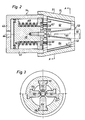
- Fig. 3 den Querschnitt durch das Presswerkzeug längs der Linie A-A in Fig. 2 und
- Fig. 4 ebenfalls in schematischer Darstellung eine bevorzugte Ausführungsform der Verschiebeeinrichtung und des Ausgleichszylinders.
- 1 is a schematic representation of an apparatus for performing the method,
- Fig. 2 shows the longitudinal section through an embodiment of the Press tool of the device according to FIG. 1,
- Fig. 3 shows the cross section through the pressing tool along the line AA in Fig. 2 and
- Fig. 4 also in a schematic representation of a preferred embodiment of the displacement device and the compensating cylinder.
Die in Fig. 1 schematisch gezeigte Vorrichtung enthält ein nicht gezeigtes Maschinenbett, an dem eine Dreheinrichtung 11 und eine Vorschubeinrichtung 12 mit einstellbarem Abstand voneinander befestigbar sind. An der Dreheinrichtung sind auf der der Vorschubeinrichtung zugewandten Seite ein Presswerkzeug 13 und auf der abgewandten Seite eine Presse 14 gehaltert. An der Vorschubeinrichtung 12 ist eine Halteeinrichtung 16 angeordnet. Diese Halteeinrichtung ist zum Halten eines stabförmigen Werkstücks 91 vorgesehen und dazu in der Art eines hydraulisch betätigbaren Mehrbackenfutters ausgebildet.The device shown schematically in FIG. 1 contains a machine bed, not shown, to which a
Die Drehachse der Dreheinrichtung 11, die Symmetrieachse des Presswerkzeugs 13, sowie die Symmetrieachse der Halteeinrichtung 16 liegen ineinander, so dass bei geeignetem Abstand zwischen Presswerkzeug und Halteeinrichtung das Presswerkzeug um ein in der Halteeinrichtung gehaltenes stabförmiges Werkstück gedreht werden kann.The axis of rotation of the
Die Dreheinrichtung 11 und die Presse 14 sowie die Vorschubeinrichtung 12 und die Halteeinrichtung 16 werden hydraulisch betätigt und sind über Hydraulikleitungen 21, 22, 23 bzw. 24 mit einer Hydraulikanlage 17 verbunden. Die Hydrau likanlage enthält eine nicht gezeigte Hydraulikpumpe, die beim Betrieb der Vorrichtung einen konstanten Druck des Hydraulikfluids erzeugt. In jeder Hydraulikleitung ist mindestens ein elektrisch steuerbares Ventil 26, 27, 28 bzw. 29 angeordnet, das über eine elektrische Leitung 31, 32, 33 bzw. 34 mit einer elektronischen Steuerschaltung 36 verbunden ist. Die Hydraulikleitungen 21 und 24 sind zwischen den Ventilen 27 bzw. 29 paarweise ausgeführt, was ermöglicht, die Drehrichtung der Dreheinrichtung 11 umzukehren und die Halteeinrichtung 16 zu schliessen und zu öffnen. Die Leitung 23 zur Vorschubeinrichtung besteht aus mehreren (nicht gezeigten) parallel zueinander verlaufenden Leitungen, von denen jede ein Ventil enthält, das unabhängig von den anderen Ventilen ansteuerbar ist, was mit Hilfe der Fig. 4 noch ausführlich beschrieben werden wird. Die elektronische Steuerschaltung 36 ist für verschiedene Verwendungen der Vorrichtung programmierbar. Weiter ist ein Steuerpult 37 vorgesehen, mit einem Tastenfeld zum Ein- und Ausschalten der Vorrichtung sowie zum Einstellen der Steuerschaltung auf ein ausgewähltes Programm.The
Die Fig. 2 zeigt in einem Längsschnitt ein Presswerkzeug 13 sowie eine zu dessen Betätigung vorgesehene Presse 14. Die Presse 14 enthält einen Hydraulikzylinder 41, in dem ein Kolben 42 in axialer Richtung verschiebbar eingepasst ist. Der Zylinderboden 43 weist eine Bohrung 44 auf, die für den Anschluss der Hydraulikleitung 22 vorgesehen ist. An der der Arbeitsfläche des Kolbens 42 abgewandten Fläche ist eine Kolbenstange 46 angeformt, deren freies Ende durch die zentrale Oeffnung eines ringförmigen Zylinderdeckels 47 aus dem Zylinder herausragt. Am freien Ende der Kolbenstange ist ein Druckstempel 48 befestigt, dessen Durchmesser grösser als der Durchmesser der Kolbenstange ist. Um den im Zylinder liegende Teil der Kolbenstange ist eine Druckfeder 49 gelegt, deren Enden an der rückwärtigen Fläche des Kolbens bzw. an der Innenfläche des Zylinderdeckels anliegen.2 shows a longitudinal section of a
Das Presswerkzeug 13 enthält eine Führungshülse 51, die im Bereich des Zylinderdeckels 47 an der hydraulischen Presse 14 befestigt ist. Die Führungshülse weist einen konischen Innenraum 52 auf, dessen grösster Durchmesser oder Grundkreis dem Druckstempel 48 benachbart ist und dessen kleinster Durchmesser oder Deckkreis eine Oeffnung 53 in der der Presse 14 abgewandten Deckfläche des Presswerkzeuges bildet. In die Wand des konischen Innenraums 52 sind vier um 90° versetzte und im Querschnitt T-förmige Nuten 56, 57, 58, 59 eingearbeitet (Fig. 3). Die Nuten verlaufen parallel zu den Mantellinien des konischen Innenraums und sind darum gegenüber der Längsachse 61 des Presswerkzeugs um einen Winkel α geneigt.The
In den konischen Innenraum sind vier in der Seitenansicht trapezförmige Gewindepressbacken 62, 63, 64, 66 angeordnet. Die Pressbacken weisen einen T-förmigen Querschnitt auf mit einem zweiarmigen Führungsbalken und einem davon abragenden Pressstempel. Jeder Pressbacken ist mit seinem Führungsbalken in einer zugeordneten Nut in der Führungshülse in der Längsrichtung des Presswerkzeugs verschiebbar gelagert und mittels einer Schraube 67, 68 mit dem Druckstempel 48 verbunden. Die Schraubenköpfe sind im Druckstempel in radialen Schlitzen 69, 71 geführt, um die jeder Verschiebung der Pressbacken in axialer Richtung überlagerte Verschiebung in radialer Richtung nicht zu blockieren. Die der Mitte des konischen Innenraums 52 zugewandten Innenflächen der Press backen sind gegenüber der Längsachse 61 um einen Winkel β geneigt. Die Neigungsrichtung dieses Winkels β ist der Neigungsrichtung des Winkels α entgegengesetzt, und der Winkel β ist kleiner als der Winkel α. Die Innenflächen der Pressbacken sind im Querschnitt kreisbogenförmig und weisen ein Oberflächenprofil auf, das einem entsprechenden Teil eines Mutterstücks für das zu pressende konische Aussengewinde entspricht.Four threaded
Die Fig. 4 zeigt eine Vorschubeinrichtung 12, der eine Längenausgleichseinrichtung 71 zugeordnet ist. Die Vorschubeinrichtung enthält ein Gehäuse 72, in das mehrere und im gezeigten Ausführungsbeispiel drei in Serie geschaltete Kolben-Zylinder-Anordnungen eingebaut sind. Die erste Kolben-Zylinder-Anordnung besteht aus einem im Gehäuse fest eingebauten ersten Zylinder 73, an den Druckfluidleitungen 123′ und 123˝ angeschlossen sind. An der Kolbenstange 76 des im ersten Zylinder gleitenden Kolbens 74 ist ein im zweiten Gehäuse 72 verschiebbarer Zylinder 77 befestigt. An diesen zweiten Zylinder sind die Druckfluidleitungen 223′ und 223˝ angeschlossen. An der Kolbenstange 79 des im zweiten Zylinder gleitenden Kolbens 78 ist ein dritter Zylinder 81 befestigt, an den Druckfluidleitungen 323′ und 323˝ angeschlossen sind. Der im dritten Zylinder gleitende Kolben 82 ist mittels einer Kolbenstange 83 mit einem Kolben 84 der Längenausgleichseinrichtung 71 starr verbunden.4 shows a
Der Hub der Kolben in den drei Kolben-Zylinder-Anordnungen ist unterschiedlich lang, was ermöglicht, durch Verschieben eines, zweier oder auch aller drei Kolben den Kolben 84 in der Längenausgleichseinrichtung um vorgegebene Gesamtlängen zu verschieben. Der Arbeitsraum 86 der Längenausgleichsein richtung ist über die Leitung 23A mit der Hydraulikanlage 17 verbunden und wird zu Beginn jedes Arbeitszyklus mit dem Druckfluid gefüllt, so dass bei jeder Verschiebung des Kolbens 84 (in der Fig. 4 nach rechts) der Zylinder 87, der wie die Zylinder der Verschiebeeinrichtung im Gehäuse 72 gleitend angeordnet ist, nach rechts verschoben wird. Der Zylinder 87 ist mit der Halteeinrichtung 16 für das Werkstück direkt oder indirekt mechanisch verbunden, so dass die Halteeinrichtung 16 entsprechend der Verschiebung des Zylinders 87 ebenfalls verschoben wird.The stroke of the pistons in the three piston-cylinder arrangements is of different lengths, which makes it possible to move the
An den Zylinder 87 der Längenausgleichseinrichtung 71 bzw. an die mit diesem Zylinder verbundene Druckfluidleitung 23A ist eine weitere Druckfluidleitung 23B angeschlossen. Diese Leitung enthält ein Ueberdruckventil 88, das öffnet, sobald der Druck im Arbeitsraum 86 einen vorgegebenen Wert übersteigt, wie nachfolgend noch erläutert werden wird.A further pressure fluid line 23B is connected to the
Bei der Verwendung der erfindungsgemässen Vorrichtung zum Kaltpressen eines konischen Gewindes in ein stabförmiges, praktisch zylindrisches Werkstück wird zuerst am Steuerpult 37 die "EIN"- Taste gedrückt, die dann die elektronische Steuerschaltung 36 und die Hydraulikanlage 17 aktiviert. Die Steuerschaltung stellt das Ventil 27 in eine erste Stellung, in der Hydraulikfluid in den Zylinder 41 der Presse 14 einströmt und den Kolben 42 gegen die Kraft der Feder 49 (in der Fig. 2 nach rechts) verschiebt. Dadurch werden auch die Pressbacken 62, 63, 64 und 65 in axialer Richtung verschoben und infolge der Neigung der Führungsnuten 56, 57, 58, 59 gegenüber der Längsachse des Presswerkzeugs zugleich in radialer Richtung zusammengefahren, bis ihre Seitenflächen aneinanderliegen. Gleichzeitig wird auch das Ventil 29 in eine erste Stellung verstellt, in der das einströmende Hydraulikfluid die Haltebacken der Halteeinrichtung 16 in radialer Richtung auseinanderzieht. Dann kann das stabförmige Werkstück 91 in der Richtung des Pfeils 92 zwischen die geöffneten Haltebacken bis zum Anschlag an die zusammengefahrenen Pressbacken eingeführt werden.When using the device according to the invention for cold pressing a conical thread into a rod-shaped, practically cylindrical workpiece, the "ON" button is first pressed on the
Vor dem Beginn des eigentlichen Arbeitszyklus werden mit Hilfe des Tastenfelds am Steuerpult 27 die für den Zyklus wichtigen Kenndaten des Werkstücks in die elektronische Steuerschaltung eingegeben, insbesondere der Durchmesser des Werkstücks, oder der Nenndurchmesser und die Länge des zu pressenden konischen Gewindes und mindestens eine das Material des Werkstücks betreffende Kenngrösse. Die eingegebenen Kennwerte bestimmen dann, welches von mehreren in der Steuerschaltung gespeicherten Arbeitsprogrammen auszuführen ist.Before the start of the actual work cycle, the key data of the workpiece important for the cycle, in particular the diameter of the workpiece, or the nominal diameter and the length of the conical thread to be pressed and at least one the material are entered into the electronic control circuit using the keypad on the control panel 27 characteristic of the workpiece. The entered characteristic values then determine which of several work programs stored in the control circuit is to be carried out.
Der Arbeitszyklus beginnt, sobald am Steuerpult die "START"- Taste gedrückt ist. Beim ersten Arbeitsschritt wird das Ventil 29 in eine zweite Stellung umgesteuert, in der die Haltebacken zusammenfahren, bis das Werkstück festgeklemmt ist. Beim zweiten Arbeitsschritt wird das Ventil 27 in seine zweite Stellung gesteuert, in der der Zylinder 41 der Presse belüftet wird und die Feder 49 den Kolben 42 mitsamt den Pressbacken 62, 63, 64, 66 in die in Fig. 2 gezeigte Ruhestellung zurückzieht. Beim darauffolgenden dritten Arbeitsschritt wird das Ventil 28 in eine erste Stellung gesteuert, in der das durchströmende Hydraulikfluid die Vorschubeinrichtung 12 und damit auch die Halteeinrichtung 16 und das von dieser gehaltene Werkstück 91 um eine vorgegebene Strecke in Richtung des Presswerkzeugs 13 bzw. zwischen die Pressbacken verschiebt. Beim letzten vierten Arbeitsschritt wird das Ventil 27 wieder in seine erste Stellung gesteuert, in der die Pressbacken in axialer Richtung verschoben und zugleich zusammen- und in das Werkstück eingepresst werden, bis ihre Seitenflächen aneinanderliegen.The work cycle begins as soon as the "START" button is pressed on the control panel. In the first step, the
Beim Einpressen der Pressbacken in das Werkstück erzeugt die axiale Komponente von deren Verschiebung einen auf die Halteeinrichtung wirkenden Druck. Dieser Druck wird noch verstärkt, wenn das Material des Werkstücks beim Einpressen der Pressbacken in Richtung des grösseren Werkstückdurchmessers fliesst. Wenn dieser Druck einen vorgegebenen Wert übersteigt, dann öffnet das Ueberdruckventil 88 und ermöglicht eine rückwärts gerichtete Verschiebung des Zylinders 87 mitsamt der daran befestigten Halteeinrichtung, bis der Druck des Werkstücks auf einen tolerierbaren Wert abgesunken ist.When the press jaws are pressed into the workpiece, the axial component of their displacement generates a pressure acting on the holding device. This pressure is increased if the material of the workpiece flows in the direction of the larger workpiece diameter when the press jaws are pressed in. If this pressure exceeds a predetermined value, the
Im nachfolgenden fünften Arbeitsschritt wird das Ventil 27 in die zweite Stellung gesteuert, wodurch die Pressbacken wieder in radialer Richtung auseinandergezogen werden. Beim nächsten sechsten Arbeitsschritt wird das Ventil 26 in die erste Stellung gesteuert, so dass die Dreheinrichtung 11 und mit ihr die Presse 14 und das Presswerkzeug um 45° nach links gedreht werden. Beim siebten Arbeitsschritt wird das Ventil 27 wieder in die erste Stellung gesteuert, wobei die Pressbacken des Presswerkzeugs erneut in radialer Richtung zusammengefahren werden und der Grat, der sich beim Pressen des konischen Gewindes im Bereich der seitlichen Ränder der Pressbacken gebildet hat, ausgepresst wird. Im achten Arbeitsschritt werden durch Ansteuern der Ventile 27 und 26 zuerst die Pressbacken wieder auseinandergezogen und danach das Presswerkzeug um 45° nach rechts in seine Ausgangsstellung gedreht. Das Werkstück mit einem kalt eingepressten ko nischen Gewinde kann dann aus der Vorrichtung entnommen werden.In the subsequent fifth step, the valve 27 is controlled into the second position, whereby the press jaws are pulled apart again in the radial direction. In the next sixth working step, the
Werkstücke mit grossem Durchmesser und/oder aus einem relativ zähen Material bzw. konische Gewinde mit mehr als beispielsweise fünf Gängen werden vorteilhafterweise in mehreren Arbeitszyklen gepresst. Beim zweiten und jedem darauf folgenden Arbeitszyklus bleiben nach dem oben beschriebenen vierten Arbeitsschritt die Pressbacken in der Pressstellung, während in einem ersten Zwischenarbeitsschritt das Ventil 24 in die erste Stellung gesteuert und dadurch die Haltebacken der Halteeinrichtung 16 auseinandergefahren werden. In einem zweiten Zwischenarbeitsschritt wird das Ventil 28 in die zweite Stellung gesteuert und dadurch die Vorschubeinrichtung 12 in ihre Ausgangsstellung zurückgefahren. Anschliessend wird jeder oben beschriebene erste, zweite, dritte und vierte Arbeitsschritt wiederholt, d.h. die Haltebacken werden zusammengefahren, die Pressbacken in die Ruhestellung zurückgezogen, das Werkstück durch Verschieben der Vorschubeinrichtung um eine vorgegebene Länge tiefer in das Presswerkzeug eingeführt und die Pressbacken wieder zusammengepresst.Workpieces with a large diameter and / or made of a relatively tough material or conical thread with more than five gears, for example, are advantageously pressed in several working cycles. In the second and each subsequent working cycle, the pressing jaws remain in the pressing position after the fourth working step described above, while in a first intermediate working step the
Den Abschluss eines Arbeitszyklus bilden immer die oben beschriebenen Arbeitsschritte sechs und sieben, mit denen der beim Pressen des konischen Gewindes unvermeidliche Grat in das Werkstück eingepresst wird.The end of a work cycle is always the work steps six and seven described above, with which the burr that is unavoidable when pressing the conical thread is pressed into the workpiece.
Beim Pressen eines Gewindes in mehreren Arbeitszyklen, wird das Werkstück für jeden Arbeitszyklus tiefer in das Presswerkzeug hineingeschoben. Dabei werden die vorgängig gepressten Gewindegänge nachgepresst und neue Gewindegänge eingepresst. Um die mit zunehmender Anzahl Arbeitszyklen zunehmende, gesamthafte Verformung des Werkstücks im Bereich des Gewindes zu begrenzen, kann es vorteilhaft sein, den Vorschub des Werkstücks in das Presswerkzeug bei jedem nachfolgenden Arbeitszyklus etwas kürzer als beim vorgängigen Arbeitszyklus einzustellen.When pressing a thread in several work cycles, the workpiece is pushed deeper into the press tool for each work cycle. The previously pressed threads are pressed and new threads pressed in. In order to limit the overall deformation of the workpiece in the area of the thread, which increases with an increasing number of working cycles, it can be advantageous to set the feed of the workpiece into the pressing tool somewhat shorter in each subsequent working cycle than in the previous working cycle.
Bei der praktischen Erprobung der erfindungsgemässen Vorrichtung wurden konische Gewinde in Armierungsstähle eingepresst. Jeder Armierungsstahl hatte einen Durchmesser von 40 mm. Das konische Gewinde hatte einen Konus von 6°, eine Steigung von 4 mm und einen Flankenwinkel von 90°, entsprechend einer Gangtiefe von 2 mm oder der halben Steigung Das verwendete Presswerkzeug enthielt vier Pressbacken, von denen jeder in axialer Richtung gesehen einen Querschnitt aufwies, der einem Viertelkreis entsprach. Der Druck der Presse betrug in axialer Richtung bis 650 bar, womit ein Pressdruck der Pressbacken in radialer Richtung von bis 850 t erreicht wurde.In the practical testing of the device according to the invention, conical threads were pressed into reinforcing steels. Each reinforcing steel had a diameter of 40 mm. The conical thread had a cone of 6 °, a pitch of 4 mm and a flank angle of 90 °, corresponding to a pitch of 2 mm or half the pitch. The pressing tool used contained four pressing jaws, each of which had a cross section when viewed in the axial direction, that corresponded to a quarter circle. The pressure of the press was up to 650 bar in the axial direction, whereby a pressing pressure of the press jaws of up to 850 t was achieved in the radial direction.
Zum Kaltpressen eines konischen Gewindes mit 15 Gängen wurden fünf Arbeitszyklen ausgeführt, wobei der Vorschub des Armierungsstahls in das Presswerkzeug beim ersten Zyklus der (axialen) Länge von fünf Gewindegängen und beim zweiten bis fünften Zyklus der Länge von vier, drei, zwei bzw. einem Gewindegang entsprach. Die gesamte Bearbeitungszeit betrug etwa 90 sec. Das fertig gepresste konische Gewinde zeigte weder Ausbrüche noch einen Grat.Five working cycles were carried out for cold-pressing a conical thread with 15 threads, the reinforcing steel being fed into the pressing tool in the first cycle of the (axial) length of five thread turns and in the second to fifth cycle the length of four, three, two or one thread turn corresponded. The total machining time was about 90 seconds. The finished pressed conical thread showed neither chipping nor burr.
Es versteht sich, dass die beschriebene Vorrichtung und deren Einrichtungen auf vielerlei Weise abgeändert und an spezielle Arbeitsbedingungen angepasst werden können. Bei spielsweise kann anstelle einer Presse, die hydraulisch in die Arbeitsstellung und mittels einer Feder in die Ruhestellung verschoben wird, eine Presse verwendet werden, die in beiden Richtungen hydraulisch verschoben wird. Weiter kann eine Vorschubeinrichtung mit nur einem Zylinder verwendet werden, deren Vorschub durch die Menge des eingeleiteten Hydraulikfluids gesteuert wird. Bei einer Vorschubeinrichtung mit nur einem Zylinder kann auch das Ueberdruckventil 88 an diesen Zylinder angeschlossen und dafür auf die Längsausgleichseinrichtung verzichtet werden.It is understood that the described device and its devices can be modified in many ways and adapted to special working conditions. At For example, instead of a press that is moved hydraulically into the working position and into the rest position by means of a spring, a press can be used that is moved hydraulically in both directions. Furthermore, a feed device with only one cylinder can be used, the feed of which is controlled by the amount of hydraulic fluid introduced. In the case of a feed device with only one cylinder, the
Die Vorrichtung kann aus handelsüblichen Bauelementen und -Gruppen zusammengebaut werden, und es wird angenommen, dass auch die elektronische Steuerung und Hydraulikanlage zum Steuern bzw. Betätigen der einzelnen Einrichtungen jedem Fachmann bekannt sind, weshalb auf eine detaillierte Beschreibung dieser Einrichtungen verzichtet wird.The device can be assembled from commercially available components and groups, and it is assumed that the electronic control and hydraulic system for controlling or actuating the individual devices are known to any person skilled in the art, for which reason a detailed description of these devices is dispensed with.
Claims (13)
mit einem Presswerkzeug, das mehrere Pressbacken aufweist, die um eine Längsachse angeordnet und mindestens radial zu dieser verschiebbar sind,
und deren radial innere Flächen einzelnen Segmenten eines Mutterstücks für das zu pressende Gewinde entsprechen, dadurch gekennzeichnet, dass
with a pressing tool which has a plurality of pressing jaws which are arranged about a longitudinal axis and can be displaced at least radially to the latter,
and whose radially inner surfaces correspond to individual segments of a nut piece for the thread to be pressed, characterized in that
eine Halteeinrichtung (16), um das Werkstück (91) in der Längsachse (61) des konischen Innenraums der Führungshülse zu halten,
und eine Vorschubeinrichtung (12), um die Halteeinrichtung und/oder das Presswerkzeug relativ zueinander längs der Achse des konischen Innenraums um einen voreinstellbaren Vorschubweg zu verschieben,
sowie durch eine Dreheinrichtung (11), um die Halteeinrichtung und/oder das Presswerkzeug relativ zueinander um die Achse des konischen Innenraums um einen voreinstellbaren Winkel zu drehen.8. The device for carrying out the method according to claim 1 with a pressing tool (13) with a guide sleeve (51), in the conical interior of which several pressing jaws (62, 63, 64, 66) are mounted displaceably along surface lines of the interior, and with a pressure stamp (48), which is provided for displacing the pressing jaws in the longitudinal direction of the interior, characterized by
a holding device (16) for holding the workpiece (91) in the longitudinal axis (61) of the conical interior of the guide sleeve,
and a feed device (12) for displacing the holding device and / or the pressing tool relative to one another along the axis of the conical interior by a presettable feed path,
and by a rotating device (11) in order to rotate the holding device and / or the pressing tool relative to one another about the axis of the conical inner space by a presettable angle.
Priority Applications (1)
| Application Number | Priority Date | Filing Date | Title |
|---|---|---|---|
| AT89810017T ATE102855T1 (en) | 1988-08-26 | 1989-01-11 | PROCESS FOR COLD PRESSING A TAPERED EXTERNAL THREAD. |
Applications Claiming Priority (2)
| Application Number | Priority Date | Filing Date | Title |
|---|---|---|---|
| CH3190/88 | 1988-08-26 | ||
| CH3190/88A CH676564A5 (en) | 1988-08-26 | 1988-08-26 |
Publications (3)
| Publication Number | Publication Date |
|---|---|
| EP0356375A2 true EP0356375A2 (en) | 1990-02-28 |
| EP0356375A3 EP0356375A3 (en) | 1991-01-16 |
| EP0356375B1 EP0356375B1 (en) | 1994-03-16 |
Family
ID=4250591
Family Applications (1)
| Application Number | Title | Priority Date | Filing Date |
|---|---|---|---|
| EP89810017A Expired - Lifetime EP0356375B1 (en) | 1988-08-26 | 1989-01-11 | Method of cold pressing a conical exterior screw thread |
Country Status (6)
| Country | Link |
|---|---|
| US (1) | US4941341A (en) |
| EP (1) | EP0356375B1 (en) |
| AT (1) | ATE102855T1 (en) |
| CA (1) | CA1318990C (en) |
| CH (1) | CH676564A5 (en) |
| DE (1) | DE58907213D1 (en) |
Cited By (2)
| Publication number | Priority date | Publication date | Assignee | Title |
|---|---|---|---|---|
| DE102007062830A1 (en) | 2007-12-21 | 2009-06-25 | Ifm Electronic Gmbh | Thread manufacturing method for e.g. proximity switch, involves arranging element inside casing so that thread is produced by shaping casing, where element works together with press jaw that surrounds casing |
| DE102008063692A1 (en) | 2007-12-21 | 2009-07-09 | Ifm Electronic Gmbh | Method and device for producing a thread and component and device |
Families Citing this family (2)
| Publication number | Priority date | Publication date | Assignee | Title |
|---|---|---|---|---|
| US5836197A (en) * | 1996-12-16 | 1998-11-17 | Mckee Machine Tool Corp. | Integral machine tool assemblies |
| KR101894848B1 (en) * | 2014-02-28 | 2018-09-05 | 현대자동차주식회사 | Austenitic heat-resistant alloy and method of manufacturing the same |
Citations (5)
| Publication number | Priority date | Publication date | Assignee | Title |
|---|---|---|---|---|
| US2652577A (en) * | 1946-04-27 | 1953-09-22 | Bulloneria E Viteria Italiana | Machine for producing articles from blank stock |
| US3154978A (en) * | 1962-07-09 | 1964-11-03 | United Wire & Supply Corp | Tube pointer |
| US3370451A (en) * | 1965-06-28 | 1968-02-27 | Blaw Knox Co | Apparatus and method for pointing tubes |
| US3417598A (en) * | 1966-08-19 | 1968-12-24 | Manco Mfg Co | Apparatus for pointing work pieces |
| EP0187623A1 (en) * | 1985-01-10 | 1986-07-16 | Urs Kellner | Apparatus for cold-pressing a tapered thread |
Family Cites Families (8)
| Publication number | Priority date | Publication date | Assignee | Title |
|---|---|---|---|---|
| US228033A (en) * | 1880-05-25 | Device for swaging screw-threads on eyebolts | ||
| US408294A (en) * | 1889-08-06 | Swag ing-machine | ||
| US859803A (en) * | 1906-03-28 | 1907-07-09 | Cummings Machine Company | Threaded tube. |
| US1466302A (en) * | 1920-04-26 | 1923-08-28 | Jouve Felix Louis | Machine for swaging or reducing metal |
| US1712108A (en) * | 1926-10-01 | 1929-05-07 | Robert A Goeller | Connecter |
| US2160694A (en) * | 1936-07-09 | 1939-05-30 | Thomas & Betts Corp | Wire connector |
| US2225345A (en) * | 1938-09-17 | 1940-12-17 | Bendix Aviat Corp | Banding press |
| US4751839A (en) * | 1980-05-09 | 1988-06-21 | Ltv Steel Company, Inc. | Method for removing certain of the corrugations in a helically corrugated pipe |
-
1988
- 1988-08-26 CH CH3190/88A patent/CH676564A5/de not_active IP Right Cessation
-
1989
- 1989-01-11 AT AT89810017T patent/ATE102855T1/en not_active IP Right Cessation
- 1989-01-11 EP EP89810017A patent/EP0356375B1/en not_active Expired - Lifetime
- 1989-01-11 DE DE89810017T patent/DE58907213D1/en not_active Expired - Fee Related
- 1989-01-20 CA CA000588799A patent/CA1318990C/en not_active Expired - Fee Related
- 1989-01-23 US US07/300,489 patent/US4941341A/en not_active Expired - Lifetime
Patent Citations (5)
| Publication number | Priority date | Publication date | Assignee | Title |
|---|---|---|---|---|
| US2652577A (en) * | 1946-04-27 | 1953-09-22 | Bulloneria E Viteria Italiana | Machine for producing articles from blank stock |
| US3154978A (en) * | 1962-07-09 | 1964-11-03 | United Wire & Supply Corp | Tube pointer |
| US3370451A (en) * | 1965-06-28 | 1968-02-27 | Blaw Knox Co | Apparatus and method for pointing tubes |
| US3417598A (en) * | 1966-08-19 | 1968-12-24 | Manco Mfg Co | Apparatus for pointing work pieces |
| EP0187623A1 (en) * | 1985-01-10 | 1986-07-16 | Urs Kellner | Apparatus for cold-pressing a tapered thread |
Cited By (3)
| Publication number | Priority date | Publication date | Assignee | Title |
|---|---|---|---|---|
| DE102007062830A1 (en) | 2007-12-21 | 2009-06-25 | Ifm Electronic Gmbh | Thread manufacturing method for e.g. proximity switch, involves arranging element inside casing so that thread is produced by shaping casing, where element works together with press jaw that surrounds casing |
| DE102008063692A1 (en) | 2007-12-21 | 2009-07-09 | Ifm Electronic Gmbh | Method and device for producing a thread and component and device |
| DE102007062830B4 (en) * | 2007-12-21 | 2014-11-27 | Ifm Electronic Gmbh | Method and device for producing a thread and component and device |
Also Published As
| Publication number | Publication date |
|---|---|
| EP0356375B1 (en) | 1994-03-16 |
| EP0356375A3 (en) | 1991-01-16 |
| CH676564A5 (en) | 1991-02-15 |
| CA1318990C (en) | 1993-06-15 |
| US4941341A (en) | 1990-07-17 |
| ATE102855T1 (en) | 1994-04-15 |
| DE58907213D1 (en) | 1994-04-21 |
Similar Documents
| Publication | Publication Date | Title |
|---|---|---|
| EP0187623B1 (en) | Apparatus for cold-pressing a tapered thread | |
| DE69317303T3 (en) | SELF-PUNCHED RIVETS | |
| DE2610467A1 (en) | DEVICE FOR CUTTING PIPES | |
| DE10118664B4 (en) | Clamping device for workpieces to be machined with imbalance compensation | |
| DE3423543A1 (en) | PRESS AND METHOD FOR PRODUCING THE SAME | |
| EP0356375B1 (en) | Method of cold pressing a conical exterior screw thread | |
| DE2165247A1 (en) | DEVICE AND METHOD FOR SEPARATING TUBULAR BLANKS | |
| DE1948119A1 (en) | Device for chamfering the edges of a toothed workpiece | |
| DE29824688U1 (en) | radial press | |
| DE1602064A1 (en) | Process for the production of gradually narrowing rolled profiles and machine for its implementation | |
| DE580175C (en) | Device for clamping the switchable tool or work piece drum with multi-spindle, automatic turning arms | |
| DE4228463C2 (en) | Process for producing an anchor rail for construction technology and device for carrying out the process | |
| WO1999054122A1 (en) | Radial press | |
| DE19611611A1 (en) | Machine press | |
| EP0380739B1 (en) | Method of and device for temporarily clamping workpieces | |
| DE2512654A1 (en) | PIN EXTRACTION DEVICE FOR PILGRIM ROLLING MILLS | |
| DE10251821B3 (en) | Hydraulic time function element for delayed control of hydraulic components has actuating cylinder with piston rod, and rod movement defined precisely due to cylinder construction and volume flow limitation | |
| DE2550216C2 (en) | Device for the continuous extrusion of wire | |
| DE1942673A1 (en) | Method and apparatus for making a finned tube | |
| DE4306396A1 (en) | Device for adjusting the clearance between guide strips and tup | |
| DE962063C (en) | Hydraulic pipe or cable jacket press | |
| DE9315323U1 (en) | Device for producing openings formed from sheet metal housings, in particular switch cabinets | |
| DE598647C (en) | Process for the production of grooves in embossing rollers for lenticular lenticular films | |
| DE2223431A1 (en) | HYDRAULIC CONTROL DEVICE, IN PARTICULAR FOR FORGING PRESSES | |
| DE1807814C (en) | Device for preparing a pipe end for a subsequent drawing process |
Legal Events
| Date | Code | Title | Description |
|---|---|---|---|
| PUAI | Public reference made under article 153(3) epc to a published international application that has entered the european phase |
Free format text: ORIGINAL CODE: 0009012 |
|
| AK | Designated contracting states |
Kind code of ref document: A2 Designated state(s): AT BE DE ES FR GB GR IT LU NL SE |
|
| PUAL | Search report despatched |
Free format text: ORIGINAL CODE: 0009013 |
|
| AK | Designated contracting states |
Kind code of ref document: A3 Designated state(s): AT BE DE ES FR GB GR IT LU NL SE |
|
| 17P | Request for examination filed |
Effective date: 19910406 |
|
| 17Q | First examination report despatched |
Effective date: 19911112 |
|
| RAP1 | Party data changed (applicant data changed or rights of an application transferred) |
Owner name: BBR BAUVERFAHREN AG |
|
| GRAA | (expected) grant |
Free format text: ORIGINAL CODE: 0009210 |
|
| AK | Designated contracting states |
Kind code of ref document: B1 Designated state(s): AT BE DE ES FR GB GR IT LU NL SE |
|
| PG25 | Lapsed in a contracting state [announced via postgrant information from national office to epo] |
Ref country code: GR Free format text: LAPSE BECAUSE OF FAILURE TO SUBMIT A TRANSLATION OF THE DESCRIPTION OR TO PAY THE FEE WITHIN THE PRESCRIBED TIME-LIMIT Effective date: 19940316 Ref country code: ES Free format text: THE PATENT HAS BEEN ANNULLED BY A DECISION OF A NATIONAL AUTHORITY Effective date: 19940316 |
|
| REF | Corresponds to: |
Ref document number: 102855 Country of ref document: AT Date of ref document: 19940415 Kind code of ref document: T |
|
| ITF | It: translation for a ep patent filed | ||
| REF | Corresponds to: |
Ref document number: 58907213 Country of ref document: DE Date of ref document: 19940421 |
|
| GBT | Gb: translation of ep patent filed (gb section 77(6)(a)/1977) |
Effective date: 19940407 |
|
| ET | Fr: translation filed | ||
| PLBE | No opposition filed within time limit |
Free format text: ORIGINAL CODE: 0009261 |
|
| STAA | Information on the status of an ep patent application or granted ep patent |
Free format text: STATUS: NO OPPOSITION FILED WITHIN TIME LIMIT |
|
| EAL | Se: european patent in force in sweden |
Ref document number: 89810017.7 |
|
| PG25 | Lapsed in a contracting state [announced via postgrant information from national office to epo] |
Ref country code: LU Free format text: LAPSE BECAUSE OF NON-PAYMENT OF DUE FEES Effective date: 19950131 |
|
| 26N | No opposition filed | ||
| PG25 | Lapsed in a contracting state [announced via postgrant information from national office to epo] |
Ref country code: NL Effective date: 19950801 |
|
| PG25 | Lapsed in a contracting state [announced via postgrant information from national office to epo] |
Ref country code: FR Effective date: 19950929 |
|
| NLV4 | Nl: lapsed or anulled due to non-payment of the annual fee |
Effective date: 19950801 |
|
| REG | Reference to a national code |
Ref country code: FR Ref legal event code: ST |
|
| PGFP | Annual fee paid to national office [announced via postgrant information from national office to epo] |
Ref country code: BE Payment date: 19981211 Year of fee payment: 11 |
|
| PGFP | Annual fee paid to national office [announced via postgrant information from national office to epo] |
Ref country code: GB Payment date: 19981221 Year of fee payment: 11 |
|
| PGFP | Annual fee paid to national office [announced via postgrant information from national office to epo] |
Ref country code: SE Payment date: 19990114 Year of fee payment: 11 |
|
| PGFP | Annual fee paid to national office [announced via postgrant information from national office to epo] |
Ref country code: AT Payment date: 19990121 Year of fee payment: 11 |
|
| PGFP | Annual fee paid to national office [announced via postgrant information from national office to epo] |
Ref country code: DE Payment date: 19990330 Year of fee payment: 11 |
|
| PG25 | Lapsed in a contracting state [announced via postgrant information from national office to epo] |
Ref country code: GB Free format text: LAPSE BECAUSE OF NON-PAYMENT OF DUE FEES Effective date: 20000111 Ref country code: AT Free format text: LAPSE BECAUSE OF NON-PAYMENT OF DUE FEES Effective date: 20000111 |
|
| PG25 | Lapsed in a contracting state [announced via postgrant information from national office to epo] |
Ref country code: SE Free format text: LAPSE BECAUSE OF NON-PAYMENT OF DUE FEES Effective date: 20000112 |
|
| PG25 | Lapsed in a contracting state [announced via postgrant information from national office to epo] |
Ref country code: BE Free format text: LAPSE BECAUSE OF NON-PAYMENT OF DUE FEES Effective date: 20000131 |
|
| BERE | Be: lapsed |
Owner name: BBR BAUVERFAHREN A.G. Effective date: 20000131 |
|
| GBPC | Gb: european patent ceased through non-payment of renewal fee |
Effective date: 20000111 |
|
| EUG | Se: european patent has lapsed |
Ref document number: 89810017.7 |
|
| PG25 | Lapsed in a contracting state [announced via postgrant information from national office to epo] |
Ref country code: DE Free format text: LAPSE BECAUSE OF NON-PAYMENT OF DUE FEES Effective date: 20001101 |
|
| PG25 | Lapsed in a contracting state [announced via postgrant information from national office to epo] |
Ref country code: IT Free format text: LAPSE BECAUSE OF NON-PAYMENT OF DUE FEES;WARNING: LAPSES OF ITALIAN PATENTS WITH EFFECTIVE DATE BEFORE 2007 MAY HAVE OCCURRED AT ANY TIME BEFORE 2007. THE CORRECT EFFECTIVE DATE MAY BE DIFFERENT FROM THE ONE RECORDED. Effective date: 20050111 |