EP0356245A2 - Werkstoffschneidevorrichtung - Google Patents
Werkstoffschneidevorrichtung Download PDFInfo
- Publication number
- EP0356245A2 EP0356245A2 EP89308630A EP89308630A EP0356245A2 EP 0356245 A2 EP0356245 A2 EP 0356245A2 EP 89308630 A EP89308630 A EP 89308630A EP 89308630 A EP89308630 A EP 89308630A EP 0356245 A2 EP0356245 A2 EP 0356245A2
- Authority
- EP
- European Patent Office
- Prior art keywords
- blade
- cutting
- drive arrangement
- cut
- drive
- Prior art date
- Legal status (The legal status is an assumption and is not a legal conclusion. Google has not performed a legal analysis and makes no representation as to the accuracy of the status listed.)
- Ceased
Links
Images

Classifications
-
- B—PERFORMING OPERATIONS; TRANSPORTING
- B26—HAND CUTTING TOOLS; CUTTING; SEVERING
- B26D—CUTTING; DETAILS COMMON TO MACHINES FOR PERFORATING, PUNCHING, CUTTING-OUT, STAMPING-OUT OR SEVERING
- B26D5/00—Arrangements for operating and controlling machines or devices for cutting, cutting-out, stamping-out, punching, perforating, or severing by means other than cutting
- B26D5/08—Means for actuating the cutting member to effect the cut
- B26D5/086—Electric, magnetic, piezoelectric, electro-magnetic means
-
- B—PERFORMING OPERATIONS; TRANSPORTING
- B26—HAND CUTTING TOOLS; CUTTING; SEVERING
- B26D—CUTTING; DETAILS COMMON TO MACHINES FOR PERFORATING, PUNCHING, CUTTING-OUT, STAMPING-OUT OR SEVERING
- B26D1/00—Cutting through work characterised by the nature or movement of the cutting member or particular materials not otherwise provided for; Apparatus or machines therefor; Cutting members therefor
- B26D1/01—Cutting through work characterised by the nature or movement of the cutting member or particular materials not otherwise provided for; Apparatus or machines therefor; Cutting members therefor involving a cutting member which does not travel with the work
- B26D1/12—Cutting through work characterised by the nature or movement of the cutting member or particular materials not otherwise provided for; Apparatus or machines therefor; Cutting members therefor involving a cutting member which does not travel with the work having a cutting member moving about an axis
- B26D1/25—Cutting through work characterised by the nature or movement of the cutting member or particular materials not otherwise provided for; Apparatus or machines therefor; Cutting members therefor involving a cutting member which does not travel with the work having a cutting member moving about an axis with a non-circular cutting member
- B26D1/26—Cutting through work characterised by the nature or movement of the cutting member or particular materials not otherwise provided for; Apparatus or machines therefor; Cutting members therefor involving a cutting member which does not travel with the work having a cutting member moving about an axis with a non-circular cutting member moving about an axis substantially perpendicular to the line of cut
- B26D1/28—Cutting through work characterised by the nature or movement of the cutting member or particular materials not otherwise provided for; Apparatus or machines therefor; Cutting members therefor involving a cutting member which does not travel with the work having a cutting member moving about an axis with a non-circular cutting member moving about an axis substantially perpendicular to the line of cut and rotating continuously in one direction during cutting
-
- B—PERFORMING OPERATIONS; TRANSPORTING
- B26—HAND CUTTING TOOLS; CUTTING; SEVERING
- B26D—CUTTING; DETAILS COMMON TO MACHINES FOR PERFORATING, PUNCHING, CUTTING-OUT, STAMPING-OUT OR SEVERING
- B26D5/00—Arrangements for operating and controlling machines or devices for cutting, cutting-out, stamping-out, punching, perforating, or severing by means other than cutting
- B26D5/08—Means for actuating the cutting member to effect the cut
Definitions
- This invention relates to material cutting apparatus and more particularly, but not exclusively, to the cutting of plastics material in strip form.
- plastics materials take many forms and, for example, in the case of plastics tubing the physical nature of the tubing can vary over a wide range of factors including, for example, cross section, diameters, flexibility, hardness, resistance to cut and so on.
- the material to be cut can be fed through a pair of aligned guides spaced apart by a distance sufficient to allow the operational passage of the cutter blade through the gap between the guides.
- Stop means can be provided for locating the free end of the material to be cut when cooperating with the guides thereby to set the cut length.
- the conventional arrangement is for the cutter blade to effect a cut once per revolution and for the blade to come to rest between each cutting revolution to provide a dwell time within which the feed of material to attain the next length to be cut is completed.
- the material to be cut can be fed to the cutting zone by a pushing or puller arrangement as may be found convenient.
- optimum cutting performance and quality is related to the rate of cut, that is the angular momentum of the cutter blade. Since the cutter blade is required to be of a relatively light weight and size, e.g., 50 mm. in length, 15mm. deep and some 1,5 mm. in blade thickness the angular cutting velocity needs to be high so as to achieve effective cutting momentum.
- the drive arrangements for the cutter blade are such that the angular velocity (rate of rotation per unit of time) of the blade is arranged to be independent of the number of cutting revolutions of the blade for the same unit of time.
- drive for a cutter blade is derived from a servo-type motor whose output is so controllable as to provide a drive output voltage/time relationship which produces a rapid initial acceleration from rest to a value which produces such angular velocity of the output shaft as to establish a pretermined torque (angular momentum) in the blade sufficient to cause the blade to effect a material cutting stroke and then on completion of a blade cutting stoke a rapid deceleration to bring the output shaft and thus the blade to a rest position.
- the blade is mounted for rotational operation, and the rate of the rotation of the blade is arranged to be greater than the number of cuts effected in the same unit of time.
- the blade is rotationally mounted directly to said output shaft or to said output shaft by way of a drive transmission which can be a fixed ratio drive or a variable ratio drive.
- a drive transmission which can be a fixed ratio drive or a variable ratio drive.
- the relationship between the angular velocity of the blade and the number of cutting strokes for the same unit of time is selectivley adjustable.
- the drive arrangement is so mounted from a support means such that the cutter blade is overhangs means for collecting the cut material.
- guide means are provided for the material to be cut, said guide means including a guide tube, sleeve, channel or the like located both upstream and downstream of the cutter blade whereby the adjacent end regions of the guides define a gap or space through which the blade is able operationally to pass during its cutting operation, the arrangement being such that the material to be cut is supported on both sides of the region of cut.
- the machine shown therein comprises three major sections, a bottom section 1, a central section 2, and a top section 3.
- the bottom section 1 which provides a generally rectangularly shaped housing 4 for control systems and equipment for effecting control and the requisite inter-relating of the operation of the various components of the apparatus.
- the upper surface 5 of the housing 4 presents a flat table like surface.
- the bottom section is mounted upon wheels 6, therebeing bracing means 7 for restraining the apparatus against movement during use.
- the central section 2 as can be seen from the drawings is so shaped as to form, as seen in side view, with the bottom section a generally C-shape formation whereby the upper part 8 of the central section 2 overhangs the top surface 5 of the bottom section 1.
- the central section 5 provides a housing and support for a servo-type electric motor 9 whose output shaft 10 mounts the cutter blade 11 of the apparatus.
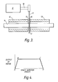
- a pair of guides 12 and 13 for supporting material to be cut is mounted to the structure of the upper part 8 of the central section 2.
- the guides 12 and 13 each comprises a hollow tubular member through the central bore 14 of which the material 15 to be cut is arranged to be fed.
- the guides 12 and 13 are so mounted that the facing ends 16 and 17 thereof are spaced apart to provide a gap 18 through which the cutter blade 11 is able operationally to pass during its cutting operation.
- the control apparatus provided in the bottom section 1 is adapted to produce output control signals which allow control of the operation of the motor such that the output shaft thereof can be caused to rotate according to a predefined angular velocity profile which is represented by the graphical plot of Figure 4.
- control system will enable the setting and adjustment of any parameters considered necessary to the control of effective cutting.
- the profile indicates that the output shaft 10 of the motor 9 is rapidly accelerated from a rest condition (point A) to a cutting velocity (point B) which is maintained for the major part of a blade revolution (from point B to a point C). At the end of this period the output from the motor is reduced to zero as rapidly as possible (that is from point 6 to point D). It will be noted from the profile that a considerable portion, namely from point B to point C, of the rotation period for the shaft is at the required cutting speed whereby the angular momentum of the blade at the time of cutting is as high as possible.
- the rate of rotation for the blade 11 is arranged to be at, for example, a relatively high speed as compared with conventional apparatus for cutting similar materials.
- the rotational speed can be with a range of, for instance, 600 to 1000 revolutions per minute.
- a particular range can be from 750 to 950 with a particular value of, for example, 900.
- control arrangements are arranged to control the motor so that the number of operation cycles per unit time is considerably less than the rate of rotation.
- the number of cycles per unit time can be in the range 300 to 700 with a particular range of 400 to 700.
- the number of cutting cycles can be 500.
- the upper section 4 houses a number of control switches or the like, the switches being exemplified by the switching and operational conditions indicator panel 19.
- the panel 19 can indicate total number of cuts made, can indicate and enable setting of factors such as cutting rates, cutting speeds, cut lengths of materials being cut etc.
- the cutting zone of the apparatus overhangs the bottom section top surface 5. This arrangement makes it possible for cut material collection means, conveyors or the like to be conveniently located below the cutting zone.
Landscapes
- Life Sciences & Earth Sciences (AREA)
- Forests & Forestry (AREA)
- Engineering & Computer Science (AREA)
- Mechanical Engineering (AREA)
- Sawing (AREA)
Applications Claiming Priority (2)
| Application Number | Priority Date | Filing Date | Title |
|---|---|---|---|
| GB8820301 | 1988-08-26 | ||
| GB888820301A GB8820301D0 (en) | 1988-08-26 | 1988-08-26 | Material cutting apparatus |
Publications (2)
| Publication Number | Publication Date |
|---|---|
| EP0356245A2 true EP0356245A2 (de) | 1990-02-28 |
| EP0356245A3 EP0356245A3 (de) | 1991-07-24 |
Family
ID=10642768
Family Applications (1)
| Application Number | Title | Priority Date | Filing Date |
|---|---|---|---|
| EP19890308630 Ceased EP0356245A3 (de) | 1988-08-26 | 1989-08-24 | Werkstoffschneidevorrichtung |
Country Status (2)
| Country | Link |
|---|---|
| EP (1) | EP0356245A3 (de) |
| GB (2) | GB8820301D0 (de) |
Cited By (2)
| Publication number | Priority date | Publication date | Assignee | Title |
|---|---|---|---|---|
| CN112140188A (zh) * | 2020-09-22 | 2020-12-29 | 安徽国康体育用品有限公司 | 一种活塞式乒乓球拍胶皮割边装置 |
| CN113447296A (zh) * | 2021-06-24 | 2021-09-28 | 浙江大学 | 一种适用于椭球形水果的智能定量取样装置 |
Families Citing this family (2)
| Publication number | Priority date | Publication date | Assignee | Title |
|---|---|---|---|---|
| CN105665835A (zh) * | 2016-03-29 | 2016-06-15 | 苏州市合叶精密机械有限公司 | 切割机床 |
| CN105665836A (zh) * | 2016-03-29 | 2016-06-15 | 苏州市合叶精密机械有限公司 | 适用范围广的切割机床 |
Family Cites Families (7)
| Publication number | Priority date | Publication date | Assignee | Title |
|---|---|---|---|---|
| US3114282A (en) * | 1958-04-05 | 1963-12-17 | Reifenhauser K G | Apparatus for the transverse severance of continuously moving tubular structures |
| GB926188A (en) * | 1959-11-17 | 1963-05-15 | Preformed Line Products Co | Wire cutting mechanism |
| GB1386596A (en) * | 1971-05-27 | 1975-03-12 | Squire Ltd Frederick | Cutting apparatus |
| US4043238A (en) * | 1976-04-21 | 1977-08-23 | Sanders Associates, Inc. | Cable cutter |
| SE406289B (sv) * | 1976-11-17 | 1979-02-05 | Morling C H V | Anordning for avkapning av foretredesvis av strengsprutad plast bestaende stang- eller rorformigt gods |
| DE2748820C3 (de) * | 1977-10-31 | 1981-08-06 | Windmöller & Hölscher, 4540 Lengerich | Vorrichtung zum Quertrennen oder Querperforieren von Materialbahnen |
| US4503006A (en) * | 1982-07-28 | 1985-03-05 | Toska Co., Ltd. | Method and apparatus for manufacturing tag pin assemblies |
-
1988
- 1988-08-26 GB GB888820301A patent/GB8820301D0/en active Pending
-
1989
- 1989-08-24 EP EP19890308630 patent/EP0356245A3/de not_active Ceased
- 1989-08-25 GB GB8919353A patent/GB2245210B/en not_active Expired - Fee Related
Cited By (2)
| Publication number | Priority date | Publication date | Assignee | Title |
|---|---|---|---|---|
| CN112140188A (zh) * | 2020-09-22 | 2020-12-29 | 安徽国康体育用品有限公司 | 一种活塞式乒乓球拍胶皮割边装置 |
| CN113447296A (zh) * | 2021-06-24 | 2021-09-28 | 浙江大学 | 一种适用于椭球形水果的智能定量取样装置 |
Also Published As
| Publication number | Publication date |
|---|---|
| EP0356245A3 (de) | 1991-07-24 |
| GB2245210A (en) | 1992-01-02 |
| GB8919353D0 (en) | 1989-10-11 |
| GB8820301D0 (en) | 1988-09-28 |
| GB2245210B (en) | 1993-04-28 |
Similar Documents
| Publication | Publication Date | Title |
|---|---|---|
| EP0248354B1 (de) | Aufschnitt-Schneidemaschine | |
| US4292867A (en) | Apparatus and method for slitting elongated rolls of material | |
| CA1092964A (en) | Rotary web shearing machine | |
| CN202622857U (zh) | 塑料管材旋切装置 | |
| US3869948A (en) | Shear apparatus | |
| CN109202993B (zh) | 一种橡胶棒自动切割设备及橡胶棒自动切割工艺 | |
| US4614138A (en) | Cutter for plaster board and the like | |
| EP0107971A1 (de) | Kantenschneider und Schrottzerkleinerungseinrichtung | |
| EP0356245A2 (de) | Werkstoffschneidevorrichtung | |
| CN210439043U (zh) | 用于化纤布生产的截断器 | |
| CA1072004A (en) | Rotary shear machine | |
| CN216227178U (zh) | 一种防火风管加工用剪板机 | |
| US2839871A (en) | Glass rod and tube cutting mechanism | |
| DE2622584C3 (de) | Vorrichtung zum Kalttrennen von langgestrecktem, ruhendem oder bewegtem Schnittgut | |
| CN216421259U (zh) | 一种具有定位防护功能的剪板机 | |
| CN217727290U (zh) | 一种带锯条裁切装置 | |
| US3350967A (en) | Slitting mechanism | |
| US2619130A (en) | Gang ripsaw | |
| CN210998960U (zh) | 一种x方向的裁切装置 | |
| US3068732A (en) | Flying cutter carriage having mechanical means to vary the instantaneous angular speed of the cutter carriage drive shaft | |
| CN223115319U (zh) | 一种尼龙膜分切加工装置 | |
| JPS6021125Y2 (ja) | フライイングカツタ−装置 | |
| JP2825539B2 (ja) | 連続ガラス管の切断方法および切断装置 | |
| CN223339565U (zh) | 一种中药材切片机 | |
| CN219169731U (zh) | 一种便于固定工件的剪板机 |
Legal Events
| Date | Code | Title | Description |
|---|---|---|---|
| PUAI | Public reference made under article 153(3) epc to a published international application that has entered the european phase |
Free format text: ORIGINAL CODE: 0009012 |
|
| AK | Designated contracting states |
Kind code of ref document: A2 Designated state(s): AT BE CH DE ES FR GB GR IT LI LU NL SE |
|
| RBV | Designated contracting states (corrected) |
Designated state(s): DE ES FR IT |
|
| PUAL | Search report despatched |
Free format text: ORIGINAL CODE: 0009013 |
|
| AK | Designated contracting states |
Kind code of ref document: A3 Designated state(s): AT BE CH DE ES FR GB GR IT LI LU NL SE |
|
| 17P | Request for examination filed |
Effective date: 19920124 |
|
| 17Q | First examination report despatched |
Effective date: 19930728 |
|
| STAA | Information on the status of an ep patent application or granted ep patent |
Free format text: STATUS: THE APPLICATION HAS BEEN REFUSED |
|
| 18R | Application refused |
Effective date: 19950623 |