EP0356004A2 - Kraftwagensitzaufbau und Verfahren zu dessen Einbau - Google Patents
Kraftwagensitzaufbau und Verfahren zu dessen Einbau Download PDFInfo
- Publication number
- EP0356004A2 EP0356004A2 EP89307487A EP89307487A EP0356004A2 EP 0356004 A2 EP0356004 A2 EP 0356004A2 EP 89307487 A EP89307487 A EP 89307487A EP 89307487 A EP89307487 A EP 89307487A EP 0356004 A2 EP0356004 A2 EP 0356004A2
- Authority
- EP
- European Patent Office
- Prior art keywords
- seat
- cushion
- frame
- support frame
- seat assembly
- Prior art date
- Legal status (The legal status is an assumption and is not a legal conclusion. Google has not performed a legal analysis and makes no representation as to the accuracy of the status listed.)
- Withdrawn
Links
Images



Classifications
-
- B—PERFORMING OPERATIONS; TRANSPORTING
- B60—VEHICLES IN GENERAL
- B60N—SEATS SPECIALLY ADAPTED FOR VEHICLES; VEHICLE PASSENGER ACCOMMODATION NOT OTHERWISE PROVIDED FOR
- B60N2/00—Seats specially adapted for vehicles; Arrangement or mounting of seats in vehicles
- B60N2/005—Arrangement or mounting of seats in vehicles, e.g. dismountable auxiliary seats
- B60N2/015—Attaching seats directly to vehicle chassis
-
- B—PERFORMING OPERATIONS; TRANSPORTING
- B60—VEHICLES IN GENERAL
- B60N—SEATS SPECIALLY ADAPTED FOR VEHICLES; VEHICLE PASSENGER ACCOMMODATION NOT OTHERWISE PROVIDED FOR
- B60N2/00—Seats specially adapted for vehicles; Arrangement or mounting of seats in vehicles
Definitions
- This invention relates to automotive seat assemblies and in particular to a seat assembly in which the labor required to install the seat into a motor vehicle is reduced.
- One method of reducing the labor cost is to automate the assembly process by using robotics.
- One problem with the use of robots is manipulating the robot into small spaces required for some assembly operations.
- An example of a difficult operation for robots to perform is attaching a seat assembly to the vehicle floor plan. The difficulty lies not in the operation itself but in the limited space between the seat cushion and the floor pan in which the robot must perform the operation. By providing greater access to the seat frame and floor pan, this operation can easily be automated.
- the seat assembly of this invention comprises three major components: 1) a support frame which is attached to the vehicle floor pan; 2) a seat back extending generally vertically from the rear of the support frame; and 3) a seat cushion which, in its operative position, is supported by and on the support frame in a generally horizontal position forward of the seat back.
- the seat cushion is movably mounted to the support frame at the rear of the seat cushion.
- the cushion is in an upright position in which the cushion is extending upward generally parallel to and immediately in front of the seat back. In this position, the support frame is accessible from above, allowing the support frame to be easily attached to the vehicle.
- a second robot can be used to attach the support frame to the floor pan by welding, riveting, bolting or the like.
- the seat cushion is then moved downward into its operative position extending generally horizontally forward of the seat back and supported on the support frame.
- An attaching structure provided on the seat cushion and the support frame which is engagable upon downward movement of the seat cushion onto the support frame, holds the seat cushion in place upon the support frame.
- a seat assembly 10 is illustrated in Figure 1 being positioned into a vehicle body 12 through a door opening 14, the door assembly for the door opening 14 having not yet been installed on the vehicle body 12.
- the seat assembly 10 includes a support frame 16 which is to be attached to the floor pan 13 of the vehicle body 12.
- the support frame 16 is equipped with a conventional seat position adjusting mechanism having a lever 18 for actuation of the adjusting mechanism latch.
- Extending upward from the rear of the support frame 16 is a seat back assembly 20.
- the seat back assembly 20 includes a frame which is attached to the rear end of the support frame 16 in a conventional manner.
- Seat back 20 may be equipped with a reclining means for adjusting the vertical inclination of the seat back assembly.
- the seat cushion 22 of seat assembly 10 is in a position extending vertically upward from the rear portion of the support frame.
- the seat cushion 22 includes a seat cushion frame 24.
- the rear end of the seat cushion frame 24 is pivotally attached to the support frame 16.
- the seat cushion 22 further includes a foam body 23 which partially encapsulates the seat cushion frame 24, and which is then covered by a seat cover upholstery 28.
- a robot arm 32 is shown moving the seat assembly 10 into the interior of the vehicle body 12.
- the robot arm 32 is equipped with a tool 34 which is adapted to grasp the support frame 16 of the seat assembly for transporting the seat assembly.
- the support frame 16 includes a plurality of mounting flanges 36 which are used for securing the support frame 16 to mounting bases 38 on the vehicle body floor pan.
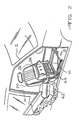
- Figure 2 illustrates the seat assembly 10 in position on the floor pan 13 of vehicle body 12.
- a second robot arm 42 is equipped with a tool 44 which is used to attach the support frame 16 to the floor pan.
- the support frame can be attached in one of several methods such as welding, bolting, riveting and the like.
- the seat cushion assembly 22 is pivoted downward about its rearward end, as shown by arrows 25, from the installation position shown in phantom lines to its operative position extending generally horizontally from the seat back and secured to the support frame 16.
- the attachment of the seat cushion frame 24 to support frame 16 is illustrated in greater detail in Figures 4 and 5.
- FIG. 4 shows the seat cushion 22 and supporting frame 16. A portion of the upholstery and foam padding of the seat cushion is cut away to show details of the seat cushion frame 24.
- Seat cushion frame 24 includes a side rail member 38 which is hinged at its rearward end to a frame rail 40 of the support frame 16.
- a pin 46 pivotally connects the side rail 38 to the frame rail 40.
- Frame rail 40 is slidable mounted within floor mounting rail 41 to allow adjustment of the seat position.
- the frame rail 40 includes an upward extending vertical portion 48 having a bend 50 which divides the vertical portion into a lower vertical section 52 and an upper vertical section 54. Sections 54 and 52 lie in parallel planes with the plane of upper section 54 spaced laterally outwardly relative to the center of the seat from the plane of vertical section 52.
- a slotted aperture 56 is formed in the bend 50 near the forward end of frame rail 40.
- the side rail 38 of seat cushion frame 24 includes a downwardly extending vertical member 39. Projecting downwardly from member 39 is a locking flange 58 which is bent laterally outwardly from vertical member 39 into a plane parallel to member 39. When the seat cushion assembly 22 is pivoted downward about its rearward end, the locking flange 58 projects through the aperture 56 such that the flange 58 is laterally outwardly of the vertical section 52 of the frame rail 40.
- the vertical member 39 is laterally inwardly of the upper vertical section 54 of frame rail 40.
- Figure 5 is a cross section of the seat cushion and support frame in the region of the aperture 56.
- the mechanism for locking the seat cushion frame to the support frame 16 need not be limited to the construction shown in Figures 4 and 5.
- Other latching mechanisms which are engagable upon downward motion of the seat cushion to the support frame can be utilized.
- the seat cushion does not need to be pivotally attached to the support frame at the rear of the seat cushion.
- the seat cushion can be attached to the support frame in any manner which allows movement of the cushion from an installation position providing access to the support frame from above to an operable position upon the support frame.
- the seat cushion can be provided as a separate component which is installed by lowering the seat cushion onto the support frame after the support frame is attached to the floor pan. In this case, the cushion and support frame would have attaching means at both the front and rear ends.
- the means for attaching the cushion to the frame should be operable in response to the motion of the seat cushion into the operative position.
- the seat assembly of this invention lends itself to ease of assembly into the vehicle body.
- the support frame is accessible for first grasping by a robot arm to transport the seat assembly into the vehicle body and secondly for attaching the support frame to the floor pan.
- This seat assembly lends itself easily to automated assembly by use of robots.
Landscapes
- Engineering & Computer Science (AREA)
- Aviation & Aerospace Engineering (AREA)
- Transportation (AREA)
- Mechanical Engineering (AREA)
- Seats For Vehicles (AREA)
- Automobile Manufacture Line, Endless Track Vehicle, Trailer (AREA)
Applications Claiming Priority (2)
| Application Number | Priority Date | Filing Date | Title |
|---|---|---|---|
| US23373388A | 1988-08-19 | 1988-08-19 | |
| US233733 | 2002-09-03 |
Publications (2)
| Publication Number | Publication Date |
|---|---|
| EP0356004A2 true EP0356004A2 (de) | 1990-02-28 |
| EP0356004A3 EP0356004A3 (de) | 1991-05-15 |
Family
ID=22878480
Family Applications (1)
| Application Number | Title | Priority Date | Filing Date |
|---|---|---|---|
| EP19890307487 Withdrawn EP0356004A3 (de) | 1988-08-19 | 1989-07-24 | Kraftwagensitzaufbau und Verfahren zu dessen Einbau |
Country Status (3)
| Country | Link |
|---|---|
| EP (1) | EP0356004A3 (de) |
| JP (1) | JPH0299433A (de) |
| KR (1) | KR900002991A (de) |
Cited By (2)
| Publication number | Priority date | Publication date | Assignee | Title |
|---|---|---|---|---|
| US5527080A (en) * | 1993-06-11 | 1996-06-18 | Scania Cv Aktiebolag | Arrangement and process for fastening a seat to a seat base in a vehicle |
| WO2013132178A1 (fr) * | 2012-03-09 | 2013-09-12 | Peugeot Citroen Automobiles Sa | Dispositif de mise en place d'un siege ou d'un ensemble de sieges de meme rang dans un vehicule, et procede associe |
Family Cites Families (3)
| Publication number | Priority date | Publication date | Assignee | Title |
|---|---|---|---|---|
| DE2841232A1 (de) * | 1978-09-22 | 1980-04-03 | Trepel Ag | Stuhlwagen |
| FR2563716B1 (fr) * | 1984-05-07 | 1987-06-19 | Renault | Siege repliable avec dispositifs de verrouillage du dossier et de l'assise |
| FR2593440B1 (fr) * | 1986-01-27 | 1988-05-06 | Peugeot Cycles | Armature de siege de vehicule automobile ou analogue |
-
1989
- 1989-07-24 EP EP19890307487 patent/EP0356004A3/de not_active Withdrawn
- 1989-08-16 JP JP1211221A patent/JPH0299433A/ja active Pending
- 1989-08-18 KR KR1019890011793A patent/KR900002991A/ko not_active Withdrawn
Cited By (3)
| Publication number | Priority date | Publication date | Assignee | Title |
|---|---|---|---|---|
| US5527080A (en) * | 1993-06-11 | 1996-06-18 | Scania Cv Aktiebolag | Arrangement and process for fastening a seat to a seat base in a vehicle |
| WO2013132178A1 (fr) * | 2012-03-09 | 2013-09-12 | Peugeot Citroen Automobiles Sa | Dispositif de mise en place d'un siege ou d'un ensemble de sieges de meme rang dans un vehicule, et procede associe |
| FR2987810A1 (fr) * | 2012-03-09 | 2013-09-13 | Peugeot Citroen Automobiles Sa | Dispositif de mise en place d'un siege ou d'un ensemble de sieges de meme rang dans un vehicule, et procede associe. |
Also Published As
| Publication number | Publication date |
|---|---|
| JPH0299433A (ja) | 1990-04-11 |
| KR900002991A (ko) | 1990-03-23 |
| EP0356004A3 (de) | 1991-05-15 |
Similar Documents
| Publication | Publication Date | Title |
|---|---|---|
| US5707103A (en) | Storable and removable seat assembly | |
| US6199252B1 (en) | Modular seat assembly and method of installing the same within a vehicle | |
| EP1680295B1 (de) | Rahmen für unten angeschlagene heckklappe | |
| US5443239A (en) | Seat support for a motor vehicle | |
| US6823628B2 (en) | Modular vehicle door assembly | |
| US4065178A (en) | Easy enter seat assembly | |
| EP0712746A1 (de) | Modul für Kraftfahrzeugtür | |
| US20110037289A1 (en) | Door trim panel having temporary support and pivot members and method of installing the door trim panel | |
| JPH06183261A (ja) | 車両用ドアの構造及び組立方法 | |
| JPH0840117A (ja) | 乗物用三列シート組立体 | |
| US11060326B2 (en) | Door latch assemblies for vehicles including latch release lever blocking structures | |
| JPH02225130A (ja) | 自動車のサンルーフ構造 | |
| US20240367729A1 (en) | Tailgate subassembly presetting method and tailgate assembly having preset subassemblies | |
| US6145910A (en) | Method of installing a vehicle interior | |
| EP0561518A1 (de) | Sitzaufbau mit integrierten Sitzkissen und Gleitschienengestell | |
| CA1288455C (en) | Vehicle compartment closure arrangement | |
| US4046349A (en) | Support assembly for forwardly shiftable vehicle seat | |
| EP0356004A2 (de) | Kraftwagensitzaufbau und Verfahren zu dessen Einbau | |
| KR100348449B1 (ko) | 오버헤드형 차량용 공조유니트의 부착구조 및 부착방법 | |
| EP0336636A2 (de) | Funktionaler Türaufbau und dessen Fabrikationsverfahren | |
| CN110626235B (zh) | 用于车辆座椅底部的紧固装置 | |
| JPH0528099Y2 (de) | ||
| JP2821021B2 (ja) | 自動車用ドア | |
| JP3538821B2 (ja) | 車両ドアの取り付け方法および装置 | |
| JPH07112637A (ja) | 車両用シート支持装置 |
Legal Events
| Date | Code | Title | Description |
|---|---|---|---|
| PUAI | Public reference made under article 153(3) epc to a published international application that has entered the european phase |
Free format text: ORIGINAL CODE: 0009012 |
|
| AK | Designated contracting states |
Kind code of ref document: A2 Designated state(s): BE DE ES FR GB IT |
|
| PUAL | Search report despatched |
Free format text: ORIGINAL CODE: 0009013 |
|
| AK | Designated contracting states |
Kind code of ref document: A3 Designated state(s): BE DE ES FR GB IT |
|
| STAA | Information on the status of an ep patent application or granted ep patent |
Free format text: STATUS: THE APPLICATION IS DEEMED TO BE WITHDRAWN |
|
| 18D | Application deemed to be withdrawn |
Effective date: 19910926 |