EP0354797A2 - Dispositif de dégazéification - Google Patents
Dispositif de dégazéification Download PDFInfo
- Publication number
- EP0354797A2 EP0354797A2 EP89308163A EP89308163A EP0354797A2 EP 0354797 A2 EP0354797 A2 EP 0354797A2 EP 89308163 A EP89308163 A EP 89308163A EP 89308163 A EP89308163 A EP 89308163A EP 0354797 A2 EP0354797 A2 EP 0354797A2
- Authority
- EP
- European Patent Office
- Prior art keywords
- film material
- spacer means
- liquid
- degassing device
- degassing
- Prior art date
- Legal status (The legal status is an assumption and is not a legal conclusion. Google has not performed a legal analysis and makes no representation as to the accuracy of the status listed.)
- Withdrawn
Links
- 238000007872 degassing Methods 0.000 title claims abstract description 34
- 239000000463 material Substances 0.000 claims abstract description 45
- 239000007788 liquid Substances 0.000 claims abstract description 40
- 125000006850 spacer group Chemical group 0.000 claims abstract description 29
- -1 polypropylene Polymers 0.000 claims description 9
- 229920001343 polytetrafluoroethylene Polymers 0.000 claims description 7
- 239000004810 polytetrafluoroethylene Substances 0.000 claims description 7
- 239000004745 nonwoven fabric Substances 0.000 claims description 3
- 239000004743 Polypropylene Substances 0.000 claims description 2
- 229920001155 polypropylene Polymers 0.000 claims description 2
- 229920000915 polyvinyl chloride Polymers 0.000 claims description 2
- 239000004800 polyvinyl chloride Substances 0.000 claims description 2
- 238000004804 winding Methods 0.000 claims 1
- 239000007789 gas Substances 0.000 description 19
- 238000000034 method Methods 0.000 description 12
- QVGXLLKOCUKJST-UHFFFAOYSA-N atomic oxygen Chemical compound [O] QVGXLLKOCUKJST-UHFFFAOYSA-N 0.000 description 5
- 238000004519 manufacturing process Methods 0.000 description 5
- 239000001301 oxygen Substances 0.000 description 5
- 229910052760 oxygen Inorganic materials 0.000 description 5
- 238000000926 separation method Methods 0.000 description 5
- 239000012528 membrane Substances 0.000 description 4
- XLYOFNOQVPJJNP-UHFFFAOYSA-N water Substances O XLYOFNOQVPJJNP-UHFFFAOYSA-N 0.000 description 4
- 238000009434 installation Methods 0.000 description 3
- 102100026827 Protein associated with UVRAG as autophagy enhancer Human genes 0.000 description 1
- 101710102978 Protein associated with UVRAG as autophagy enhancer Proteins 0.000 description 1
- 238000005452 bending Methods 0.000 description 1
- 238000010276 construction Methods 0.000 description 1
- 230000007797 corrosion Effects 0.000 description 1
- 238000005260 corrosion Methods 0.000 description 1
- 230000002939 deleterious effect Effects 0.000 description 1
- 238000010586 diagram Methods 0.000 description 1
- 238000009792 diffusion process Methods 0.000 description 1
- 230000000694 effects Effects 0.000 description 1
- 239000004744 fabric Substances 0.000 description 1
- 238000010438 heat treatment Methods 0.000 description 1
- 238000010030 laminating Methods 0.000 description 1
- 230000003647 oxidation Effects 0.000 description 1
- 238000007254 oxidation reaction Methods 0.000 description 1
- 239000011148 porous material Substances 0.000 description 1
- 230000001737 promoting effect Effects 0.000 description 1
- 239000002994 raw material Substances 0.000 description 1
- 230000003014 reinforcing effect Effects 0.000 description 1
- 239000012779 reinforcing material Substances 0.000 description 1
- 239000005871 repellent Substances 0.000 description 1
- 229920005989 resin Polymers 0.000 description 1
- 239000011347 resin Substances 0.000 description 1
- 239000004065 semiconductor Substances 0.000 description 1
- 229920003002 synthetic resin Polymers 0.000 description 1
- 239000000057 synthetic resin Substances 0.000 description 1
- 239000008399 tap water Substances 0.000 description 1
- 235000020679 tap water Nutrition 0.000 description 1
Images

Classifications
-
- B—PERFORMING OPERATIONS; TRANSPORTING
- B01—PHYSICAL OR CHEMICAL PROCESSES OR APPARATUS IN GENERAL
- B01D—SEPARATION
- B01D63/00—Apparatus in general for separation processes using semi-permeable membranes
- B01D63/10—Spiral-wound membrane modules
- B01D63/101—Spiral winding
-
- B—PERFORMING OPERATIONS; TRANSPORTING
- B01—PHYSICAL OR CHEMICAL PROCESSES OR APPARATUS IN GENERAL
- B01D—SEPARATION
- B01D19/00—Degasification of liquids
- B01D19/0031—Degasification of liquids by filtration
-
- B—PERFORMING OPERATIONS; TRANSPORTING
- B01—PHYSICAL OR CHEMICAL PROCESSES OR APPARATUS IN GENERAL
- B01D—SEPARATION
- B01D61/00—Processes of separation using semi-permeable membranes, e.g. dialysis, osmosis or ultrafiltration; Apparatus, accessories or auxiliary operations specially adapted therefor
-
- B—PERFORMING OPERATIONS; TRANSPORTING
- B01—PHYSICAL OR CHEMICAL PROCESSES OR APPARATUS IN GENERAL
- B01D—SEPARATION
- B01D63/00—Apparatus in general for separation processes using semi-permeable membranes
- B01D63/10—Spiral-wound membrane modules
Definitions
- the present invention relates to a device for the separation and removal of gas from gas-containing liquids.
- a device for the separation and removal of gas from gas-containing liquids.
- Such a device may be used, for example, for (a) preventing rusting or corrosion of pipework caused by solute gases in heating and hot water supply systems in buildings, etc., (b) preventing oxidation of liquid foodstuffs or pure water (used in the food industry) caused by solute oxygen, and (c) removing undesirable solute gases from pure water used in semiconductor manufacture, etc.
- Degassing columns suffer from the drawback that a large apparatus with a height of 3 to 4 metres is required even in cases where the amount of liquid to be treated is relatively small. In cases where this amount of space is not available, a batch type system must be used. In the case of methods using gas-permeable membranes, the apparatus used can be made more compact than is possible in the case of conventional degassing column methods, but efficient separation is still not achieved.
- the liquid may be passed through the interior of the tube, and the gaseous components removed from the outside of the tube under reduced pressure.
- the tube must be long and slender or extremely thin in order to obtain a high degassing efficiency.
- the pressure loss is large so that it is difficult to pass high-viscosity liquids through the apparatus.
- the need for pumps increases the size of the apparatus.
- a degassing device comprising a liquid impermeable gas permeable film material and spacer means which are disposed alternately in spiral coils within a housing, the spacer means on one side of the film material defining a liquid flow path, and the pacer means on the other side of the film material defining a passage for gas removed from the liquid.
- the construction of the degassing device in accordance with the invention (a) improves the efficiency of the mechanism used to separate and remove gaseous components from gas-containing liquids, (b) enables effective degassing to be achieved by means of a compact mechanism, and (c) provides a degassing mechanism which allows the appropriate use of a low-cost treatment even in the case of high-viscosity liquids.
- liquid-impermeable gas-permeable film material and the spacer means are alternately positioned in spiral coils and set inside the housing, an installation relationship is obtained in which the film material and spacer means are effectively formed into an integral unit, and in which a fixed spacing is maintained. As a result, a gas-separating mechanism is formed which utilizes the entire surface of the film material.
- the spacer means is positioned on both sides of the film material (which is a continuously porous film) so that a sandwich-type arrangement is formed. As a result, a liquid flow path is formed on one side of the film material, while a passage for separated gas is formed on the other side of the film material. Because of the spiral-coil installation inside a housing, the film material and spacer means form the desired degassing mechanism using a minimum of unit elements. This facilitates manufacture and assembly, reduces the size of the apparatus, and reduces costs.
- the entire space inside the housing is utilized for the degassing treatment.
- the film material (1) used in the degassing device shown in Figure 1 is a synthetic resin film with a continuously porous structure, and may be a polytetrafluoroethylene film obtained by drawing to a pore size of 2 microns or less and a porosity of approximately 5 to 95%.
- a film is permeable to gases as a result of its porous structure, but at the same time is effectively impermeable to liquids as a result of the fineness of the aforementioned porous structure and the water-repellent nature of the material itself.
- the gas-permeable liquid-impermeable film material (1) and a netform spacer (2) are mounted together, and the assembly consisting of these two parts (1) and (2) is wound in the form of a spiral coil and installed inside a housing (8) so that a fixed spacing (3,3a) is maintained on opposite sides of the film material (1).
- a net-like material or non-woven fabric made of polypropylene, polyvinyl chloride or polytetrafluoroethylene, etc. may be used for the spacer (2).
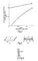
- the film material (1) and the spacer (2) are assembled by the method illustrated in Figure 3. Specifically, a continuous loop (10) is formed with the film material (1), and spacers (2,2) are installed both inside and outside said loop.
- a liquid supply port (4), a liquid discharge port (5) and gas discharge ports (6,6), each comprising a pipe formed with longitudinally oriented holes (7) in its wall as shown in Figure 4, are installed at the ends of this assembly and the assembly is then rolled up in the form of a spiral and inserted into a cylindrical housing (8) as shown in Figure 1.
- the thick layers both consist of the spacer material (2), the film material (1) being indicated by the solid line separating the thick layers.
- the liquid supply port (4) is installed at one end of one of the spaces (3a) formed by the spacers (2) as described above, while the liquid discharge port (5) is installed at the other end of said space (3a).
- the gas discharge ports (6,6) which are connected to a vacuum pump and a vacuum tank, are respectively installed at opposite ends of the space (3) (in positions along a radial line) on the other side of the film material (1) from the space (3a).
- the space (3) is placed under reduced pressure.
- the top of the housing (8) is sealed by means of a closure device, such as a lid.
- any reinforcing material with a net-form structure or other porous structure may be used for the spacers (2).
- a material which has a complicated surface form and a structure that tends to generate turbulent flow in the liquid it is desirable to use a material which has a complicated surface form and a structure that tends to generate turbulent flow in the liquid. It is advantageous if the thickness of said spacer material is small; for example, a material such as a non-woven fabric (installed on one or both surfaces of the porous film (1)) may be very appropriate.
- the material and size of the film material (1) used for degassing can be freely selected. Even in cases where the film material (1) is thin, said material (1) can be made to withstand high-pressure conditions by laminating a reinforcing fabric with said material. Furthermore, the flow path can be freely designed by appropriate selection of the spacers, and the flow conditions and degree of pressure loss can be freely chosen by selection of the structure of the spacers. Accordingly, the device can be used to treat even high-viscosity liquids, and it is clear that a high degassing rate can be obtained by means of the film-form material (whose manufacturing cost per unit area is lower than that of a tube-form material). Furthermore, as a result of the use of such a material, the overall device can be made more compact, manufacture can be automated, and the quantities of raw materials required can be reduced. Thus, a considerable reduction in cost can be achieved.
- Figure 2 shows the results of solute oxygen separation performance measured using a device in accordance with the present invention (constructed as described above) and a conventional tube type system with the same degassing film area, porosity and porous structure.
- the device in accordance with the invention used a continuously porous polytetrafluoroethylene film material (1) with a thickness of 50 microns, and net-form separators (2) with a thickness of 2 mm.
- a degassing apparatus was constructed in which a spiral flow path with a length of 5 m was formed.
- the film surface area of the degassing apparatus so formed was 1.5 m2, and the volume of the apparatus was approximately 6600 cm3.
- the conventional device used continuously porous tubes made of polytetrafluoroethylene (internal diameter: 2 mm, film thickness, 0.7 mm). Specifically, a device with a tube surface area of 1.5 m2 (the same surface area as the device constructed in accordance with the invention) was constructed using 48 such tubes (each with a length of 5 m). This conventional apparatus had a volume of 9900 cm2, and was thus approximately 50% larger than the device in accordance with the invention.
- the device in accordance with the present invention which uses spacers (2) consisting of a net-form material, or the like, turbulent flow is created in the liquid flowing through the flow path space (3a) (which is formed in the shape of a spiral coil). Furthermore, the distance from the centre of the liquid flow to the polytetrafluoroethylene film can be made very small without any conspicuous increase in pressure loss. As a result of these features, the degassing efficiency can be greatly improved as described above.
- a degassing device can be made which can be used even with high-viscosity liquids and which can be manufactured easily and at low cost using a film material consisting of a simple sheetform resin film with a continuously porous structure. Furthermore, an efficient degassing treatment can be performed using the device, producing desirable degassing results. At the same time, the device can be made compact, and degassing can be achieved economically and advantageously in all cases. Accordingly, the present invention has considerable industrial merit.
Applications Claiming Priority (2)
| Application Number | Priority Date | Filing Date | Title |
|---|---|---|---|
| JP63201759A JPH0252005A (ja) | 1988-08-12 | 1988-08-12 | 脱気機構 |
| JP201759/88 | 1988-08-12 |
Publications (2)
| Publication Number | Publication Date |
|---|---|
| EP0354797A2 true EP0354797A2 (fr) | 1990-02-14 |
| EP0354797A3 EP0354797A3 (fr) | 1991-09-11 |
Family
ID=16446468
Family Applications (1)
| Application Number | Title | Priority Date | Filing Date |
|---|---|---|---|
| EP19890308163 Withdrawn EP0354797A3 (fr) | 1988-08-12 | 1989-08-10 | Dispositif de dégazéification |
Country Status (4)
| Country | Link |
|---|---|
| EP (1) | EP0354797A3 (fr) |
| JP (1) | JPH0252005A (fr) |
| AU (1) | AU3920589A (fr) |
| GB (1) | GB2222099A (fr) |
Cited By (12)
| Publication number | Priority date | Publication date | Assignee | Title |
|---|---|---|---|---|
| EP0493869A1 (fr) * | 1991-01-04 | 1992-07-08 | Japan Gore-Tex, Inc. | Dispositif pour le traitement d'eau |
| EP0791383A1 (fr) * | 1996-02-26 | 1997-08-27 | Japan Gore-Tex, Inc. | Dispositif de désaération de liquides |
| US5888275A (en) * | 1996-02-26 | 1999-03-30 | Japan Gore-Tex, Inc. | Assembly for deaeration of liquids |
| US6939392B2 (en) | 2003-04-04 | 2005-09-06 | United Technologies Corporation | System and method for thermal management |
| US7377112B2 (en) | 2005-06-22 | 2008-05-27 | United Technologies Corporation | Fuel deoxygenation for improved combustion performance |
| US7393388B2 (en) | 2005-05-13 | 2008-07-01 | United Technologies Corporation | Spiral wound fuel stabilization unit for fuel de-oxygenation |
| US7435283B2 (en) | 2005-05-18 | 2008-10-14 | United Technologies Corporation | Modular fuel stabilization system |
| US7465336B2 (en) | 2005-06-09 | 2008-12-16 | United Technologies Corporation | Fuel deoxygenation system with non-planar plate members |
| US7569099B2 (en) | 2006-01-18 | 2009-08-04 | United Technologies Corporation | Fuel deoxygenation system with non-metallic fuel plate assembly |
| US7582137B2 (en) | 2006-01-18 | 2009-09-01 | United Technologies Corporation | Fuel deoxygenator with non-planar fuel channel and oxygen permeable membrane |
| US7615104B2 (en) | 2005-11-03 | 2009-11-10 | United Technologies Corporation | Fuel deoxygenation system with multi-layer oxygen permeable membrane |
| US7824470B2 (en) | 2006-01-18 | 2010-11-02 | United Technologies Corporation | Method for enhancing mass transport in fuel deoxygenation systems |
Families Citing this family (1)
| Publication number | Priority date | Publication date | Assignee | Title |
|---|---|---|---|---|
| KR970008315A (ko) * | 1995-07-26 | 1997-02-24 | 김광호 | 반도체장치 |
Citations (3)
| Publication number | Priority date | Publication date | Assignee | Title |
|---|---|---|---|---|
| EP0088459A2 (fr) * | 1982-03-04 | 1983-09-14 | Shell Internationale Researchmaatschappij B.V. | Appareil de transfert de masse |
| EP0254100A2 (fr) * | 1986-07-18 | 1988-01-27 | Akzo Nobel N.V. | Dispositif pour éliminer les bulles de gaz des fluides |
| US4787921A (en) * | 1986-06-13 | 1988-11-29 | Japan Gore-Tex, Inc. | Degassing tube |
Family Cites Families (1)
| Publication number | Priority date | Publication date | Assignee | Title |
|---|---|---|---|---|
| JPS62180711A (ja) * | 1986-02-05 | 1987-08-08 | Hitachi Ltd | 脱気装置 |
-
1988
- 1988-08-12 JP JP63201759A patent/JPH0252005A/ja active Pending
-
1989
- 1989-08-02 AU AU39205/89A patent/AU3920589A/en not_active Abandoned
- 1989-08-10 GB GB8918304A patent/GB2222099A/en not_active Withdrawn
- 1989-08-10 EP EP19890308163 patent/EP0354797A3/fr not_active Withdrawn
Patent Citations (3)
| Publication number | Priority date | Publication date | Assignee | Title |
|---|---|---|---|---|
| EP0088459A2 (fr) * | 1982-03-04 | 1983-09-14 | Shell Internationale Researchmaatschappij B.V. | Appareil de transfert de masse |
| US4787921A (en) * | 1986-06-13 | 1988-11-29 | Japan Gore-Tex, Inc. | Degassing tube |
| EP0254100A2 (fr) * | 1986-07-18 | 1988-01-27 | Akzo Nobel N.V. | Dispositif pour éliminer les bulles de gaz des fluides |
Cited By (13)
| Publication number | Priority date | Publication date | Assignee | Title |
|---|---|---|---|---|
| EP0493869A1 (fr) * | 1991-01-04 | 1992-07-08 | Japan Gore-Tex, Inc. | Dispositif pour le traitement d'eau |
| EP0791383A1 (fr) * | 1996-02-26 | 1997-08-27 | Japan Gore-Tex, Inc. | Dispositif de désaération de liquides |
| US5830261A (en) * | 1996-02-26 | 1998-11-03 | Japan Gore-Tex, Inc. | Assembly for deaeration of liquids |
| US5888275A (en) * | 1996-02-26 | 1999-03-30 | Japan Gore-Tex, Inc. | Assembly for deaeration of liquids |
| US6939392B2 (en) | 2003-04-04 | 2005-09-06 | United Technologies Corporation | System and method for thermal management |
| US7393388B2 (en) | 2005-05-13 | 2008-07-01 | United Technologies Corporation | Spiral wound fuel stabilization unit for fuel de-oxygenation |
| US7435283B2 (en) | 2005-05-18 | 2008-10-14 | United Technologies Corporation | Modular fuel stabilization system |
| US7465336B2 (en) | 2005-06-09 | 2008-12-16 | United Technologies Corporation | Fuel deoxygenation system with non-planar plate members |
| US7377112B2 (en) | 2005-06-22 | 2008-05-27 | United Technologies Corporation | Fuel deoxygenation for improved combustion performance |
| US7615104B2 (en) | 2005-11-03 | 2009-11-10 | United Technologies Corporation | Fuel deoxygenation system with multi-layer oxygen permeable membrane |
| US7569099B2 (en) | 2006-01-18 | 2009-08-04 | United Technologies Corporation | Fuel deoxygenation system with non-metallic fuel plate assembly |
| US7582137B2 (en) | 2006-01-18 | 2009-09-01 | United Technologies Corporation | Fuel deoxygenator with non-planar fuel channel and oxygen permeable membrane |
| US7824470B2 (en) | 2006-01-18 | 2010-11-02 | United Technologies Corporation | Method for enhancing mass transport in fuel deoxygenation systems |
Also Published As
| Publication number | Publication date |
|---|---|
| GB8918304D0 (en) | 1989-09-20 |
| AU3920589A (en) | 1990-02-15 |
| JPH0252005A (ja) | 1990-02-21 |
| GB2222099A (en) | 1990-02-28 |
| EP0354797A3 (fr) | 1991-09-11 |
Similar Documents
| Publication | Publication Date | Title |
|---|---|---|
| EP0354797A2 (fr) | Dispositif de dégazéification | |
| EP0055839B1 (fr) | Appareil de séparation de fluides du type membrane de fibres creuses | |
| EP1113859B1 (fr) | Procédés de traitement de fluides | |
| KR0161292B1 (ko) | 와권형 가스투과막모듀울과 그것을 사용하는 장치 및 방법 | |
| GB2134812A (en) | Liquid filter | |
| EP0290691A1 (fr) | Module pour la séparation de fluides | |
| US3962096A (en) | Separator | |
| US5098562A (en) | Apparatus for treating deaerated water | |
| JPH119902A (ja) | 液体脱気用モジュール | |
| JPH05317605A (ja) | 膜式真空脱気方法および膜式真空脱気装置 | |
| US3698559A (en) | Reverse osmosis module suitable for food processing | |
| IE42749B1 (en) | Fluid fractionating membrane apparatus | |
| JPH05208120A (ja) | スパイラル型分離膜エレメント | |
| US5985151A (en) | Method and apparatus of membrane separation | |
| JP3036041B2 (ja) | 膜分離装置 | |
| JPH03249907A (ja) | スパイラル型脱気エレメントおよびその使用方法 | |
| KR101557544B1 (ko) | 중공사막 모듈 | |
| JPH04156903A (ja) | 脱気膜装置 | |
| EP1762293A2 (fr) | Eléments et procédés de traitement de fluides | |
| JPH06134446A (ja) | 脱気水の製造方法及び脱気水製造用モジュール | |
| JPS595004B2 (ja) | 中空糸型膜分離装置 | |
| JPH0286891A (ja) | 浄水装置 | |
| WO2001058575A1 (fr) | Filtre pour appareil de filtration de fluides | |
| JPH0518604U (ja) | 脱気用モジユール | |
| JP2620254B2 (ja) | 中空糸膜濾過モジュール |
Legal Events
| Date | Code | Title | Description |
|---|---|---|---|
| PUAI | Public reference made under article 153(3) epc to a published international application that has entered the european phase |
Free format text: ORIGINAL CODE: 0009012 |
|
| AK | Designated contracting states |
Kind code of ref document: A2 Designated state(s): AT BE CH DE ES FR GB GR IT LI LU NL SE |
|
| PUAL | Search report despatched |
Free format text: ORIGINAL CODE: 0009013 |
|
| AK | Designated contracting states |
Kind code of ref document: A3 Designated state(s): AT BE CH DE ES FR GB GR IT LI LU NL SE |
|
| STAA | Information on the status of an ep patent application or granted ep patent |
Free format text: STATUS: THE APPLICATION IS DEEMED TO BE WITHDRAWN |
|
| 18D | Application deemed to be withdrawn |
Effective date: 19910901 |