EP0354509B1 - Verfahren und Vorrichtung zum Ausbauen von langen, aus zähem Werkstoff bestehenden Innenkörpern aus gebohrten Elementen von Schrumpfverbindungen - Google Patents
Verfahren und Vorrichtung zum Ausbauen von langen, aus zähem Werkstoff bestehenden Innenkörpern aus gebohrten Elementen von Schrumpfverbindungen Download PDFInfo
- Publication number
- EP0354509B1 EP0354509B1 EP89114526A EP89114526A EP0354509B1 EP 0354509 B1 EP0354509 B1 EP 0354509B1 EP 89114526 A EP89114526 A EP 89114526A EP 89114526 A EP89114526 A EP 89114526A EP 0354509 B1 EP0354509 B1 EP 0354509B1
- Authority
- EP
- European Patent Office
- Prior art keywords
- core
- traction
- thread
- bolt
- stress
- Prior art date
- Legal status (The legal status is an assumption and is not a legal conclusion. Google has not performed a legal analysis and makes no representation as to the accuracy of the status listed.)
- Expired - Lifetime
Links
- 239000000463 material Substances 0.000 title claims abstract description 23
- 238000000034 method Methods 0.000 title claims abstract description 21
- 230000008878 coupling Effects 0.000 claims abstract 2
- 238000010168 coupling process Methods 0.000 claims abstract 2
- 238000005859 coupling reaction Methods 0.000 claims abstract 2
- 238000005553 drilling Methods 0.000 claims description 5
- 238000009826 distribution Methods 0.000 claims description 3
- 239000007787 solid Substances 0.000 claims description 2
- 239000011162 core material Substances 0.000 claims 23
- 239000008358 core component Substances 0.000 claims 1
- 238000005192 partition Methods 0.000 claims 1
- 230000008602 contraction Effects 0.000 description 8
- 230000008901 benefit Effects 0.000 description 4
- 238000005482 strain hardening Methods 0.000 description 4
- 238000001595 flow curve Methods 0.000 description 3
- 230000008569 process Effects 0.000 description 3
- 238000005452 bending Methods 0.000 description 2
- 238000010622 cold drawing Methods 0.000 description 2
- 230000000694 effects Effects 0.000 description 2
- 230000003993 interaction Effects 0.000 description 2
- 238000003825 pressing Methods 0.000 description 2
- 230000002250 progressing effect Effects 0.000 description 2
- 230000009467 reduction Effects 0.000 description 2
- 230000005540 biological transmission Effects 0.000 description 1
- 230000015572 biosynthetic process Effects 0.000 description 1
- 230000008859 change Effects 0.000 description 1
- 238000007596 consolidation process Methods 0.000 description 1
- 238000011109 contamination Methods 0.000 description 1
- 238000010924 continuous production Methods 0.000 description 1
- 238000010586 diagram Methods 0.000 description 1
- 238000000605 extraction Methods 0.000 description 1
- 238000010438 heat treatment Methods 0.000 description 1
- 230000002631 hypothermal effect Effects 0.000 description 1
- 230000003137 locomotive effect Effects 0.000 description 1
- 238000004519 manufacturing process Methods 0.000 description 1
- 238000005457 optimization Methods 0.000 description 1
- 210000000056 organ Anatomy 0.000 description 1
- 230000003647 oxidation Effects 0.000 description 1
- 238000007254 oxidation reaction Methods 0.000 description 1
- 238000000926 separation method Methods 0.000 description 1
- 230000003068 static effect Effects 0.000 description 1
- 230000002123 temporal effect Effects 0.000 description 1
- 230000008719 thickening Effects 0.000 description 1
Images


Classifications
-
- B—PERFORMING OPERATIONS; TRANSPORTING
- B23—MACHINE TOOLS; METAL-WORKING NOT OTHERWISE PROVIDED FOR
- B23P—METAL-WORKING NOT OTHERWISE PROVIDED FOR; COMBINED OPERATIONS; UNIVERSAL MACHINE TOOLS
- B23P11/00—Connecting or disconnecting metal parts or objects by metal-working techniques not otherwise provided for
-
- B—PERFORMING OPERATIONS; TRANSPORTING
- B23—MACHINE TOOLS; METAL-WORKING NOT OTHERWISE PROVIDED FOR
- B23P—METAL-WORKING NOT OTHERWISE PROVIDED FOR; COMBINED OPERATIONS; UNIVERSAL MACHINE TOOLS
- B23P19/00—Machines for simply fitting together or separating metal parts or objects, or metal and non-metal parts, whether or not involving some deformation; Tools or devices therefor so far as not provided for in other classes
- B23P19/02—Machines for simply fitting together or separating metal parts or objects, or metal and non-metal parts, whether or not involving some deformation; Tools or devices therefor so far as not provided for in other classes for connecting objects by press fit or for detaching same
- B23P19/025—For detaching only
-
- F—MECHANICAL ENGINEERING; LIGHTING; HEATING; WEAPONS; BLASTING
- F01—MACHINES OR ENGINES IN GENERAL; ENGINE PLANTS IN GENERAL; STEAM ENGINES
- F01D—NON-POSITIVE DISPLACEMENT MACHINES OR ENGINES, e.g. STEAM TURBINES
- F01D25/00—Component parts, details, or accessories, not provided for in, or of interest apart from, other groups
- F01D25/24—Casings; Casing parts, e.g. diaphragms, casing fastenings
- F01D25/243—Flange connections; Bolting arrangements
-
- F—MECHANICAL ENGINEERING; LIGHTING; HEATING; WEAPONS; BLASTING
- F01—MACHINES OR ENGINES IN GENERAL; ENGINE PLANTS IN GENERAL; STEAM ENGINES
- F01D—NON-POSITIVE DISPLACEMENT MACHINES OR ENGINES, e.g. STEAM TURBINES
- F01D5/00—Blades; Blade-carrying members; Heating, heat-insulating, cooling or antivibration means on the blades or the members
- F01D5/30—Fixing blades to rotors; Blade roots ; Blade spacers
- F01D5/3053—Fixing blades to rotors; Blade roots ; Blade spacers by means of pins
-
- F—MECHANICAL ENGINEERING; LIGHTING; HEATING; WEAPONS; BLASTING
- F05—INDEXING SCHEMES RELATING TO ENGINES OR PUMPS IN VARIOUS SUBCLASSES OF CLASSES F01-F04
- F05D—INDEXING SCHEME FOR ASPECTS RELATING TO NON-POSITIVE-DISPLACEMENT MACHINES OR ENGINES, GAS-TURBINES OR JET-PROPULSION PLANTS
- F05D2230/00—Manufacture
- F05D2230/70—Disassembly methods
-
- Y—GENERAL TAGGING OF NEW TECHNOLOGICAL DEVELOPMENTS; GENERAL TAGGING OF CROSS-SECTIONAL TECHNOLOGIES SPANNING OVER SEVERAL SECTIONS OF THE IPC; TECHNICAL SUBJECTS COVERED BY FORMER USPC CROSS-REFERENCE ART COLLECTIONS [XRACs] AND DIGESTS
- Y10—TECHNICAL SUBJECTS COVERED BY FORMER USPC
- Y10T—TECHNICAL SUBJECTS COVERED BY FORMER US CLASSIFICATION
- Y10T29/00—Metal working
- Y10T29/49—Method of mechanical manufacture
- Y10T29/49316—Impeller making
- Y10T29/49318—Repairing or disassembling
-
- Y—GENERAL TAGGING OF NEW TECHNOLOGICAL DEVELOPMENTS; GENERAL TAGGING OF CROSS-SECTIONAL TECHNOLOGIES SPANNING OVER SEVERAL SECTIONS OF THE IPC; TECHNICAL SUBJECTS COVERED BY FORMER USPC CROSS-REFERENCE ART COLLECTIONS [XRACs] AND DIGESTS
- Y10—TECHNICAL SUBJECTS COVERED BY FORMER USPC
- Y10T—TECHNICAL SUBJECTS COVERED BY FORMER US CLASSIFICATION
- Y10T29/00—Metal working
- Y10T29/49—Method of mechanical manufacture
- Y10T29/49815—Disassembling
- Y10T29/49821—Disassembling by altering or destroying work part or connector
-
- Y—GENERAL TAGGING OF NEW TECHNOLOGICAL DEVELOPMENTS; GENERAL TAGGING OF CROSS-SECTIONAL TECHNOLOGIES SPANNING OVER SEVERAL SECTIONS OF THE IPC; TECHNICAL SUBJECTS COVERED BY FORMER USPC CROSS-REFERENCE ART COLLECTIONS [XRACs] AND DIGESTS
- Y10—TECHNICAL SUBJECTS COVERED BY FORMER USPC
- Y10T—TECHNICAL SUBJECTS COVERED BY FORMER US CLASSIFICATION
- Y10T29/00—Metal working
- Y10T29/49—Method of mechanical manufacture
- Y10T29/49815—Disassembling
- Y10T29/49822—Disassembling by applying force
-
- Y—GENERAL TAGGING OF NEW TECHNOLOGICAL DEVELOPMENTS; GENERAL TAGGING OF CROSS-SECTIONAL TECHNOLOGIES SPANNING OVER SEVERAL SECTIONS OF THE IPC; TECHNICAL SUBJECTS COVERED BY FORMER USPC CROSS-REFERENCE ART COLLECTIONS [XRACs] AND DIGESTS
- Y10—TECHNICAL SUBJECTS COVERED BY FORMER USPC
- Y10T—TECHNICAL SUBJECTS COVERED BY FORMER US CLASSIFICATION
- Y10T29/00—Metal working
- Y10T29/53—Means to assemble or disassemble
- Y10T29/53996—Means to assemble or disassemble by deforming
Definitions
- the invention relates, according to the preamble of claim 1, to a method for removing long shafts, bolts or similar inner bodies made of tough material from hubs or drilled elements of shrink connections. - In addition, the invention relates to devices for performing the method according to the preambles of claims 4 and 7.
- the invention is therefore based on the object of providing a method of the type mentioned at the outset and devices suitable for carrying it out, which enable internal bodies, in particular plug-in bolts, to be removed easily and quickly. It is based in the preamble of claim 1 on a prior art, as evidenced for example by GB-A-373,167.
- a first step an inner body is shrunk by cold drawing into the plastic area, then annealed and then lengthened again by cold drawing. This interplay may be repeated until the inner body can be removed. It is evident that the task of quickly removing the inner body is not achieved.
- the inner body is pulled from one side and simultaneously held up on the opposite side, or the inner body is pulled simultaneously from both sides.
- Another advantage of these features of the method is that grooves, which are otherwise caused by seizing and re-tearing, are completely or largely avoided in the bores of the drilled elements.
- the object underlying the invention is achieved according to the device by the features stated in the characterizing part of claims 4 and 7. -
- the advantage of the device according to claim 7 compared to the device according to claim 4 is in particular that almost twice the longitudinal force (tensile force) can be initiated.
- the axial bore between the thread runout and the inner body end has a cylindrical, smooth section, the inner diameter of which corresponds to the outer diameter of the fine thread and the length of which is in accordance with the formula L ⁇ ⁇ R x S R is selected.
- the provision of the aforementioned cylindrical section has the advantage that the radial tendency to protrude at the thread runout is relatively low.
- the fine threads are saw threads or the like threads with low radial expansion.
- the or each tension pin, the or each tension bolt and the associated inner body parts have a conical shape, that the thread is a saw thread or the like with low radial expansion threads with flank angles between 0 ° and 15 °, and that the conical bore in the inner body is a cylindrical, smooth section, the diameter of which is equal to the largest outer diameter of the conical thread of the draw bolt and its length according to the formula L ⁇ ⁇ R x S R ⁇ is selected, connects.
- the conical shape of the traction pin or traction pins leads to an optimization of the usable cross-sections.
- the low radial expansion thread shape and the cylindrical, smooth sections are necessary because of the small remaining wall thickness of the inner body, since otherwise the inner body can tear off.
- the or each thread cone can have two sections with the same or different taper inclination, the same or different thread pitch and the same or different flank angles.
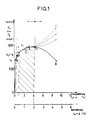
- the invention is based on the consideration that when precisely defined flow and multiaxial states are brought about in the bolt material, in particular by utilizing the kinematic strain hardening and the increased transverse tensile strength in the case of multiaxial, in particular triaxial, stress / strain states, a flow zone progressing locally in the notched bolt region with increasing longitudinal load produces can be, on the one hand, due to the constant volume with plastic deformation according to the relationship about 0.5 With (Transverse elongation) and (Longitudinal elongation) while dissolving the axial frictional forces of the shrink connection leads to a completely uniform thinning of the bolt. It also stabilizes due to the kinematic strain hardening the plastic transverse contraction while avoiding breakage due to instability at a level that is still in the area of the uniform expansion - ie between points E and H of the flow curve.
- the strain hardening parameter D and the natural maximum load elongation are in an area around a plastic thinning of the bolt 1.0% to 2.0% is permitted, which is basically sufficient to be able to loosen and tighten axially even very tight plug-in foot bolts, but also other shrink connections with a large overall length.
- the plug-in foot bolts 1 - hereinafter referred to as bolts for short - in the bores of the webs of the steam turbine wheel disc head and the webs (forks) of the plug-in feet are known - the moving blade plug-in wheel-wheel head connection from the steam outlet-side bolt end by means of a portable drilling device Type except for a boring-technically unproblematic residual wall thickness of 0.1d ... 0.15d, where d means the bolt diameter and the smaller value applies to bolts of smaller diameter, drilled centrally like a blind hole over almost the entire bolt length.
- a high-strength, solid pressure mandrel 3 is inserted into the axial bore 2 thus created, and its end protruding from the axial bore is then subjected to pressure from the riveting press 4, which is usually used for riveting the bolts, and the bolt is plastically elongated, whereby - due to the volume constancy - a thinning of the Bolzens results. Due to the strain hardening of the bolt material, there is a "flow shaft" progressing over the bolt length, which leads to such a reduction in the axial frictional forces that the bolt can ultimately be pressed out with relatively little force after the rivet head located on the steam inlet side has been separated beforehand .
- the plastic transverse contraction is generated by pulling over screwed-in tension pins 5.
- the bolt 1 is hollow drilled from both sides to a residual wall thickness of 0.1d ... 0.15d as centrally as possible, whereby a central piece 6 of a certain length can remain undrilled.
- the middle piece can also be omitted, whereby a through hole is created from both sides.
- a or a fine thread is cut in its initial area, the core diameter of which is equal to the bore diameter of the hollow-drilled bolt.
- two tension pins 5 protruding from the bores which should generally be made of a higher-strength material than the bolt material, are screwed in.
- the tensile force on the traction pins 5 is exerted simultaneously from both sides by means of two hydraulic presses, the hydraulic presses being supported on the inner end against the side surfaces of the wheel disc head 7 perpendicular to the pin axis and on the outer end against inner side surfaces of the intermediate plates 8 which engage the traction pins with play, which in turn are supported by their outer side surfaces bear against the inner side surfaces of nuts 9 screwed onto the tension pins with radially smaller dimensions in comparison to the intermediate plates 8.
- the hydraulic press acting on the traction pin 5 on the steam inlet side can also be omitted and replaced by an equally long disk, plate or similar spacing bridging element.
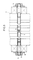
- the bolt 1 is at both ends with a relatively short, z. B. 60 mm long, stepped axial bore 2.
- Each axial bore has a rear blind hole-like part of the bore, which is provided with a fine thread 12, which forms a screw connection with the fine thread at the associated end of a draw bolt 13, which is stepped as weakly as possible and is dimensioned accordingly.
- the above-mentioned bore part is preceded by a cylindrical bore part which is larger in diameter and which has a cylindrical smooth extension 10 of length in its input region L ⁇ ⁇ R x S R ⁇ has a fine thread 14 adjoining the inside, which connects with the fine thread of a tension sleeve 15, the thread core diameter of which is equal to the diameter of the extension 10, with a limitation of the load on the inner tension sleeve 15 and the beginning of the blind hole-like part of the bore
- Pull sleeve 15 serving, cylindrically smooth expansion neck 16, the diameter of which is equal to the core diameter of the sleeve thread, is assigned.
- the pulling sleeve 15 which has a constant outer diameter, protrudes from the axial bore 2 and is provided with a fine thread 17 at its outstanding end.
- the tension bolt 13 passes through the tension sleeve 15, protrudes laterally from the tension sleeve 15 and is provided with a fine thread 18 at its outstanding end.
- the core diameter at the two ends of the tension sleeve 15 and the tension bolt 13 are each of the same size.
- the front thread of the tension bolt 13 forms, with the internal thread, an outer nut 19 which is designed as an expansion nut - that is to say a nut in which the tension in the entire volume is the same - in the radial direction - an outer nut 19.
- the front thread of the tension sleeve 15 forms a screw connection with the internal thread of an inner nut 20 designed as an expansion nut.
- the expansion cross sections of the nuts 19, 20 are dimensioned in accordance with the distribution of the tensile force between the tension bolt 13 and the tension sleeve 15.
- the inner inner nut head surface 21, which is perpendicular to the longitudinal central axis of the bolt 1, serves as a contact surface for the outer outer nut head surface 22, which is also directed perpendicular to the longitudinal central axis of the bolt 1.
- the organ of a hydraulic press acted upon by the pressure medium presses against the inner outer nut head surface 21 and presses against the inside supports side surface of the wheel disc head 7 oriented perpendicular to the longitudinal axis of the bolt.
- the hydraulic press, the nuts 19, 20 and the protruding ends of the draw bolt 13 and the draw sleeve 15 are surrounded by a safety hood 11.
- the above-described solution variant almost doubles the tensile force that can be introduced (longitudinal force), which results in a yield point of the bolt material of approximately 650 to 700 for the plastic transverse contraction also of the undrilled bolt section is sufficient.
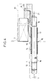
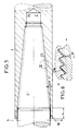
- the exemplary embodiment shown in FIG. 5 differs from the exemplary embodiment according to FIG. 3 in that the axial bore or - if the bolt ends each have a bore - the axial bores as in the example according to FIG Figure 4 is or are relatively short and that the tension pin (s) 5 are conical in their screw-in area and have a low-expansion saw thread.
- the or each axial bore 2 has a cylindrical, smooth starting part 10 of length L ⁇ ⁇ R xs R ⁇ , a conical intermediate part 23 provided with a low radial expansion thread and a cylindrical, smooth outlet part 24.
- the thread of the intermediate part and the thread of the associated threaded pin cone form a screw connection, via which the tensile forces are introduced into the bolt 1.
- the threads are preferably saw threads 23a with flank angles ⁇ between 0 ° and 15 ° (see FIG. 6).
- the angle of inclination of the cone depends on the manufacturability of the thread in the bolt locomotive using a tap.
- the thread cone if the thread pitch is selected to be 0.75 to 1 mm, the angle of inclination is approximately 5.7 ° (tan ⁇ ⁇ 0.1) and the flank angle is 15 °.
- Each tension pin 5 ' consists of a conical screw-in part, a cylindrical intermediate part and a cylindrical end part provided with a metric thread.
- the metric thread of the tension pin forms a screw connection with the internal thread of a nut, expansion screw or the like, the inner surface of the nut, of the expansion screw head or the like oriented perpendicular to the longitudinal axis of the bolt serving as a direct or indirect contact surface for the pressure-exerting element of the hydraulic press.
- a centering sleeve can be provided, which engages over the tension pin in its central part and finds its axial stop on the side surface of the wheel disc head 7.
- the bolt extraction process takes place in principle as in the exemplary embodiment according to FIG. 3.
- the bolt 1 should be plastically elongated over the entire length and, consequently, thinned before it is pulled out. This can be done by pulling on both sides by means of hydraulic presses or the like; However, it is also sufficient to only hold against an element according to FIG. 5 on the side that is difficult to access and to exert tension on the easily accessible side by means of the hydraulic press. After reaching the maximum load, the element on the hard-to-reach side is removed so that the bolt 1 can then be pulled out.
- the forces acting on the thread flanks and the resulting tensions are entered in FIG.
- ⁇ u 1 E ( 1 2nd ⁇ L - ⁇ PL ⁇ ⁇ L ) ⁇ 0 da ⁇ PL ⁇ 0.5
Landscapes
- Engineering & Computer Science (AREA)
- Mechanical Engineering (AREA)
- General Engineering & Computer Science (AREA)
- Hand Tools For Fitting Together And Separating, Or Other Hand Tools (AREA)
- Automatic Assembly (AREA)
- Heat Treatment Of Articles (AREA)
- Processing Of Solid Wastes (AREA)
- Forging (AREA)
- Insertion Pins And Rivets (AREA)
- Storage Of Web-Like Or Filamentary Materials (AREA)
- Lining Or Joining Of Plastics Or The Like (AREA)
- Turbine Rotor Nozzle Sealing (AREA)
Priority Applications (1)
| Application Number | Priority Date | Filing Date | Title |
|---|---|---|---|
| AT89114526T ATE83961T1 (de) | 1988-08-10 | 1989-08-07 | Verfahren und vorrichtung zum ausbauen von langen, aus zaehem werkstoff bestehenden innenkoerpern aus gebohrten elementen von schrumpfverbindungen. |
Applications Claiming Priority (2)
| Application Number | Priority Date | Filing Date | Title |
|---|---|---|---|
| DE3827036 | 1988-08-10 | ||
| DE3827036A DE3827036A1 (de) | 1988-08-10 | 1988-08-10 | Verfahren und vorrichtungen zum ausbauen von langen, aus zaehem werkstoff bestehenden innenkoerpern aus gebohrten elementen von schrumpfverbindungen |
Publications (3)
| Publication Number | Publication Date |
|---|---|
| EP0354509A2 EP0354509A2 (de) | 1990-02-14 |
| EP0354509A3 EP0354509A3 (en) | 1990-08-01 |
| EP0354509B1 true EP0354509B1 (de) | 1992-12-30 |
Family
ID=6360525
Family Applications (1)
| Application Number | Title | Priority Date | Filing Date |
|---|---|---|---|
| EP89114526A Expired - Lifetime EP0354509B1 (de) | 1988-08-10 | 1989-08-07 | Verfahren und Vorrichtung zum Ausbauen von langen, aus zähem Werkstoff bestehenden Innenkörpern aus gebohrten Elementen von Schrumpfverbindungen |
Country Status (9)
| Country | Link |
|---|---|
| US (1) | US5022136A (enExample) |
| EP (1) | EP0354509B1 (enExample) |
| JP (1) | JPH02152732A (enExample) |
| CN (1) | CN1018532B (enExample) |
| AT (1) | ATE83961T1 (enExample) |
| DE (2) | DE3827036A1 (enExample) |
| ES (1) | ES2037921T3 (enExample) |
| GR (1) | GR3007360T3 (enExample) |
| ZA (1) | ZA896120B (enExample) |
Cited By (1)
| Publication number | Priority date | Publication date | Assignee | Title |
|---|---|---|---|---|
| CN107520798A (zh) * | 2017-08-23 | 2017-12-29 | 重庆齿轮箱有限责任公司 | 一种圆螺母预紧结构及预紧方法 |
Families Citing this family (8)
| Publication number | Priority date | Publication date | Assignee | Title |
|---|---|---|---|---|
| US5117548A (en) * | 1991-05-20 | 1992-06-02 | The Babcock & Wilcox Company | Apparatus for loosening a mechanical plug in a heat exchanger tube |
| US6389692B1 (en) * | 2000-12-15 | 2002-05-21 | General Electric Company | Method for removing stuck locking pin in turbine rotor |
| KR100907128B1 (ko) * | 2002-07-24 | 2009-07-09 | 제너럴 일렉트릭 캄파니 | 도브테일 핀 제거 방법 |
| SE530690C2 (sv) | 2006-04-04 | 2008-08-12 | Alfa Laval Corp Ab | Rotorenhet för en centrifugalseparator |
| FR2980724B1 (fr) * | 2011-10-04 | 2014-10-17 | Airbus Operations Sas | Procede de destruction d'une fixation aveugle et dispositif pour sa mise en oeuvre |
| CN102513778A (zh) * | 2011-11-23 | 2012-06-27 | 广州文冲船厂有限责任公司 | 一种取出螺栓而无损螺栓孔的方法 |
| CN104254696B (zh) * | 2012-03-07 | 2017-05-10 | 株式会社近畿 | 填充部件的脱离方法及其所使用的填充部件及采用了该填充部件的切断刀 |
| JP5538468B2 (ja) * | 2012-03-30 | 2014-07-02 | 株式会社日立製作所 | タービン動翼とタービンロータのピン結合部の加工方法及びタービン動翼 |
Citations (1)
| Publication number | Priority date | Publication date | Assignee | Title |
|---|---|---|---|---|
| GB373167A (en) * | 1931-02-10 | 1932-05-10 | Einar Ameen | Improvements in or relating to manufacture of hollow drill steel |
Family Cites Families (8)
| Publication number | Priority date | Publication date | Assignee | Title |
|---|---|---|---|---|
| GB373165A (en) * | 1931-01-08 | 1932-05-09 | Verkaufsvereinigung Fuer Teere | Improvements in or relating to the manufacture of carbon electrodes |
| US2366142A (en) * | 1943-07-14 | 1944-12-26 | Allis Chalmers Mfg Co | Blade shrouding |
| DE1098960B (de) * | 1959-05-14 | 1961-02-09 | Westinghouse Electric Corp | Laufschaufelbefestigung bei Kreiselmaschinen mittels Steckbolzen |
| JPS5584804A (en) * | 1978-12-20 | 1980-06-26 | Hitachi Ltd | Structure for fixing rotor blade |
| GB2043796B (en) * | 1979-03-10 | 1983-04-20 | Rolls Royce | Bladed rotor for gas turbine engine |
| US4400137A (en) * | 1980-12-29 | 1983-08-23 | Elliott Turbomachinery Co., Inc. | Rotor assembly and methods for securing a rotor blade therewithin and removing a rotor blade therefrom |
| US4800637A (en) * | 1987-12-07 | 1989-01-31 | Combustion Engineering, Inc. | Method of removing plugs |
| US4903392A (en) * | 1988-06-22 | 1990-02-27 | Westinghouse Electric Corp. | Method for removing a metallic plug from a tube by simultaneously heating and stretching the plug |
-
1988
- 1988-08-10 DE DE3827036A patent/DE3827036A1/de active Granted
-
1989
- 1989-08-07 DE DE8989114526T patent/DE58903157D1/de not_active Expired - Fee Related
- 1989-08-07 ES ES198989114526T patent/ES2037921T3/es not_active Expired - Lifetime
- 1989-08-07 AT AT89114526T patent/ATE83961T1/de not_active IP Right Cessation
- 1989-08-07 EP EP89114526A patent/EP0354509B1/de not_active Expired - Lifetime
- 1989-08-09 US US07/390,951 patent/US5022136A/en not_active Expired - Fee Related
- 1989-08-10 CN CN89107606A patent/CN1018532B/zh not_active Expired
- 1989-08-10 JP JP1207785A patent/JPH02152732A/ja active Pending
- 1989-08-10 ZA ZA896120A patent/ZA896120B/xx unknown
-
1993
- 1993-03-16 GR GR930400561T patent/GR3007360T3/el unknown
Patent Citations (1)
| Publication number | Priority date | Publication date | Assignee | Title |
|---|---|---|---|---|
| GB373167A (en) * | 1931-02-10 | 1932-05-10 | Einar Ameen | Improvements in or relating to manufacture of hollow drill steel |
Cited By (1)
| Publication number | Priority date | Publication date | Assignee | Title |
|---|---|---|---|---|
| CN107520798A (zh) * | 2017-08-23 | 2017-12-29 | 重庆齿轮箱有限责任公司 | 一种圆螺母预紧结构及预紧方法 |
Also Published As
| Publication number | Publication date |
|---|---|
| ATE83961T1 (de) | 1993-01-15 |
| ES2037921T3 (es) | 1993-07-01 |
| CN1041809A (zh) | 1990-05-02 |
| ZA896120B (en) | 1990-05-30 |
| US5022136A (en) | 1991-06-11 |
| GR3007360T3 (enExample) | 1993-07-30 |
| JPH02152732A (ja) | 1990-06-12 |
| EP0354509A3 (en) | 1990-08-01 |
| DE3827036A1 (de) | 1990-02-15 |
| CN1018532B (zh) | 1992-10-07 |
| DE58903157D1 (de) | 1993-02-11 |
| DE3827036C2 (enExample) | 1991-06-06 |
| EP0354509A2 (de) | 1990-02-14 |
Similar Documents
| Publication | Publication Date | Title |
|---|---|---|
| EP4038271B1 (de) | Windenergieanlagenrotorblatt und verfahren zum verbinden zweier rotorblattsegmente | |
| DE69007478T2 (de) | Stauch-verbindungselement mit einer weit abstehenden schelle. | |
| DE102006019405B4 (de) | Werkzeug zur Kaltexpansion von Löchern | |
| DE3420360C2 (de) | Verwendung eines mit einem Gewinde versehenen Befestigungselements sowie Verfahren zum Setzen desselben | |
| EP2558230B1 (de) | Expansionskopf für aufweitwerkzeuge und diesen umfassendes expansionswerkzeug | |
| EP0748942A1 (de) | Verbindungssystem und Verfahren zum lösbaren festen Verbinden zweier Bauteile | |
| EP2957363B1 (de) | Mechanischer rohrexpander | |
| DE68915629T2 (de) | Blindbefestiger. | |
| EP0354509B1 (de) | Verfahren und Vorrichtung zum Ausbauen von langen, aus zähem Werkstoff bestehenden Innenkörpern aus gebohrten Elementen von Schrumpfverbindungen | |
| DE1804673B2 (de) | Verfahren zur Herstellung einer Kraftfahrzeug-Hohlachse | |
| DE1934339A1 (de) | Verfahren und Vorrichtung zum dauerhaften Verbinden von umlaufenden Teilen,wie Wellenteilen od.dgl.,mittels Kerbverzahnung | |
| WO2020088708A1 (de) | Vorgespannte wälzlagerung | |
| DE3033909C2 (de) | Verbindungselement | |
| DE3203231A1 (de) | Verfahren und vorrichtung zum kaltschmieden von innenprofilierten rohrkoerpern | |
| EP0483660B1 (de) | Passniet für hochbeanspruchte Nietverbindungen | |
| DE4112591C1 (enExample) | ||
| DE2445252A1 (de) | Wellenverbindung und verfahren zur verbindung einer welle mit einer nabe zwecks uebertragung grosser drehmomente | |
| EP4414566B1 (de) | Lösbarer spreizbolzen, verbindungsanordnung sowie verfahren zum erstellen einer solchen verbindungsanordnung | |
| DE102008060571A1 (de) | Montagevorrichtung für ein Rotorsystem einer Axial-Strömungsmaschine | |
| WO1994015110A1 (de) | Kupplung | |
| DE4140311A1 (de) | Wellenkupplungselement | |
| EP1452758B1 (de) | Wellenflanschverbindung und Verfahren zum Herstellen einer derartigen Wellenflanschverbindung | |
| EP2254714B1 (de) | Verfahren zum herstellen eines innengewindeelementes, innengewindeelement sowie schraubverbindung | |
| EP3863780B1 (de) | Verfahren und vorrichtung zum einprägen von oberflächenstrukturen in eine innenseite eines rohrs oder eines ventilschafts eines tellerventils | |
| DE102019002187B4 (de) | Verfahren und Vorrichtung zum Herstellen eines Bauteils mit Gewinde |
Legal Events
| Date | Code | Title | Description |
|---|---|---|---|
| PUAI | Public reference made under article 153(3) epc to a published international application that has entered the european phase |
Free format text: ORIGINAL CODE: 0009012 |
|
| AK | Designated contracting states |
Kind code of ref document: A2 Designated state(s): AT BE CH DE ES FR GB GR IT LI LU NL SE |
|
| PUAL | Search report despatched |
Free format text: ORIGINAL CODE: 0009013 |
|
| AK | Designated contracting states |
Kind code of ref document: A3 Designated state(s): AT BE CH DE ES FR GB GR IT LI LU NL SE |
|
| 17P | Request for examination filed |
Effective date: 19910102 |
|
| 17Q | First examination report despatched |
Effective date: 19910725 |
|
| GRAA | (expected) grant |
Free format text: ORIGINAL CODE: 0009210 |
|
| AK | Designated contracting states |
Kind code of ref document: B1 Designated state(s): AT BE CH DE ES FR GB GR IT LI LU NL SE |
|
| REF | Corresponds to: |
Ref document number: 83961 Country of ref document: AT Date of ref document: 19930115 Kind code of ref document: T |
|
| REF | Corresponds to: |
Ref document number: 58903157 Country of ref document: DE Date of ref document: 19930211 |
|
| GBT | Gb: translation of ep patent filed (gb section 77(6)(a)/1977) |
Effective date: 19930120 |
|
| ITF | It: translation for a ep patent filed | ||
| ET | Fr: translation filed | ||
| PGFP | Annual fee paid to national office [announced via postgrant information from national office to epo] |
Ref country code: ES Payment date: 19930518 Year of fee payment: 5 |
|
| PGFP | Annual fee paid to national office [announced via postgrant information from national office to epo] |
Ref country code: SE Payment date: 19930521 Year of fee payment: 5 |
|
| PGFP | Annual fee paid to national office [announced via postgrant information from national office to epo] |
Ref country code: GR Payment date: 19930528 Year of fee payment: 5 |
|
| REG | Reference to a national code |
Ref country code: GR Ref legal event code: FG4A Free format text: 3007360 |
|
| PGFP | Annual fee paid to national office [announced via postgrant information from national office to epo] |
Ref country code: LU Payment date: 19930701 Year of fee payment: 5 |
|
| REG | Reference to a national code |
Ref country code: ES Ref legal event code: FG2A Ref document number: 2037921 Country of ref document: ES Kind code of ref document: T3 |
|
| PGFP | Annual fee paid to national office [announced via postgrant information from national office to epo] |
Ref country code: NL Payment date: 19930831 Year of fee payment: 5 Ref country code: AT Payment date: 19930831 Year of fee payment: 5 |
|
| PLBE | No opposition filed within time limit |
Free format text: ORIGINAL CODE: 0009261 |
|
| STAA | Information on the status of an ep patent application or granted ep patent |
Free format text: STATUS: NO OPPOSITION FILED WITHIN TIME LIMIT |
|
| EPTA | Lu: last paid annual fee | ||
| 26N | No opposition filed | ||
| PG25 | Lapsed in a contracting state [announced via postgrant information from national office to epo] |
Ref country code: LU Free format text: LAPSE BECAUSE OF NON-PAYMENT OF DUE FEES Effective date: 19940807 Ref country code: AT Effective date: 19940807 |
|
| PG25 | Lapsed in a contracting state [announced via postgrant information from national office to epo] |
Ref country code: SE Effective date: 19940808 Ref country code: ES Free format text: LAPSE BECAUSE OF THE APPLICANT RENOUNCES Effective date: 19940808 |
|
| EAL | Se: european patent in force in sweden |
Ref document number: 89114526.0 |
|
| PG25 | Lapsed in a contracting state [announced via postgrant information from national office to epo] |
Ref country code: GR Free format text: THE PATENT HAS BEEN ANNULLED BY A DECISION OF A NATIONAL AUTHORITY Effective date: 19950228 |
|
| PG25 | Lapsed in a contracting state [announced via postgrant information from national office to epo] |
Ref country code: NL Effective date: 19950301 |
|
| NLV4 | Nl: lapsed or anulled due to non-payment of the annual fee | ||
| REG | Reference to a national code |
Ref country code: GR Ref legal event code: MM2A Free format text: 3007360 |
|
| EUG | Se: european patent has lapsed |
Ref document number: 89114526.0 |
|
| PGFP | Annual fee paid to national office [announced via postgrant information from national office to epo] |
Ref country code: DE Payment date: 19960422 Year of fee payment: 8 |
|
| PGFP | Annual fee paid to national office [announced via postgrant information from national office to epo] |
Ref country code: BE Payment date: 19960430 Year of fee payment: 8 |
|
| PGFP | Annual fee paid to national office [announced via postgrant information from national office to epo] |
Ref country code: FR Payment date: 19960524 Year of fee payment: 8 |
|
| PGFP | Annual fee paid to national office [announced via postgrant information from national office to epo] |
Ref country code: GB Payment date: 19960618 Year of fee payment: 8 |
|
| PGFP | Annual fee paid to national office [announced via postgrant information from national office to epo] |
Ref country code: CH Payment date: 19960715 Year of fee payment: 8 |
|
| PG25 | Lapsed in a contracting state [announced via postgrant information from national office to epo] |
Ref country code: GB Free format text: LAPSE BECAUSE OF NON-PAYMENT OF DUE FEES Effective date: 19970807 |
|
| PG25 | Lapsed in a contracting state [announced via postgrant information from national office to epo] |
Ref country code: LI Free format text: LAPSE BECAUSE OF NON-PAYMENT OF DUE FEES Effective date: 19970831 Ref country code: CH Free format text: LAPSE BECAUSE OF NON-PAYMENT OF DUE FEES Effective date: 19970831 Ref country code: BE Free format text: LAPSE BECAUSE OF NON-PAYMENT OF DUE FEES Effective date: 19970831 |
|
| BERE | Be: lapsed |
Owner name: S.A. GEC ALSTHOM Effective date: 19970831 |
|
| GBPC | Gb: european patent ceased through non-payment of renewal fee |
Effective date: 19970807 |
|
| REG | Reference to a national code |
Ref country code: CH Ref legal event code: PL |
|
| PG25 | Lapsed in a contracting state [announced via postgrant information from national office to epo] |
Ref country code: FR Free format text: LAPSE BECAUSE OF NON-PAYMENT OF DUE FEES Effective date: 19980430 |
|
| PG25 | Lapsed in a contracting state [announced via postgrant information from national office to epo] |
Ref country code: DE Free format text: LAPSE BECAUSE OF NON-PAYMENT OF DUE FEES Effective date: 19980501 |
|
| REG | Reference to a national code |
Ref country code: FR Ref legal event code: ST |
|
| REG | Reference to a national code |
Ref country code: ES Ref legal event code: FD2A Effective date: 19991007 |
|
| PG25 | Lapsed in a contracting state [announced via postgrant information from national office to epo] |
Ref country code: IT Free format text: LAPSE BECAUSE OF NON-PAYMENT OF DUE FEES;WARNING: LAPSES OF ITALIAN PATENTS WITH EFFECTIVE DATE BEFORE 2007 MAY HAVE OCCURRED AT ANY TIME BEFORE 2007. THE CORRECT EFFECTIVE DATE MAY BE DIFFERENT FROM THE ONE RECORDED. Effective date: 20050807 |