US5022136A - Method and a device for removing an elongate shrink-fitted core made of a tough material from a hole - Google Patents
Method and a device for removing an elongate shrink-fitted core made of a tough material from a hole Download PDFInfo
- Publication number
- US5022136A US5022136A US07/390,951 US39095189A US5022136A US 5022136 A US5022136 A US 5022136A US 39095189 A US39095189 A US 39095189A US 5022136 A US5022136 A US 5022136A
- Authority
- US
- United States
- Prior art keywords
- core
- bolt
- force
- traction
- hole
- Prior art date
- Legal status (The legal status is an assumption and is not a legal conclusion. Google has not performed a legal analysis and makes no representation as to the accuracy of the status listed.)
- Expired - Fee Related
Links
- 238000000034 method Methods 0.000 title claims abstract description 27
- 239000000463 material Substances 0.000 title abstract description 19
- 230000008878 coupling Effects 0.000 claims abstract description 4
- 238000010168 coupling process Methods 0.000 claims abstract description 4
- 238000005859 coupling reaction Methods 0.000 claims abstract description 4
- 239000007787 solid Substances 0.000 claims description 5
- 238000005520 cutting process Methods 0.000 claims description 4
- 239000002184 metal Substances 0.000 claims 2
- 230000008602 contraction Effects 0.000 description 8
- 238000005553 drilling Methods 0.000 description 5
- 230000006872 improvement Effects 0.000 description 5
- 238000007711 solidification Methods 0.000 description 5
- 230000008023 solidification Effects 0.000 description 5
- 230000000694 effects Effects 0.000 description 4
- 238000000605 extraction Methods 0.000 description 4
- 230000009467 reduction Effects 0.000 description 4
- 238000004519 manufacturing process Methods 0.000 description 3
- 230000008901 benefit Effects 0.000 description 2
- 238000009826 distribution Methods 0.000 description 2
- 238000005192 partition Methods 0.000 description 2
- 238000003825 pressing Methods 0.000 description 2
- 230000002250 progressing effect Effects 0.000 description 2
- VYZAMTAEIAYCRO-UHFFFAOYSA-N Chromium Chemical compound [Cr] VYZAMTAEIAYCRO-UHFFFAOYSA-N 0.000 description 1
- 241000237970 Conus <genus> Species 0.000 description 1
- 230000005483 Hooke's law Effects 0.000 description 1
- 238000004873 anchoring Methods 0.000 description 1
- 238000005452 bending Methods 0.000 description 1
- 230000008859 change Effects 0.000 description 1
- 229910052804 chromium Inorganic materials 0.000 description 1
- 239000011651 chromium Substances 0.000 description 1
- 230000006835 compression Effects 0.000 description 1
- 238000007906 compression Methods 0.000 description 1
- 238000011109 contamination Methods 0.000 description 1
- 239000008358 core component Substances 0.000 description 1
- 230000003111 delayed effect Effects 0.000 description 1
- 230000001627 detrimental effect Effects 0.000 description 1
- 239000013013 elastic material Substances 0.000 description 1
- 238000010438 heat treatment Methods 0.000 description 1
- 239000010720 hydraulic oil Substances 0.000 description 1
- 230000013011 mating Effects 0.000 description 1
- 238000005457 optimization Methods 0.000 description 1
- 230000003647 oxidation Effects 0.000 description 1
- 238000007254 oxidation reaction Methods 0.000 description 1
- 230000035515 penetration Effects 0.000 description 1
- 238000004513 sizing Methods 0.000 description 1
- 230000003068 static effect Effects 0.000 description 1
- 230000001629 suppression Effects 0.000 description 1
Images


Classifications
-
- B—PERFORMING OPERATIONS; TRANSPORTING
- B23—MACHINE TOOLS; METAL-WORKING NOT OTHERWISE PROVIDED FOR
- B23P—METAL-WORKING NOT OTHERWISE PROVIDED FOR; COMBINED OPERATIONS; UNIVERSAL MACHINE TOOLS
- B23P11/00—Connecting or disconnecting metal parts or objects by metal-working techniques not otherwise provided for
-
- B—PERFORMING OPERATIONS; TRANSPORTING
- B23—MACHINE TOOLS; METAL-WORKING NOT OTHERWISE PROVIDED FOR
- B23P—METAL-WORKING NOT OTHERWISE PROVIDED FOR; COMBINED OPERATIONS; UNIVERSAL MACHINE TOOLS
- B23P19/00—Machines for simply fitting together or separating metal parts or objects, or metal and non-metal parts, whether or not involving some deformation; Tools or devices therefor so far as not provided for in other classes
- B23P19/02—Machines for simply fitting together or separating metal parts or objects, or metal and non-metal parts, whether or not involving some deformation; Tools or devices therefor so far as not provided for in other classes for connecting objects by press fit or for detaching same
- B23P19/025—For detaching only
-
- F—MECHANICAL ENGINEERING; LIGHTING; HEATING; WEAPONS; BLASTING
- F01—MACHINES OR ENGINES IN GENERAL; ENGINE PLANTS IN GENERAL; STEAM ENGINES
- F01D—NON-POSITIVE DISPLACEMENT MACHINES OR ENGINES, e.g. STEAM TURBINES
- F01D25/00—Component parts, details, or accessories, not provided for in, or of interest apart from, other groups
- F01D25/24—Casings; Casing parts, e.g. diaphragms, casing fastenings
- F01D25/243—Flange connections; Bolting arrangements
-
- F—MECHANICAL ENGINEERING; LIGHTING; HEATING; WEAPONS; BLASTING
- F01—MACHINES OR ENGINES IN GENERAL; ENGINE PLANTS IN GENERAL; STEAM ENGINES
- F01D—NON-POSITIVE DISPLACEMENT MACHINES OR ENGINES, e.g. STEAM TURBINES
- F01D5/00—Blades; Blade-carrying members; Heating, heat-insulating, cooling or antivibration means on the blades or the members
- F01D5/30—Fixing blades to rotors; Blade roots ; Blade spacers
- F01D5/3053—Fixing blades to rotors; Blade roots ; Blade spacers by means of pins
-
- F—MECHANICAL ENGINEERING; LIGHTING; HEATING; WEAPONS; BLASTING
- F05—INDEXING SCHEMES RELATING TO ENGINES OR PUMPS IN VARIOUS SUBCLASSES OF CLASSES F01-F04
- F05D—INDEXING SCHEME FOR ASPECTS RELATING TO NON-POSITIVE-DISPLACEMENT MACHINES OR ENGINES, GAS-TURBINES OR JET-PROPULSION PLANTS
- F05D2230/00—Manufacture
- F05D2230/70—Disassembly methods
-
- Y—GENERAL TAGGING OF NEW TECHNOLOGICAL DEVELOPMENTS; GENERAL TAGGING OF CROSS-SECTIONAL TECHNOLOGIES SPANNING OVER SEVERAL SECTIONS OF THE IPC; TECHNICAL SUBJECTS COVERED BY FORMER USPC CROSS-REFERENCE ART COLLECTIONS [XRACs] AND DIGESTS
- Y10—TECHNICAL SUBJECTS COVERED BY FORMER USPC
- Y10T—TECHNICAL SUBJECTS COVERED BY FORMER US CLASSIFICATION
- Y10T29/00—Metal working
- Y10T29/49—Method of mechanical manufacture
- Y10T29/49316—Impeller making
- Y10T29/49318—Repairing or disassembling
-
- Y—GENERAL TAGGING OF NEW TECHNOLOGICAL DEVELOPMENTS; GENERAL TAGGING OF CROSS-SECTIONAL TECHNOLOGIES SPANNING OVER SEVERAL SECTIONS OF THE IPC; TECHNICAL SUBJECTS COVERED BY FORMER USPC CROSS-REFERENCE ART COLLECTIONS [XRACs] AND DIGESTS
- Y10—TECHNICAL SUBJECTS COVERED BY FORMER USPC
- Y10T—TECHNICAL SUBJECTS COVERED BY FORMER US CLASSIFICATION
- Y10T29/00—Metal working
- Y10T29/49—Method of mechanical manufacture
- Y10T29/49815—Disassembling
- Y10T29/49821—Disassembling by altering or destroying work part or connector
-
- Y—GENERAL TAGGING OF NEW TECHNOLOGICAL DEVELOPMENTS; GENERAL TAGGING OF CROSS-SECTIONAL TECHNOLOGIES SPANNING OVER SEVERAL SECTIONS OF THE IPC; TECHNICAL SUBJECTS COVERED BY FORMER USPC CROSS-REFERENCE ART COLLECTIONS [XRACs] AND DIGESTS
- Y10—TECHNICAL SUBJECTS COVERED BY FORMER USPC
- Y10T—TECHNICAL SUBJECTS COVERED BY FORMER US CLASSIFICATION
- Y10T29/00—Metal working
- Y10T29/49—Method of mechanical manufacture
- Y10T29/49815—Disassembling
- Y10T29/49822—Disassembling by applying force
-
- Y—GENERAL TAGGING OF NEW TECHNOLOGICAL DEVELOPMENTS; GENERAL TAGGING OF CROSS-SECTIONAL TECHNOLOGIES SPANNING OVER SEVERAL SECTIONS OF THE IPC; TECHNICAL SUBJECTS COVERED BY FORMER USPC CROSS-REFERENCE ART COLLECTIONS [XRACs] AND DIGESTS
- Y10—TECHNICAL SUBJECTS COVERED BY FORMER USPC
- Y10T—TECHNICAL SUBJECTS COVERED BY FORMER US CLASSIFICATION
- Y10T29/00—Metal working
- Y10T29/53—Means to assemble or disassemble
- Y10T29/53996—Means to assemble or disassemble by deforming
Definitions
- the invention relates to a method of removing elongate shrink-fitted shafts, bolts or similar cores made of tough material from hubs or holes.
- the invention further relates to devices for implementing the method according to the preamble of claims 4 and 7.
- a coupling member which projects laterally from an axial bore in the core and which may be connected to a traction device, or else a solid bolt comprising an axiallY projecting end which may be loaded by a pressure device is inserted into said axial bore which, as the case may be, is previously cut into said core as coaxially as possible;
- the core is made to shrink radially, whereby after the deformation has begun, the core is loaded at a relatively low speed up to a maximum stress of between 95% and 97% of its rupture strength;
- the core is extracted or ejected from the bore, if necessary after previously cutting off a terminal expanded area such as a rivet head or similar.
- the application of the inventive method to the removal of blade bolts from steam turbines further entails the advantage that the additional nominal stress area required for the design of the blade connections can be totally or partially omitted.
- the additional nominal stress area required for the design of the blade connections can be totally or partially omitted.
- Another advantage of the method consists in the fact that ridges in the bore of the drilled elements can be totally or largely avoided which otherwise would appear due to the jamming and jam release phenomena.
- the axial bore between the end of the thread and the end of the core comprises a smooth cylindrical portion, the inside diameter of which is equal to the outside diameter of the fine screw thread and the length of which is selected according to the formula L ⁇ R ⁇ S R .
- Said cylindrical portion ensures the effect that the radial expansion rate at the screw end is relatively low.
- the risk of a radial expansion can be further reduced or avoided by realizing the fine screw thread according to a further improvement of the invention as a sawtooth thread or similar thread of low radial expansion.
- a further improvement of the device of the invention consists in the fact that each traction pin, each traction bolt and the associated core components are cone-shaped, that the threads are sawtooth threads or similar threads with low radial expansion and with bearing edge angles between 0° and 15° C., and that the conical bore in the core is followed by a smooth cylindrical portion, the diameter of which is equal to the largest outside diameter of the conical thread of the traction bolt and the length of which is selected according to the formula L ⁇ R ⁇ S R .
- the conical shape of the pins or bolts results in an optimization of the useful cross-sections.
- the thread with a low radial expansion and the smooth cylindrical portions are required because of the low residual wall thickness of the core as, otherwise, the core may tear.
- each thread cone may include two portions with equal or unequal cone inclination, equal or unequal thread pitch and equal or unequal bearing edge angles.
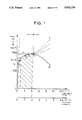
- FIG. 1 is the stress/strain graph in the longitudinal and transverse directions for the material of the bolt.
- FIG. 2 represents the method steps of a first example of the method.
- FIG. 3 is a fragmentary cross-section of a second example using an extraction device.
- FIG. 4 shows a third example, partially in cross-section, and using a different extraction device.
- FIG. 5 shows a detail of the third extraction device in connection with a conical thread.
- FIG. 6 is a detail of FIG. 5 showing a conical sawtooth thread.
- FIG. 7 is a cross-section through a part of a modified short core axial bore with a conical thread having two portions.
- FIG. 8 shows the distribution of forces and stresses around the edges of the thread.
- FIG. 9 shows the delayed beginning of creep in the residual section due to a defined two-axial tensile strength state.
- the reduction of the cross-section of the bolt by drawing the bolt up to the plastic deformation region is based on the static stress/strain curve ⁇ O ( ⁇ ) or ⁇ W ( ⁇ ) of the bolt material as shown in FIG. 1.
- the curve can be subdivided into the following zones:
- F-H range of elongation up to the point of maximum load H prior to necking and instability, and giving rise to a relatively high plastic elongation and transverse contraction.
- the technical interest for the use according to the invention is primarily directed to the hatched zone in FIG. 1 preceding maximum load point H beyond which further elongation only induces a small change in tensile stress.
- H-T takes place after a certain degree of solidification.
- This stress state allows for example at locally restricted points of force transfer to obtain a stress level which technically can be used in the range of ⁇ T / ⁇ 0 .2 ⁇ 1.45 . . . 1.80 times the yield limit of the classically used bolt material.
- creep phenomena can be induced in the zones which are primarily subjected to uniaxial stress at a level ⁇ Z of ⁇ Z / ⁇ 0 .2 ⁇ 1.10 . . . 1.25, which creep phenomena are sufficient for the required transverse contraction of the bolt.
- the invention is based on the idea that by creating well-defined creep states and states of pluriaxiality in the bolt material, especially by using the kinematic solidification of the elongation as well as the increased resistance to transversal traction in pluriaxial, especially tri-axial stress/elongation states, a locally progressing creep zone can be produced in the unnotched bolt area at increasing longitudinal stress which, due to the principle of constant volume in plastic deformation according to the relation ⁇ d/d O ⁇ 0.5 ⁇ 1/1 O with ⁇ d/d O being the transversal elongation and ⁇ 1/1 O being the longitudinal elongation, causes a completely uniform diameter reduction of the bolt and a suppression of the axial friction forces of the shrink-fitting. Moreover, the plastic transversal contraction becomes stabilized due to the kinematic solidification of elongation
- the parameter of elongation solidification D and the natural elongation at highest load ⁇ H 1n(1 H /1 O ) are situated in a region in which a plastic cross-section reduction of the bolt ( ⁇ d/d O )pl of 1% to 2% is permitted, which is basically sufficient for loosening and axially removing even very tightly-fitted blade finger bolts, but also other shrink fittings of considerable length.
- the blade bolts 1 shrink-fitted into bores of the stems of steam turbine wheel disk heads and of the stems (forks) of the blade fingers will be referred hereafter as "bolts" for short and are provided over nearly their entire bolt length by means of a movable drilling machine of known type applied to the bolt end situated at the steam outlet side with a central bore thereby leaving only a residual wall thickness of 0.1d to 0.15d with d being the bolt diameter and the smaller value being applied to bolts of smaller diameters. This thickness does not present anY drilling problem.
- a very hard and solid pressure pin 3 is inserted into this axial bore 2 and the pin end projecting from the axial bore is then pressure-loaded by the rivet press 4 which is normally used to rivet the bolts.
- the plastic transversal contraction is caused by applying a traction force to traction pins 5 engaged by screwing.
- a hole as central as possible is drilled from both sides into the bolt, leaving only a residual wall thickness of 0.1d to 0.15d, thereby leaving a central partition 6 of a given length between the holes.
- the central partition may also be eliminated, which signifies that a through-passage is drilled from both sides.
- a fine screw thread is cut into the area close to the outer end, the core diameter of this thread being equal to the diameter of the bore in the bolt.
- two traction pins 5 which in general should be made of a harder material than the bolt are screwed into the bore.
- the traction force of the traction pins 5 is applied by means of two hydraulic jacks simultaneously from both sides, the hydraulic jacks being applied on their inner side against the lateral surfaces of the wheel disk head 7 perpendicular to the bolt axis and at the outer end against the inner lateral surfaces of the intermediate plates 8 surrounding the traction pins with clearance, the intermediate plates 8 being applied by their outer lateral surfaces to the inner lateral surfaces of nuts 9 screwed on the traction pins, these nuts having a smaller size in radial direction than the intermediate plates 8.
- the hydraulic jack acting on the traction pin 5' on the side of steam entry can be omitted and be replaced by a disk of the same length, a plate or similar element for compensating for the distance.
- the notch traction strength ⁇ BK ⁇ BK ( ⁇ k ) which can be achieved at a tri-axial stress state does not exceed the value of about 1100 N/mm 2 .
- the same considerations are applicable to both screwed-in traction pins 5 with ⁇ Z ⁇ 0 .2 for the unnotched areas of the pin.
- the residual wall thickness of 2.5 mm in the case of a 18 mm bolt and a unilateral bore of a depth between 100 and 120 mm does not present any major problem in consideration of usual drilling precision and of deviations.
- the axial bores 2 are provided in their entry area between the beginning of the bore and the end of the bolt with a smooth (unnotched) cylindrical zone 10, the diameter of which equals the outside diameter of the thread, the length of which is defined by the empirical formula L ⁇ R ⁇ S R with R being the wall thickness of the cylinder and R the average radius of the cylinder, and/or screw threads having a low radial expansion such as sawtooth threads with precisely defined edge angles are used, these measures reducing the danger of a radial expansion and a turning out.
- the axial bore must be made as coaxially as possible to the longitudinal axis of the bolt and the screw thread must be made perpendicularly to the lateral surface of the wheel disk head 7 in order to avoid an additional bending and expansion.
- the bolt 1 may now be withdrawn, and this may be supported by slight hammer impacts on the end of the bolt on the less accessible side.
- a safety sleeve or cap in view of a possible rupture of the threads, the pin or the bolt, a safety sleeve or cap must be secured above the hydraulic jacks and the traction pins 5.
- the anchoring of the safety sleeves can be ensured in the threads of the adjacent bolts in case of bolt connections having several rows.
- the bolt 1 is provided at both of its ends with a relatively short stepped axial bore 2, for example 60 mm long.
- Each axial bore presents a rear blind hole portion on which a fine screw thread 12 is made constituting a connection with the fine screw thread at the respective end of a conveniently sized traction bolt 13 which preferably is only slightly stepped.
- This blind hole portion is followed by a cylindrical portion of larger diameter which presents at its inlet area a smooth cylindrical portion of a length L ⁇ R ⁇ S R , this portion being followed towards the inside by a fine screw thread 14 cooperating with the fine screw thread of a traction sleeve 15 having a thread core diameter equal to the diameter of the portion 10.
- a smooth cylindrical collar 16 of a diameter equal to the core diameter of the sleeve thread is provided which serves to restrict the stress of the traction sleeve 15.
- the traction sleeve 15 which presents a constant outer diameter, projects from the axial bore 2 and is provided at its projecting end with a fine screw thread 17.
- the traction bolt 13 passes through the traction sleeve 15, projects laterally from the traction sleeve 15 and is provided at its projecting end with a fine screw thread 18.
- the core diameter at the two ends of the traction sleeve 15 and the traction bolt 13 are respectively the same.
- the front side thread of the traction bolt 13 constitutes a screw connection together with the inner thread of an outer nut 19 (as seen in radial direction) which acts as an elongation nut, i.e. a nut in which the tensile strength is the same in the entire volume.
- the front side thread of the traction sleeve 15 constitutes a screw connection together with the inner nut 20 acting as elongation nut.
- the elongation sections of the nuts 19 and 20 are sized according to the distribution of the traction force on the traction bolts 13 and the traction sleeve 15.
- the inner surface 21 of the inner nut head perpendicular to the longitudinal axis of the bolt 1 acts as abutment surface for the outer surface of the outer nut head which is also perpendicular to the longitudinal axis of the bolt 1.
- the pressure actuated member of a hydraulic jack which is applied on the inner side against the lateral surface of the wheel disk head 7 directed perpendicularly to the bolt longitudinal axis is applied against the inner surface 21 of the outer nut head.
- the hydraulic jack, the nuts 19 and 20, and the projecting ends of the traction bolt 13 and of the traction sleeve 15 are surrounded by a safety cap 11.
- the material of the traction bolts 13 and the traction sleeves 15 should be as hard as possible.
- the improvement described above allows almost the double traction force (longitudinal force) to be transferred, which is sufficient also to obtain a transverse contraction of the solid bolt section, if the yield point of the bolt material is between 650 and 700 N/mm 2 .
- FIG. 5 distinguishes over the embodiment according to FIG. 3 by the fact that the axial bore or the axial bores if both bolt ends are provided with a bore as is shown in the embodiment of FIG. 4, is or are respectively relatively short, and that the at least one traction pin 5' is conically shaped in the screwing area and presents a sawtooth thread of low elongation.
- Each axial bore 2 comprises a cylindrical smooth entry portion 10 of a length L ⁇ R ⁇ S R , a conical intermediate portion 23 having a thread with a low radial expansion and a smooth cylindrical end portion 24.
- the thread in the intermediate portion and the thread of the respective cone of the threaded pin constitute a screw connection through which traction forces can be transferred into the bolt 1.
- the threads are preferably sawtooth threads 23a with bearing edge angles ⁇ between 0° and 15° C. (see FIG. 6).
- the angle of inclination of the cone depends on the facility of manufacturing of the thread in the bolt bore by means of a thread cutter.
- the threaded cone As far as the threaded cone is concerned, it is further useful to select the thread pitch between 0.75 and 1 mm, the angle of inclination at about 5.7° (tan ⁇ 0.1) and the bearing edge angle at 15°.
- Each traction pin 5' consists of a conical thread portion, a cylindrical intermediate portion and a cylindrical end portion provided with a metric thread.
- This metric screw thread of the traction pin constitutes a screw connection with the inner thread of a nut, elongation screw or similar, the inner surface of the nut, the elongation screw head or similar directed perpendicularly to the longitudinal bolt axis, acting directly or indirectly as abutting surface for the actuator member of the hydraulic jack.
- a centering sleeve can be provided for centering the hydraulic jack, this sleeve extending beyond the intermediate portion of the pin and abutting against the side surface of the wheel disk head 7.
- a conus tip may be used having two thread portions whereby the inclination angle, the thread pitch and the bearing edge angle of both sections must not be the same (FIG. 7).
- tensile strengths of nearly 920 N/mm 2 can be achieved in the solid bolt cross-section O--O.
- the yield point of the traction pin 5' in the cross-section 4--4 must not be higher than about 1200 N/mm 2 , a value which can be achieved securely for very hard materials and which can be supported as often as necessary.
- the method of removing the bolt is in general performed according to the embodiment shown in FIG. 3. It should however be avoided to apply traction only from one side and to contract the bolt from the steam outlet side because this necessarily entails deep ridges in the bores of the wheel disks and the blades.
- the bolt 1 should be plastically elongated over its entire length and, as a consequence, should be reduced in cross-section before being extracted. This can be achieved by applying traction on both sides by means of hydraulic jacks or similar means. But it is also sufficient to only hold a member according to FIG. 5 against the side of reduced accessibility and to apply a traction force by the hydraulic jack at the side of good accessibility. When the highest load has been obtained, the member on the hardly accessible side is withdrawn in order to allow the extraction of the bolt 1.
- FIG. 8 the forces applied to the thread edges and the resulting tensile stresses are indicated.
- ⁇ u (0.5 ⁇ u - ⁇ PL ⁇ L )/E ⁇ O as ⁇ PL ⁇ 0.5
Landscapes
- Engineering & Computer Science (AREA)
- Mechanical Engineering (AREA)
- General Engineering & Computer Science (AREA)
- Hand Tools For Fitting Together And Separating, Or Other Hand Tools (AREA)
- Automatic Assembly (AREA)
- Heat Treatment Of Articles (AREA)
- Processing Of Solid Wastes (AREA)
- Forging (AREA)
- Insertion Pins And Rivets (AREA)
- Storage Of Web-Like Or Filamentary Materials (AREA)
- Lining Or Joining Of Plastics Or The Like (AREA)
- Turbine Rotor Nozzle Sealing (AREA)
Applications Claiming Priority (2)
| Application Number | Priority Date | Filing Date | Title |
|---|---|---|---|
| DE3827036 | 1988-08-10 | ||
| DE3827036A DE3827036A1 (de) | 1988-08-10 | 1988-08-10 | Verfahren und vorrichtungen zum ausbauen von langen, aus zaehem werkstoff bestehenden innenkoerpern aus gebohrten elementen von schrumpfverbindungen |
Publications (1)
| Publication Number | Publication Date |
|---|---|
| US5022136A true US5022136A (en) | 1991-06-11 |
Family
ID=6360525
Family Applications (1)
| Application Number | Title | Priority Date | Filing Date |
|---|---|---|---|
| US07/390,951 Expired - Fee Related US5022136A (en) | 1988-08-10 | 1989-08-09 | Method and a device for removing an elongate shrink-fitted core made of a tough material from a hole |
Country Status (9)
| Country | Link |
|---|---|
| US (1) | US5022136A (enExample) |
| EP (1) | EP0354509B1 (enExample) |
| JP (1) | JPH02152732A (enExample) |
| CN (1) | CN1018532B (enExample) |
| AT (1) | ATE83961T1 (enExample) |
| DE (2) | DE3827036A1 (enExample) |
| ES (1) | ES2037921T3 (enExample) |
| GR (1) | GR3007360T3 (enExample) |
| ZA (1) | ZA896120B (enExample) |
Cited By (6)
| Publication number | Priority date | Publication date | Assignee | Title |
|---|---|---|---|---|
| US5117548A (en) * | 1991-05-20 | 1992-06-02 | The Babcock & Wilcox Company | Apparatus for loosening a mechanical plug in a heat exchanger tube |
| US6389692B1 (en) * | 2000-12-15 | 2002-05-21 | General Electric Company | Method for removing stuck locking pin in turbine rotor |
| KR100907128B1 (ko) * | 2002-07-24 | 2009-07-09 | 제너럴 일렉트릭 캄파니 | 도브테일 핀 제거 방법 |
| CN102513778A (zh) * | 2011-11-23 | 2012-06-27 | 广州文冲船厂有限责任公司 | 一种取出螺栓而无损螺栓孔的方法 |
| US20150204373A1 (en) * | 2012-03-07 | 2015-07-23 | Naoya Wada | Detaching method of filling member and filling member used therein and cutter blade using this filling member |
| US9550192B2 (en) | 2006-04-04 | 2017-01-24 | Alfa Laval Corporate Ab | Rotor unit for a centrifugal separator having undetachably joined separating discs |
Families Citing this family (3)
| Publication number | Priority date | Publication date | Assignee | Title |
|---|---|---|---|---|
| FR2980724B1 (fr) * | 2011-10-04 | 2014-10-17 | Airbus Operations Sas | Procede de destruction d'une fixation aveugle et dispositif pour sa mise en oeuvre |
| JP5538468B2 (ja) * | 2012-03-30 | 2014-07-02 | 株式会社日立製作所 | タービン動翼とタービンロータのピン結合部の加工方法及びタービン動翼 |
| CN107520798B (zh) * | 2017-08-23 | 2019-04-02 | 重庆齿轮箱有限责任公司 | 一种圆螺母预紧结构及预紧方法 |
Citations (8)
| Publication number | Priority date | Publication date | Assignee | Title |
|---|---|---|---|---|
| GB373167A (en) * | 1931-02-10 | 1932-05-10 | Einar Ameen | Improvements in or relating to manufacture of hollow drill steel |
| US2366142A (en) * | 1943-07-14 | 1944-12-26 | Allis Chalmers Mfg Co | Blade shrouding |
| DE1098960B (de) * | 1959-05-14 | 1961-02-09 | Westinghouse Electric Corp | Laufschaufelbefestigung bei Kreiselmaschinen mittels Steckbolzen |
| DE2951176A1 (de) * | 1978-12-20 | 1980-07-10 | Hitachi Ltd | Turbinenschaufel-befestigungsanordnung |
| DE3008889A1 (de) * | 1979-03-10 | 1980-09-11 | Rolls Royce | Beschaufelter rotor fuer ein gasturbinentriebwerk |
| EP0055415A1 (en) * | 1980-12-29 | 1982-07-07 | Carrier Corporation | A rotor assembly and methods of securing a rotor blade therewithin and removing a rotor blade therefrom |
| US4800637A (en) * | 1987-12-07 | 1989-01-31 | Combustion Engineering, Inc. | Method of removing plugs |
| EP0347584A2 (en) * | 1988-06-22 | 1989-12-27 | Westinghouse Electric Corporation | Method and apparatus for removing a metallic plug from a tube by simultaneously heating and stretching the plug |
Family Cites Families (1)
| Publication number | Priority date | Publication date | Assignee | Title |
|---|---|---|---|---|
| GB373165A (en) * | 1931-01-08 | 1932-05-09 | Verkaufsvereinigung Fuer Teere | Improvements in or relating to the manufacture of carbon electrodes |
-
1988
- 1988-08-10 DE DE3827036A patent/DE3827036A1/de active Granted
-
1989
- 1989-08-07 DE DE8989114526T patent/DE58903157D1/de not_active Expired - Fee Related
- 1989-08-07 ES ES198989114526T patent/ES2037921T3/es not_active Expired - Lifetime
- 1989-08-07 AT AT89114526T patent/ATE83961T1/de not_active IP Right Cessation
- 1989-08-07 EP EP89114526A patent/EP0354509B1/de not_active Expired - Lifetime
- 1989-08-09 US US07/390,951 patent/US5022136A/en not_active Expired - Fee Related
- 1989-08-10 CN CN89107606A patent/CN1018532B/zh not_active Expired
- 1989-08-10 JP JP1207785A patent/JPH02152732A/ja active Pending
- 1989-08-10 ZA ZA896120A patent/ZA896120B/xx unknown
-
1993
- 1993-03-16 GR GR930400561T patent/GR3007360T3/el unknown
Patent Citations (11)
| Publication number | Priority date | Publication date | Assignee | Title |
|---|---|---|---|---|
| GB373167A (en) * | 1931-02-10 | 1932-05-10 | Einar Ameen | Improvements in or relating to manufacture of hollow drill steel |
| US2366142A (en) * | 1943-07-14 | 1944-12-26 | Allis Chalmers Mfg Co | Blade shrouding |
| DE1098960B (de) * | 1959-05-14 | 1961-02-09 | Westinghouse Electric Corp | Laufschaufelbefestigung bei Kreiselmaschinen mittels Steckbolzen |
| DE2951176A1 (de) * | 1978-12-20 | 1980-07-10 | Hitachi Ltd | Turbinenschaufel-befestigungsanordnung |
| US4321012A (en) * | 1978-12-20 | 1982-03-23 | Hitachi, Ltd. | Turbine blade fastening construction |
| DE3008889A1 (de) * | 1979-03-10 | 1980-09-11 | Rolls Royce | Beschaufelter rotor fuer ein gasturbinentriebwerk |
| GB2043796A (en) * | 1979-03-10 | 1980-10-08 | Rolls Royce | Bladed rotor for gas turbine engine |
| EP0055415A1 (en) * | 1980-12-29 | 1982-07-07 | Carrier Corporation | A rotor assembly and methods of securing a rotor blade therewithin and removing a rotor blade therefrom |
| US4400137A (en) * | 1980-12-29 | 1983-08-23 | Elliott Turbomachinery Co., Inc. | Rotor assembly and methods for securing a rotor blade therewithin and removing a rotor blade therefrom |
| US4800637A (en) * | 1987-12-07 | 1989-01-31 | Combustion Engineering, Inc. | Method of removing plugs |
| EP0347584A2 (en) * | 1988-06-22 | 1989-12-27 | Westinghouse Electric Corporation | Method and apparatus for removing a metallic plug from a tube by simultaneously heating and stretching the plug |
Cited By (7)
| Publication number | Priority date | Publication date | Assignee | Title |
|---|---|---|---|---|
| US5117548A (en) * | 1991-05-20 | 1992-06-02 | The Babcock & Wilcox Company | Apparatus for loosening a mechanical plug in a heat exchanger tube |
| US6389692B1 (en) * | 2000-12-15 | 2002-05-21 | General Electric Company | Method for removing stuck locking pin in turbine rotor |
| KR100907128B1 (ko) * | 2002-07-24 | 2009-07-09 | 제너럴 일렉트릭 캄파니 | 도브테일 핀 제거 방법 |
| US9550192B2 (en) | 2006-04-04 | 2017-01-24 | Alfa Laval Corporate Ab | Rotor unit for a centrifugal separator having undetachably joined separating discs |
| CN102513778A (zh) * | 2011-11-23 | 2012-06-27 | 广州文冲船厂有限责任公司 | 一种取出螺栓而无损螺栓孔的方法 |
| US20150204373A1 (en) * | 2012-03-07 | 2015-07-23 | Naoya Wada | Detaching method of filling member and filling member used therein and cutter blade using this filling member |
| US10072696B2 (en) * | 2012-03-07 | 2018-09-11 | Kabushiki Kaisha Kinki | Detaching method of filling member and filling member used therein and cutter blade using this filling member |
Also Published As
| Publication number | Publication date |
|---|---|
| ATE83961T1 (de) | 1993-01-15 |
| ES2037921T3 (es) | 1993-07-01 |
| CN1041809A (zh) | 1990-05-02 |
| ZA896120B (en) | 1990-05-30 |
| GR3007360T3 (enExample) | 1993-07-30 |
| JPH02152732A (ja) | 1990-06-12 |
| EP0354509A3 (en) | 1990-08-01 |
| DE3827036A1 (de) | 1990-02-15 |
| CN1018532B (zh) | 1992-10-07 |
| DE58903157D1 (de) | 1993-02-11 |
| EP0354509B1 (de) | 1992-12-30 |
| DE3827036C2 (enExample) | 1991-06-06 |
| EP0354509A2 (de) | 1990-02-14 |
Similar Documents
| Publication | Publication Date | Title |
|---|---|---|
| US8621734B2 (en) | Collet for a low swage load fastening system | |
| CN1332134C (zh) | 用于模锻套环的具有拉槽的拉杆紧固件 | |
| US5022136A (en) | Method and a device for removing an elongate shrink-fitted core made of a tough material from a hole | |
| US4472096A (en) | Optimized fastener construction system and method | |
| CZ281543B6 (cs) | Šroub pro děrování a vytváření závitu | |
| CA2666810C (en) | Fast extraction threaded nut | |
| AU2002350958B2 (en) | Method of fastening | |
| US5810530A (en) | Interference blind type bolt | |
| EP2251118A1 (en) | Collet for a low swage load fastening installation tool | |
| EP3212434A1 (de) | Verfahren zur herstellung eines fahrzeugrads mit einer verbindung zwischen einer radfelge und einer radscheibe | |
| US5036727A (en) | Connecting bolt and assembly | |
| KR20080015130A (ko) | 리벳 | |
| US5557835A (en) | Method, Rivet-Punch, for joining several metal sheets by using non-heat-treated rivets made from an aluminium alloy | |
| EP3366970A1 (en) | Hydraulic plug | |
| US6615636B2 (en) | Method and apparatus for improving the fatigue life of components and structures using the stresswave process | |
| US5594187A (en) | Forged powder metal connecting rod with stress riser crease formed in side thrust face | |
| EP4062073A1 (en) | Nutless bolt | |
| GB2145185A (en) | Two piece fastener for adjacent workpieces |
Legal Events
| Date | Code | Title | Description |
|---|---|---|---|
| AS | Assignment |
Owner name: SOCIETE ANONYME DITE: GEC ALSTHOM SA, FRANCE Free format text: ASSIGNMENT OF ASSIGNORS INTEREST.;ASSIGNOR:TREMMEL, DIETER;REEL/FRAME:005657/0104 Effective date: 19890710 |
|
| FEPP | Fee payment procedure |
Free format text: PAYOR NUMBER ASSIGNED (ORIGINAL EVENT CODE: ASPN); ENTITY STATUS OF PATENT OWNER: LARGE ENTITY |
|
| FPAY | Fee payment |
Year of fee payment: 4 |
|
| REMI | Maintenance fee reminder mailed | ||
| LAPS | Lapse for failure to pay maintenance fees | ||
| FP | Lapsed due to failure to pay maintenance fee |
Effective date: 19990611 |
|
| STCH | Information on status: patent discontinuation |
Free format text: PATENT EXPIRED DUE TO NONPAYMENT OF MAINTENANCE FEES UNDER 37 CFR 1.362 |