EP0354062B1 - Corner bracket and interconnection system for ducting - Google Patents
Corner bracket and interconnection system for ducting Download PDFInfo
- Publication number
- EP0354062B1 EP0354062B1 EP89307975A EP89307975A EP0354062B1 EP 0354062 B1 EP0354062 B1 EP 0354062B1 EP 89307975 A EP89307975 A EP 89307975A EP 89307975 A EP89307975 A EP 89307975A EP 0354062 B1 EP0354062 B1 EP 0354062B1
- Authority
- EP
- European Patent Office
- Prior art keywords
- bracket
- corner
- tab
- brackets
- leg
- Prior art date
- Legal status (The legal status is an assumption and is not a legal conclusion. Google has not performed a legal analysis and makes no representation as to the accuracy of the status listed.)
- Expired - Lifetime
Links
Images

Classifications
-
- F—MECHANICAL ENGINEERING; LIGHTING; HEATING; WEAPONS; BLASTING
- F24—HEATING; RANGES; VENTILATING
- F24F—AIR-CONDITIONING; AIR-HUMIDIFICATION; VENTILATION; USE OF AIR CURRENTS FOR SCREENING
- F24F13/00—Details common to, or for air-conditioning, air-humidification, ventilation or use of air currents for screening
- F24F13/02—Ducting arrangements
- F24F13/0209—Ducting arrangements characterised by their connecting means, e.g. flanges
-
- F—MECHANICAL ENGINEERING; LIGHTING; HEATING; WEAPONS; BLASTING
- F16—ENGINEERING ELEMENTS AND UNITS; GENERAL MEASURES FOR PRODUCING AND MAINTAINING EFFECTIVE FUNCTIONING OF MACHINES OR INSTALLATIONS; THERMAL INSULATION IN GENERAL
- F16L—PIPES; JOINTS OR FITTINGS FOR PIPES; SUPPORTS FOR PIPES, CABLES OR PROTECTIVE TUBING; MEANS FOR THERMAL INSULATION IN GENERAL
- F16L23/00—Flanged joints
- F16L23/12—Flanged joints specially adapted for particular pipes
- F16L23/14—Flanged joints specially adapted for particular pipes for rectangular pipes
-
- Y—GENERAL TAGGING OF NEW TECHNOLOGICAL DEVELOPMENTS; GENERAL TAGGING OF CROSS-SECTIONAL TECHNOLOGIES SPANNING OVER SEVERAL SECTIONS OF THE IPC; TECHNICAL SUBJECTS COVERED BY FORMER USPC CROSS-REFERENCE ART COLLECTIONS [XRACs] AND DIGESTS
- Y10—TECHNICAL SUBJECTS COVERED BY FORMER USPC
- Y10T—TECHNICAL SUBJECTS COVERED BY FORMER US CLASSIFICATION
- Y10T29/00—Metal working
- Y10T29/49—Method of mechanical manufacture
- Y10T29/49826—Assembling or joining
- Y10T29/49908—Joining by deforming
- Y10T29/49915—Overedge assembling of seated part
- Y10T29/49922—Overedge assembling of seated part by bending over projecting prongs
Definitions
- the present invention relates to a corner bracket constructed so as to allow back to back interconnection of the bracket to similar brackets.
- the brackets are particularly suited for use with flange jointing arrangements for air conditioning duct and the like.
- Mating fasteners used to date include bolts passing through facing corner brackets and clips which are slid over and bind the abutting flange pieces and/or corner brackets.
- this prior art concerns itself with methods of attaching flanges to the ends of air conditioning duct (or integrally forming flanges as part of the ends of air conditioning ducts) so as to allow for an airtight, long-lived joint between abutting duct sections.
- the flange and seal construction is only one contributor to a reliable air-tight duct joint.
- the other important contributor is the means by which adjacent, abutting flanges are bound together to form the joint.
- the prior art discloses a combination of overlapping clips as one primary means by which the binding means is effected.
- an L-shaped corner bracket comprising first and second legs which are substantially co-planar and perpendicular to one another, a corner region being defined at the intersection of said legs and having an aperture therethrough, characterised by an elongated bendable tab joined by one end to said bracket and aligned with one of said legs, the tab being bendable out of the plane of the bracket and over an outer edge of said corner region, thereby providing a means for clamping said bracket to a second similar corner bracket and thereby form said aperture through the corner region of the bracket.
- corner brackets are mounted on each corner of an end of an air conditioning duct to be abutted and subsequently joined, and all edges but one of the tab are detached from the bracket and the tab is bendable along the edge connected to the bracket out of the plane of the bracket to thereby form said aperture through the corner region of the bracket, the longitudinal centre line of said tab being aligned with the longitudinal centre line of said one of said legs.
- edge of the tab area left connected is that edge closest to the adjacent outer rim of said second leg when said tab is aligned with said first leg and wherein the edge of the tab left connected is that edge closest to the adjacent outer rim of said first leg when said tab is aligned with said second leg.
- said tab is waisted by having a centre portion of its longitudinal extent provided with a narrower width than the end portions thereof.
- said tab is of sufficient length to allow it to be bent around and thereby clamp at least an adjacent edge of an abutting second corner bracket.
- a system for joining two like ends of air conditioning ducts of substantially rectangular cross-section, each end having four coplanar partial flange members said system comprising eight L-shaped corner brackets arranged two for each corner of said duct, wherein each corner of the duct joint is secured by an abutting pair of said corner brackets arranged with the first leg of each bracket lying alongside the second leg of the other bracket, said bracket clamping said partial flange members and each said tab being bent out of the plane of the bracket away from the corresponding one leg and over the corner region of both brackets to maintain the clamping action and form said aperture through the corner region of the respective bracket.
- first and second brackets being aligned in abutment such that said first leg of said first bracket lies against said second leg of said second bracket whilst, at the same time, said second leg of said first bracket lies against said first leg of said second bracket; said method of interconnecting said first and second brackets comprising the steps of:
- each bracket is flat strips turned at the edges to provide stiffening ribs, said ribs also acting to provide purchase for said tabs when said tabs are folded over said ribs.
- said system of interconnected brackets is applied to cause abutted ends of generally square or rectangular cross section duct to be connected in permanently and firmly abutted relationship, the tabs of interconnected brackets thereby acting not just to clamp the bracket against which they immediately abut, but with all the other abutted corner brackets and partial flange members providing a composite, rigid duct interconnection.
- corner brackets for duct inter-connection are described below.
- the important features of both embodiments include the integral tabs formed in corner regions of the corner brackets and the integral, aligned bolt holes which result automatically from use of the tabs for the purposes of binding adjacent, abutting brackets together. These are the primary common features of the two embodiments but these should not be construed as being the only common or meritorious features.
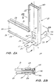
- Brackets 20, 21 of the first embodiment are shown abutting in Figure 2A.
- the closest bracket 20 comprises a first leg 22 and a second leg 23 joined at right angles at a corner region 24.
- a "tab area" 25 which, in this case, is generally rectangular in shape but nipped in at a waist region 26.
- the tab area 25 is aligned such that its longitudinal centre line is aligned with the longitudinal centre line of the first leg 22.
- the first and second legs of the bracket 20 are themselves punched from a single metal plate and have edge portions 28, 29 turned at right angles so as to provide strengthening ribs for the bracket and also to provide appropriate width for wedging purposes when inserted within receiving flange members (not shown).
- Additional wedging width can be provided if necessary by punching flared holes in the legs - the flares providing the desired interference fit within the flange members.
- Bracket 21 also shown in Figure 2A is identical in shape and construction to bracket 20.
- the brackets 20, 21 are shown abutted in such a way that the first leg 22 of bracket 20 lies against the corresponding second leg 30 of bracket 21 whilst the second leg 23 of bracket 20 lies against the first leg 31 of bracket 21.
- first leg is that leg which has the longitudinal centre line of the tab area 25 aligned with the leg centre line. (See the discussion in the second embodiment where the tab area is differently aligned.)
- the tab 32 of the second bracket 21 is found to inherently and automatically lie along the same longitudinal direction as the tab 27 of the first bracket 20 but rotated 90° about the longitudinal centre line axis relative to the tab 27.
- brackets are punched from galvanized steel plate of 1 to 3 mm thickness.
- the preferred thickness range for most purposes is 1.5 - 2.5 mm.
- a right angle rib is provided as shown (29) in Figure 2A for brackets of thickness 1.5 - 2 mm.
- brackets of thickness 2.5 - 3 mm In an alternative form a softer angled rib is provided for brackets of thickness 2.5 - 3 mm.
- bracket is made-from plate of 3 mm thickness or larger.
- bracket leg extension is around 75 mm for the thickness ranges given above.
- brackets all identical are punched from the steel plate, the edge ribbing effected and the tab punched from the corner area.
- holes 33, 34, 35, 36 are drilled in the tab area (or punched) to facilitate the bending of the tabs during corner mating on site.
- the above manufacturing steps are carried out by the one die punch operation on 150 mm wide steel plate stock.
- State of the art punching machinery can punch 3000 brackets per hour per die.
- air conditioning duct portions 27 and 38 are manufactured in a factory. Flange assemblies as generally shown applied to the edge of duct 38 are preferably applied at the factory (although this can be done on site if necessary).
- the flange assemblies comprise flange members 1, 2, 3, 4 which are affixed to the respective edge faces of the duct 38 or roll formed on the duct and are also interconnected by corner brackets 5, 6, 7, 8.
- the flange members are supplied by a number of manufacturers including DUCTMATE INDUSTRIES INC (of USA) and EXANNO PRODUCTS LIMITED (of Canada).
- the flange members are described in many prior art patents including US3443601, US4218079, US4466641, US3712650 and US4509778.
- the corner brackets 5, 6, 7, 8 are shaped according to the first embodiment just described.
- the corner brackets are applied such that the tab (27 of bracket 20) lies along the air conditioning duct work away from the duct work face to which the corner bracket is applied. (Again note that the alignment of the second embodiment tab is different to this.)
- the duct work complete with flange assemblies attached is transported to site, lifted into final position and abutting faces of the ducts 37, 38 brought into abutting relationship so that corner brackets 12 and 6 and corner brackets 13 and 7 form back to back pairs similar to the pair 20, 12 shown in Figure 2A.
- the corner brackets (and thereby the whole of the abutting flanges) are permanently attached to each other simply by the installation worker bending the tabs 27, 32 around the outer edge of the corner area of each corner bracket as generally shown in Figure 2A so that the tabs clamp against at least the turned edge portion 29, 39 of respective abutting brackets 20, 21.
- the completed arrangement is as generally shown in Figure 2B.
- the bent tabs hold the abutting corner brackets in a locked, non sliding relationship.
- each duct The fact that the four corner brackets on the end of each duct are themselves held in a fixed relation by virtue of their attachment to the duct creates the condition that the tabs interact with and bind not just the facing bracket to which they are immediately connected but also all the other corner brackets of the abutted assemblies of the duct to duct joint.
- the result is a very rigid, reliable duct connection which is capable of maintaining adequate pressure on sealing material placed between the mating flange and mating corner bracket surfaces at the connection so that an adequate air pressure seal is provided.
- a substantially square bolt hole is left in the corner area of the bracket assembly, the left and right sides of the bolt hole being formed by the waist 26 of the tab area 25 of bracket 20 whilst the top and bottom sides of the bolt hole 40 are formed by the waist of the tab area of bracket 21.
- This bolt hole can be used for the attachment of the corner bracket assembly to suspension systems or it can be used to accommodate bolts for the holding of auxiliary equipment to the duct work.
- brackets can be bolted together using the bolt holes.
- bracket by having integral fasteners, saves on total material as compared to equivalent prior art fastened bracket assemblies (typically, today, corner brackets joints using bolts require four bolts per duct joint at US 15 cents per bolt and 2-3 man minutes per joint. It is conservatively estimated that by not requiring separate bolts or other separate fasteners and by also needing less time for installation due to the fastening tabs of the first embodiment already being in position for the tradesman to work on some 120-200 million US dollars can be saved on air conditioning duct work installation in industrialized countries per year.
- a hole is automatically provided in the abutted corner brackets, which hole is free for use to support the duct work or to attach auxiliary equipment.
- the hole is not required for fasteners to hold the corner brackets together.
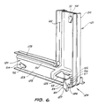
- bracket 27 in Figure 2A becomes tab 127 in Figure 6.
- the closest bracket 120 comprises a first leg 122 and a second leg 123 joined at right angles at a corner region 124.
- a "tab area” 125 which, in very broad terms, is generally rectangularly shaped (although having an offset, triangular shape at its end closest to the second leg 123).
- the tab area 125 is aligned so that its longitudinal centre line is aligned with the longitudinal centre line of the second leg 123.
- tab 127 has been punched from the tab area 125 and bent as illustrated in Figure 6 so as to lie generally parallel to the duct work face to which the first leg 122 is attached when the bracket 120 is applied to the flanges of the duct work. (i.e. the tab 127 is bent so as to lie parallel with the duct face aligned with the corner leg [first leg 122 in this case] as compared with the leg [second leg 123 in this case] along whose centre line the tab area [125 in this case] is aligned.)
- the first and second legs of the bracket 120 are themselves punched from a single metal plate and have edge portions 128, 129 turned at right angles to the general plane of the first leg 122 and second leg 123 so as to provide strengthening ribs for the leg and for the bracket and also to provide appropriate width for wedging purposes when inserted within receiving flange members (not shown, but see generally Figure 1 and the prior art specifications mentioned at the beginning of the specification).
- the opposed bracket 121 also shown in Figure 6, is identical in shape and construction to the bracket 120.
- the brackets 120, 121 are shown in adjacent, abutted relationship such that the first leg 122 of bracket 120 lies against second leg 130 of bracket 121 whilst the second leg 123 of bracket 120 lies against the first leg 131 of bracket 121.
- bracket of the first embodiment could not be mated with a bracket of the second embodiment for the purposes of carrying out the invention described in this specification.
- Bar holding tabs 51, 52 are punched near the extreme ends of the legs 122, 123 as generally shown in figure 3 and Figure 6.
- the tabs 51, 52 can be raised and bent so as to hold reinforcing bars and the like when site conditions dictate it (i.e. when extra large ducting requires reinforcement).
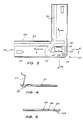
- a dimple 53 in the very corner of the corner region 124 is raised proud on the face of the corner bracket 120 opposite to the face in view in figure 3. This face is the "mating" face which will be abutted against an adjacent, abutting corner bracket (121 in Figure 6).
- the purpose of the dimple 53 is to bear against the opposing dimple of the adjacent, abutting corner bracket so that the mated corner bracket pair have sufficient width that they will remain wedged within the duct flanges into which the legs of the pair are inserted in use.
- Figure 28 of the first embodiment shows the dimples [un-numbered] bearing against each other.
- holes of approximately 2 to 2.5mm diameter perforate the bracket 120 as illustrated, for example, in Figure 6, so as to facilitate bending of the tabs punched therein.
- perforation hole 54 facilitates the bending of the bar holding tab 52 and the aligned perforations 55, 56, 57 and 58, 59, 60 define fold lines (and facilitate the bending about those fold lines) on tab 127.
- aligned perforations 61, 62, 63 (refer Figure 3) which facilitate bending about a further fold line located at the base of the tab 127.
- the tab outline is punched in the corner region 124 so that three of the tab's sides are separated from the surrounding corner region. These sides are nipped to form a waist region 126 as shown in Figure 3.
- part of the corner region 124 adjacent the waist region 126 of the tab 127 is flared upwardly in the same direction as the ribs 128, 129.
- Two angled ribs 64, 65 are thereby formed which, on the one hand, provide additional reinforcement to the bracket as a whole and also serve to thicken what will become two edges of a four edged bolt hole when like brackets are placed back to back and mechanically bound by the tab 127 as to be described hereunder.
- That portion of the tab 127 furthest away from its connection to the corner region 124 has an offset, triangular shape as generally shown in Figure 3.
- a score line 66 generally parallel to the other fold lines (defined by the perforations previously mention) is made for the purposes of facilitating bending of the apex region in an opposite direction to the direction of the folds made about the fold lines.
- the section of Figure 4 shows the tab 127 in a partly bent, elevated state, being bent approximately 90° about the fold line defined by the perforations 61, 62, 63 and being further bent by a further 90° about the fold line defined by the perforations 58, 59, 60 and finally being bent approximately 45° in the opposite direction about the score line 66.
- the second embodiment as illustrated in Figure 3 is drawn full size. And is made from galvanised steel approximately 1.5mm thick (16 gauge). The sections of Figure 4 and Figure 5 have been enlarged very slightly for clarity.
- the thickness of the metal from which the bracket is constructed can be varied dependent upon the size of the ducting to be connected. It is unlikely that the thickness will vary outside the range 1.5 - 2.5mm (16 - 12 gauge). It is highly unlikely that the thickness will need to range outside of 1.2 - 3mm (18 - 10 gauge). For very thick metal (e.g. 12 gauge) it may be necessary to actually cut partially along the proposed fold lines in order to allow sharp bends to be made on site with hand tools.
- the manufacturing process for the brackets of the second embodiment is the same as that for the first embodiment.
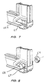
- brackets In use the brackets are assembled to the flanges on duct ends at the factory. The tabs are partially bent to the configuration shown in section in Figure 4. The ducts are then taken to site for installation. With the ducts supported in their final instalation position with flange and corner bracket assemblies in adjacent, abutting relationship (refer Figure 1) tabs of adjacent corner brackets are bent over both the outer rim of their own bracket and the outer rim of the bracket against which they abut. The brackets in abutting, adjacent relation ready for tab bending are shown in Figure 6. Adjacent brackets with tabs completely bent over are shown in Figure 7. The bending operation can be carried out by a worker using a hand tool such as a hammer or the like.
- the apex portion 67 of the tab bent about the score line 66 facilitates the closing down of the bent tab assembly neatly against the inside rim area of the bracket rim 129.
- the perforations along the fold lines facilitate bending using simple hand held tools but do not detract significantly from the strength of the resulting mechanical joint binding the adjacent, abutting corner brackets together.
- a seal (not shown) made from butyl mastic or the like is applied between the abutting faces of the flanges and corner brackets so as to be clamped therebetween when the corner bracket tabs are bent over to clamp all brackets of the joint as shown in Figure 7.
- the seal can also be made from closed cell neoprene or foam tape of non-combustible type.
- ducting has side lengths of less than 450mm it is possible to rely only upon the binding of the corner bracket tabs to effect and support the seal between the abutting duct portions.
- ducts having side lengths greater than 450mm require the use of additional connecting clamps to clamp the flanges of the ducts. Such clamps have been made the subject of at least some of the prior art specifications mentioned at the begining of this specification.
- the aperture exposed in the corner region 124 of the brackets by the bending of the tab 127 out to its final position is aligned with that portion of the aperture of the adjacent, abutting bracket which was vacated by the waist region of the tab of the adjacent, abutting bracket.
- the two abutting vacated regions rotated 90° with respect to each other, create a generally square aperture through the bound corner brackets.
- This aperture can accept a bolt 68 threaded there through screw clamped by a nut 69 as illustrated in Figure 8.
- this nut and bolt assembly can be used either to hold auxilliary equipment to the corner bracket.
- the spacing between the fold lines of the tab 127 is matched to the width of the adjacent, abutting corner brackets (including allowance for the abutting dimples 53).
- the location of the fold line perforations closest to where the tab 127 joins the corner region 124 is selected so as to provide a close fit for the tab against the rim 129 when in the bent, clamping condition.
- the brackets can be made from materials other than steel and can be applied wherever relatively large rectangular cross section duct work needs to be joined in an economical fashion. Zinc or cadmium plating can be used instead of galvanising.
- the tab area can be extended longitudinally or shortened as necessary to provide differing amounts of tab overlap.
- Serrations or scoring can be substituted for the holes used to facilitate bending.
Abstract
Description
- The present invention relates to a corner bracket constructed so as to allow back to back interconnection of the bracket to similar brackets. The brackets are particularly suited for use with flange jointing arrangements for air conditioning duct and the like.
- In the art of air conditioning duct jointing there are a number of prior art systems in use. Referring to Figure 1 all of the prior art systems have in common the application of flange kits to abutting ends of air conditioning duct to be joined. The kit for each end typically comprises
flange pieces corner brackets - On site the ducting complete with flange assemblies attached is lifted into its final installation location, the opposed flange assemblies of duct ends to be abutted are placed face to face with sealant material trapped between and a series of fasteners is then used to permanently mate the flanges of the abutted duct ends. Mating fasteners used to date include bolts passing through facing corner brackets and clips which are slid over and bind the abutting flange pieces and/or corner brackets.
- A selection of the possibly most relevant prior art includes US3443601 (Siegwart), US312650 (Mez), US4218079 (Arnoldt), US466641 (Heilman), US4509778 (Arnoldt) and US4558892.
- In general terms this prior art concerns itself with methods of attaching flanges to the ends of air conditioning duct (or integrally forming flanges as part of the ends of air conditioning ducts) so as to allow for an airtight, long-lived joint between abutting duct sections. Of course, the flange and seal construction is only one contributor to a reliable air-tight duct joint. The other important contributor is the means by which adjacent, abutting flanges are bound together to form the joint. The prior art discloses a combination of overlapping clips as one primary means by which the binding means is effected. The prior art (US4558892) also reveals that a system of corner brackets has evolved, which brackets are applied to duct corners in slotted mechanical inter-connection with the flange of which the corner bracket becomes a part. Adjacent, abutting corner brackets of adjacent, abutting duct ends are themselves bound together in a mechanically sealed manner. The primary binding method for binding these corner brackets has involved the use of threaded fasteners such as nut and-bolt assemblies passing through aligned holes in the very corners of adjacent, abutting corner brackets. US 4 558 892 and Figure 2 of US4509778 (Arnoldt) clearly show the aligned holes of adjacent, abutting corner brackets. Figure 11 of US4218079 (Arnoldt) clearly shows a cross section through bolted corner brackets.
- The prior art has not relied solely upon bolting as a means of binding corner brackets - for example the above refered figure 2 of US4509778 shows a clip which slides over and ends adjacent, abutting legs of adjacent, abutting corner brackets. However, in all cases known to the applicant, the binding operation and binding means for adjacent corner brackets has required the use of a component or components mechanically separate from either of the brackets being bound. The typical prior art bound corner bracket assembly has required four separate components - the two brackets and two clips or two brackets and one nut and one bolt.
- Disadvantages of these prior art corner bracket mating systems include:
- accurate aligning of mating corner brackets is critical to allow bolts to be threaded therethrough
- the fastener component(s) is/are an entirely separate article which must be transported to the final installation location and installed as an entirely separate item.
- It is an object of the present invention to provide corner brackets for duct flange systems and a method of installation of corner brackets for such flange systems which does away with the requirement for an entirely separate fastener for the corner brackets.
- It is a further object of the invention to provide a corner bracket binding system which will tolerate some missalignment, at least in the plane of the mating faces of abutting brackets.
- It is a further object of the present invention to provide a corner bracket which achieves one or more of the above mentioned objects and otherwise overcomes one or more of the above mentioned problems of the prior art and which will be useable with many, if not all, of the duct flange arrangements presently used in the air conditioning market.
- In accordance with one aspect of the present invention an L-shaped corner bracket is provided comprising first and second legs which are substantially co-planar and perpendicular to one another, a corner region being defined at the intersection of said legs and having an aperture therethrough, characterised by an elongated bendable tab joined by one end to said bracket and aligned with one of said legs, the tab being bendable out of the plane of the bracket and over an outer edge of said corner region, thereby providing a means for clamping said bracket to a second similar corner bracket and thereby form said aperture through the corner region of the bracket.
- Preferably the corner brackets are mounted on each corner of an end of an air conditioning duct to be abutted and subsequently joined, and all edges but one of the tab are detached from the bracket and the tab is bendable along the edge connected to the bracket out of the plane of the bracket to thereby form said aperture through the corner region of the bracket, the longitudinal centre line of said tab being aligned with the longitudinal centre line of said one of said legs.
- Preferably the edge of the tab area left connected is that edge closest to the adjacent outer rim of said second leg when said tab is aligned with said first leg and wherein the edge of the tab left connected is that edge closest to the adjacent outer rim of said first leg when said tab is aligned with said second leg.
- Preferably said tab is waisted by having a centre portion of its longitudinal extent provided with a narrower width than the end portions thereof.
- Preferably said tab is of sufficient length to allow it to be bent around and thereby clamp at least an adjacent edge of an abutting second corner bracket.
- In a further broad form there is provided a system for joining two like ends of air conditioning ducts of substantially rectangular cross-section, each end having four coplanar partial flange members, said system comprising eight L-shaped corner brackets arranged two for each corner of said duct, wherein each corner of the duct joint is secured by an abutting pair of said corner brackets arranged with the first leg of each bracket lying alongside the second leg of the other bracket, said bracket clamping said partial flange members and each said tab being bent out of the plane of the bracket away from the corresponding one leg and over the corner region of both brackets to maintain the clamping action and form said aperture through the corner region of the respective bracket.
- In a further broad form there is provided a method of interconnecting abutting first and second corner brackets, said first and second brackets being aligned in abutment such that said first leg of said first bracket lies against said second leg of said second bracket whilst, at the same time, said second leg of said first bracket lies against said first leg of said second bracket; said method of interconnecting said first and second brackets comprising the steps of:
- (a) bending the tab of said first bracket around the immediately adjacent outer rim of said first bracket and thence around the immediately adjacent outer rim of said second bracket; and
- (b) bending the tab of said second bracket around the immediately adjacent outer rim of said second bracket and thence around the immediately adjacent outer rim of said first bracket.
- Preferably the legs of each bracket are flat strips turned at the edges to provide stiffening ribs, said ribs also acting to provide purchase for said tabs when said tabs are folded over said ribs.
- In yet a further broad form said system of interconnected brackets is applied to cause abutted ends of generally square or rectangular cross section duct to be connected in permanently and firmly abutted relationship, the tabs of interconnected brackets thereby acting not just to clamp the bracket against which they immediately abut, but with all the other abutted corner brackets and partial flange members providing a composite, rigid duct interconnection.
- One embodiment of the invention will now be described with reference to the drawings wherein:
- Figure 1 shows a general arrangement of duct flanges and duct interconnection applicable both to the prior art and to the present invention, (corner brackets illustrated are according to the invention; flanges are prior art),
- Figure 2A shows two corner brackets according to a first embodiment in abutting relationship and
- Figure 2B shows a section through two abutting corner brackets of a first embodiment mechanically interconnected by their tabs
- Figure 3 shows a side view of a bracket of a second embodiment bracket,
- Figure 4 shows a section through the second embodiment of Figure 3 with the tab lifted,
- Figure 5 shows a further section view through the third embodiment of Figure 3,
- Figure 6 shows two brackets of the second embodiment in adjacent, abutting relationship as they would be in use as part of a flange joint with the tab binding members bent partly towards the bound position,
- Figure 7 shows further detail of the adjacent, abutting third embodiment brackets of Figure 6 with the tab members of both brackets bent entirely over so as to mechanically bind both brackets together and
- Figure 8 shows a nut and bolt assembly applied to the aligned hole formed in the corners of the adjacent, abutting brackets of Figures 6 and 7.
- Primarily, two embodiments of corner brackets for duct inter-connection are described below. The important features of both embodiments include the integral tabs formed in corner regions of the corner brackets and the integral, aligned bolt holes which result automatically from use of the tabs for the purposes of binding adjacent, abutting brackets together. These are the primary common features of the two embodiments but these should not be construed as being the only common or meritorious features.
- Two
brackets closest bracket 20 comprises afirst leg 22 and asecond leg 23 joined at right angles at acorner region 24. Within the corner region is a "tab area" 25 which, in this case, is generally rectangular in shape but nipped in at awaist region 26. Thetab area 25 is aligned such that its longitudinal centre line is aligned with the longitudinal centre line of thefirst leg 22. - In Figure 2A a
tab 27 had been punched from thetab area 25 and bent as illustrated in Figure 2A so as to lie along the duct work face when thebracket 20 is applied to an edge of the duct work. - The first and second legs of the
bracket 20 are themselves punched from a single metal plate and haveedge portions - Additional wedging width can be provided if necessary by punching flared holes in the legs - the flares providing the desired interference fit within the flange members.
- The
opposed bracket 21 also shown in Figure 2A is identical in shape and construction tobracket 20. Thebrackets first leg 22 ofbracket 20 lies against the correspondingsecond leg 30 ofbracket 21 whilst thesecond leg 23 ofbracket 20 lies against thefirst leg 31 ofbracket 21. - Note that in all cases in the first embodiment the "first leg" is that leg which has the longitudinal centre line of the
tab area 25 aligned with the leg centre line. (See the discussion in the second embodiment where the tab area is differently aligned.) - When the
brackets tab 32 of thesecond bracket 21 is found to inherently and automatically lie along the same longitudinal direction as thetab 27 of thefirst bracket 20 but rotated 90° about the longitudinal centre line axis relative to thetab 27. - In this embodiment the brackets are punched from galvanized steel plate of 1 to 3 mm thickness. The preferred thickness range for most purposes is 1.5 - 2.5 mm.
- In one form a right angle rib is provided as shown (29) in Figure 2A for brackets of thickness 1.5 - 2 mm.
- In an alternative form a softer angled rib is provided for brackets of thickness 2.5 - 3 mm.
- In yet another alternative form no rib is provided when the bracket is made-from plate of 3 mm thickness or larger.
- Usually the bracket leg extension is around 75 mm for the thickness ranges given above. Specifically the brackets (all identical) are punched from the steel plate, the edge ribbing effected and the tab punched from the corner area. In some circumstances holes 33, 34, 35, 36 are drilled in the tab area (or punched) to facilitate the bending of the tabs during corner mating on site.
- The above manufacturing steps are carried out by the one die punch operation on 150 mm wide steel plate stock. State of the art punching machinery can punch 3000 brackets per hour per die.
- Specifically, in use for the purposes of providing flanges for abutting ends of air conditioning duct work and their interconnection, the installation process is as follows:
Referring to Figure 1 airconditioning duct portions duct 38 are preferably applied at the factory (although this can be done on site if necessary). The flange assemblies compriseflange members duct 38 or roll formed on the duct and are also interconnected bycorner brackets - The
corner brackets ducts corner brackets corner brackets pair - The corner brackets (and thereby the whole of the abutting flanges) are permanently attached to each other simply by the installation worker bending the
tabs edge portion 29, 39 of respective abuttingbrackets - The fact that the four corner brackets on the end of each duct are themselves held in a fixed relation by virtue of their attachment to the duct creates the condition that the tabs interact with and bind not just the facing bracket to which they are immediately connected but also all the other corner brackets of the abutted assemblies of the duct to duct joint. The result is a very rigid, reliable duct connection which is capable of maintaining adequate pressure on sealing material placed between the mating flange and mating corner bracket surfaces at the connection so that an adequate air pressure seal is provided.
- Further, once the tabs are in the bent, interlocked position a substantially square bolt hole is left in the corner area of the bracket assembly, the left and right sides of the bolt hole being formed by the
waist 26 of thetab area 25 ofbracket 20 whilst the top and bottom sides of the bolt hole 40 are formed by the waist of the tab area ofbracket 21. This bolt hole can be used for the attachment of the corner bracket assembly to suspension systems or it can be used to accommodate bolts for the holding of auxiliary equipment to the duct work. - In isolated special cases where site conditions dictate that tabs are not accessible for bending, the brackets can be bolted together using the bolt holes.
- Advantages of the above described first embodiment assembly include:
Only one universal bracket need be produced. - The bracket, by having integral fasteners, saves on total material as compared to equivalent prior art fastened bracket assemblies (typically, today, corner brackets joints using bolts require four bolts per duct joint at US 15 cents per bolt and 2-3 man minutes per joint. It is conservatively estimated that by not requiring separate bolts or other separate fasteners and by also needing less time for installation due to the fastening tabs of the first embodiment already being in position for the tradesman to work on some 120-200 million US dollars can be saved on air conditioning duct work installation in industrialized countries per year.
- A hole is automatically provided in the abutted corner brackets, which hole is free for use to support the duct work or to attach auxiliary equipment. The hole is not required for fasteners to hold the corner brackets together.
- With reference to Figures 3, 4, 5, 6, 7 and 8 a second embodiment of the corner bracket of the invention will now be described.
- In the following description components of the bracket of the second embodiment which generally correspond with components of the bracket of the first embodiment have been given the same identifying number but preceded by a 1.
e.g. tab 27 in Figure 2A becomestab 127 in Figure 6. Note, of course, that the structure oftab 27 and the structure oftab 127 is not identical. Referring to Figure 6 (of the second embodiment) and comparing it generally with Figure 2A (of the first embodiment) there is shown twobrackets closest bracket 120 comprises afirst leg 122 and asecond leg 123 joined at right angles at acorner region 124. Within thecorner region 124 is a "tab area" 125 which, in very broad terms, is generally rectangularly shaped (although having an offset, triangular shape at its end closest to the second leg 123). Thetab area 125 is aligned so that its longitudinal centre line is aligned with the longitudinal centre line of thesecond leg 123. - In
Figure 6a tab 127 has been punched from thetab area 125 and bent as illustrated in Figure 6 so as to lie generally parallel to the duct work face to which thefirst leg 122 is attached when thebracket 120 is applied to the flanges of the duct work. (i.e. thetab 127 is bent so as to lie parallel with the duct face aligned with the corner leg [first leg 122 in this case] as compared with the leg [second leg 123 in this case] along whose centre line the tab area [125 in this case] is aligned.) - The first and second legs of the
bracket 120 are themselves punched from a single metal plate and haveedge portions first leg 122 andsecond leg 123 so as to provide strengthening ribs for the leg and for the bracket and also to provide appropriate width for wedging purposes when inserted within receiving flange members (not shown, but see generally Figure 1 and the prior art specifications mentioned at the beginning of the specification). - An additional unitary reinforcing rib assembly comprising raised (approximately 2mm) channels is punched in the
bracket 120 as seen in better detail and cross section in Figures 3, 4 and 5. - The
opposed bracket 121, also shown in Figure 6, is identical in shape and construction to thebracket 120. Thebrackets first leg 122 ofbracket 120 lies againstsecond leg 130 ofbracket 121 whilst thesecond leg 123 ofbracket 120 lies against the first leg 131 ofbracket 121. - In this second embodiment it is the "second leg" of the corner bracket which has the tab area aligned with the leg centre line. This contrasts with the first embodiment wherein the tab area is aligned with the centre line of what was defined as the "first leg". The functional effect, in the end, is the same for both the first and second embodiments but it should be noted that the first embodiment as shown in Figure 2A shows one of two alternatives for tab area alignment whilst the second embodiment, as best illustrated in corresponding Figure 6, shows the second of the alternative tab area alignments. Most importantly it is necessary for identical brackets to be mated (i.e. placed in adjacent abutting relationship) with identical brackets. Therefore a bracket of the first embodiment could not be mated with a bracket of the second embodiment for the purposes of carrying out the invention described in this specification. On the other hand, of course, this emphasises one of the advantages of embodiments of the present invention: namely that identical brackets mated together provide the "double tab" when the tabs are bent back around both the bracket to which they are attached and their adjacent, abutted bracket.
- Bar holding
tabs legs tabs - A
dimple 53 in the very corner of thecorner region 124 is raised proud on the face of thecorner bracket 120 opposite to the face in view in figure 3. This face is the "mating" face which will be abutted against an adjacent, abutting corner bracket (121 in Figure 6). The purpose of thedimple 53 is to bear against the opposing dimple of the adjacent, abutting corner bracket so that the mated corner bracket pair have sufficient width that they will remain wedged within the duct flanges into which the legs of the pair are inserted in use. (Figure 28 of the first embodiment shows the dimples [un-numbered] bearing against each other.) - In the second embodiment holes of approximately 2 to 2.5mm diameter perforate the
bracket 120 as illustrated, for example, in Figure 6, so as to facilitate bending of the tabs punched therein. Inparticular perforation hole 54 facilitates the bending of thebar holding tab 52 and the alignedperforations tab 127. In addition there is a further series of three aligned perforations 61, 62, 63 (refer Figure 3) which facilitate bending about a further fold line located at the base of thetab 127. - Considering the
tab 127 in more detail, referring firstly to Figure 3, the tab outline is punched in thecorner region 124 so that three of the tab's sides are separated from the surrounding corner region. These sides are nipped to form awaist region 126 as shown in Figure 3. As part of the same punching operation that part of thecorner region 124 adjacent thewaist region 126 of thetab 127 is flared upwardly in the same direction as theribs angled ribs tab 127 as to be described hereunder. - That portion of the
tab 127 furthest away from its connection to thecorner region 124 has an offset, triangular shape as generally shown in Figure 3. Near the apex of the right triangular region ascore line 66 generally parallel to the other fold lines (defined by the perforations previously mention) is made for the purposes of facilitating bending of the apex region in an opposite direction to the direction of the folds made about the fold lines. The section of Figure 4 shows thetab 127 in a partly bent, elevated state, being bent approximately 90° about the fold line defined by the perforations 61, 62, 63 and being further bent by a further 90° about the fold line defined by theperforations score line 66. - The second embodiment as illustrated in Figure 3 is drawn full size. And is made from galvanised steel approximately 1.5mm thick (16 gauge). The sections of Figure 4 and Figure 5 have been enlarged very slightly for clarity.
- For this embodiment the thickness of the metal from which the bracket is constructed can be varied dependent upon the size of the ducting to be connected. It is unlikely that the thickness will vary outside the range 1.5 - 2.5mm (16 - 12 gauge). It is highly unlikely that the thickness will need to range outside of 1.2 - 3mm (18 - 10 gauge). For very thick metal (e.g. 12 gauge) it may be necessary to actually cut partially along the proposed fold lines in order to allow sharp bends to be made on site with hand tools.
- The manufacturing process for the brackets of the second embodiment is the same as that for the first embodiment.
- In use the brackets are assembled to the flanges on duct ends at the factory. The tabs are partially bent to the configuration shown in section in Figure 4. The ducts are then taken to site for installation. With the ducts supported in their final instalation position with flange and corner bracket assemblies in adjacent, abutting relationship (refer Figure 1) tabs of adjacent corner brackets are bent over both the outer rim of their own bracket and the outer rim of the bracket against which they abut. The brackets in abutting, adjacent relation ready for tab bending are shown in Figure 6. Adjacent brackets with tabs completely bent over are shown in Figure 7. The bending operation can be carried out by a worker using a hand tool such as a hammer or the like. The
apex portion 67 of the tab bent about thescore line 66 facilitates the closing down of the bent tab assembly neatly against the inside rim area of thebracket rim 129. The perforations along the fold lines facilitate bending using simple hand held tools but do not detract significantly from the strength of the resulting mechanical joint binding the adjacent, abutting corner brackets together. A seal (not shown) made from butyl mastic or the like is applied between the abutting faces of the flanges and corner brackets so as to be clamped therebetween when the corner bracket tabs are bent over to clamp all brackets of the joint as shown in Figure 7. The seal can also be made from closed cell neoprene or foam tape of non-combustible type. - Where ducting has side lengths of less than 450mm it is possible to rely only upon the binding of the corner bracket tabs to effect and support the seal between the abutting duct portions. However ducts having side lengths greater than 450mm require the use of additional connecting clamps to clamp the flanges of the ducts. Such clamps have been made the subject of at least some of the prior art specifications mentioned at the begining of this specification.
- As shown in Figure 8 the aperture exposed in the
corner region 124 of the brackets by the bending of thetab 127 out to its final position (as shown in Figure 7) is aligned with that portion of the aperture of the adjacent, abutting bracket which was vacated by the waist region of the tab of the adjacent, abutting bracket. The two abutting vacated regions, rotated 90° with respect to each other, create a generally square aperture through the bound corner brackets. This aperture can accept abolt 68 threaded there through screw clamped by anut 69 as illustrated in Figure 8. As for the first embodiment this nut and bolt assembly can be used either to hold auxilliary equipment to the corner bracket. - Tests conducted on the second embodiment using butyl mastic seals and the clamp arrangement described have provided a duct joint which will provide an air seal for a pressure differential between the inside and the outside of the duct of 10 inches (25.4 cm) water gauge. A 5 inch (12.7 cm) water gauge pressure differential seal was easily achieved in the tests on the second embodiment.
- The spacing between the fold lines of the
tab 127 is matched to the width of the adjacent, abutting corner brackets (including allowance for the abutting dimples 53). The location of the fold line perforations closest to where thetab 127 joins thecorner region 124 is selected so as to provide a close fit for the tab against therim 129 when in the bent, clamping condition. - The brackets can be made from materials other than steel and can be applied wherever relatively large rectangular cross section duct work needs to be joined in an economical fashion. Zinc or cadmium plating can be used instead of galvanising.
- The tab area can be extended longitudinally or shortened as necessary to provide differing amounts of tab overlap.
- Serrations or scoring can be substituted for the holes used to facilitate bending.
- The principle of the tab arrangement of the invention can be applied to any and all corner brackets presently-available in the market.
Claims (14)
- An L-shaped corner bracket (20) comprising first (22) and second (23) legs which are substantially co-planar and perpendicular to one another, a corner region (24) being defined at the intersection of said legs and having an aperture (40) therethrough, characterised by an elongated bendable tab (27) joined by one end to said bracket (20) and aligned with one of said legs (22,23), the tab (27) being bendable out of the plane of the bracket (20) and over an outer edge of said corner region (24), thereby providing a means for clamping said bracket (20) to a second similar corner bracket (21) and thereby forming said aperture (40) through the corner region of the bracket.
- A corner bracket according to claim 1 for mounting on each corner of an end of an air conditioning duct to be abutted and subsequently joined, characterised in that all edges but one of the tab (27) are detached from the bracket (20) and the tab (27) is bendable along the edge connected to the bracket (20) out of the plane of the bracket (20) to thereby form said aperture (40) through the corner region (24) of the bracket (20), the longitudinal centre line of said tab (27) being aligned with the longitudinal centre line of said one of said legs (22,23).
- The corner bracket of claim 2, wherein the edge of the tab (27) left connected is that edge closest to the adjacent outer rim of said second leg (23) when said tab (27) is aligned with said first leg (22) and wherein the edge of the tab left connected is that edge closest to the adjacent outer rim of said first leg (22) when said tab (27) is aligned with said second leg (23).
- The corner bracket of any preceding claim, wherein said tab (27) is waisted by having a centre portion of its longitudinal extent provided with a narrower width than the end portions thereof.
- The corner bracket of any preceding claim, wherein said tab (27) is of sufficient length to allow it to be bent around and thereby clamp at least an adjacent edge of said second corner bracket (21).
- The corner bracket of any preceding claim, wherein fold lines are defined on said tab (127) by perforations (61,62,63) through the tab (127).
- The corner bracket of any preceding claim, wherein said legs (22,23) of said bracket (20) are flat metal strips turned at the edges so as to provide stiffening ribs (28,29).
- The corner bracket of claim 7, further including elongate raised portions within the perimeter of and running the length of said strips.
- A system for joining two like ends of air conditioning ducts (37,38) of substantially rectangular cross-section, each end having four coplanar partial flange members (10,12),said system comprising eight L-shaped corner brackets (20,21) according to any preceding claim, arranged two for each corner of said duct (37,38), wherein each corner of the duct joint is secured by an abutting pair of said corner brackets (20,21) arranged with the first leg (22) of each bracket (20,21) lying alongside the second leg (23) of the other bracket (21,20), said bracket (20,21) clamping said partial flange members (10,12) and each said tab (27) being bent out of the plane of the bracket away from the corresponding one leg and over the corner region of both brackets (20,21) to maintain the clamping action and form said aperture (40) through the corner region (24) of the respective bracket.
- The system of claim 9, wherein the legs (22,23) of each bracket (20,21) are flat strips turned at the edges to provide stiffening ribs (28,29), said ribs (28,29) also acting to provide purchase for said tabs (27) when said tabs (27) are folded over said ribs (28,29).
- The system of claim 9 or claim 10, wherein said system is applied to cause abutted ends of generally square or rectangular cross section duct (37,38) to be connected in permanently and firmly abutted relationship, the tabs (27) of interconnected brackets (20,21) thereby acting not just to clamp the bracket against which they immediately abut, but with all the other abutted corner brackets and partial flange members providing a composite, rigid duct interconnection.
- A method of interconnecting abutting first and second corner brackets (20,21); each said bracket (20,21) being according to any one of claims 1 to 8, said first and second brackets (20,21) being aligned in abutment such that said first leg of said first bracket (20) lies against said second leg of said second bracket (21) whilst, at the same time, said second leg of said first bracket (20) lies against said first leg of said second bracket (21); said method of interconnecting said first and second brackets (20,21) comprising the steps of:(a) bending the tab (27) of said first bracket (20) around the immediately adjacent outer rim of said first bracket and thence around the immediately adjacent outer rim (29) of said second bracket (21); and(b) bending the tab (32) of said second bracket (21) around the immediately adjacent outer rim of said second bracket (21) and thence around the immediately adjacent outer rim of said first bracket (20).
- The method of claim 12, wherein the legs (22,23) of each bracket (20,21) are flat strips turned at the edges to provide stiffening ribs (28,29), said ribs (28,29) also acting to provide purchase for said tabs (27) when said tabs (27) are folded over said ribs (28,29).
- The method of claim 12 or claim 13, wherein said method is used to cause abutted ends of generally square or rectangular cross section duct (37,38) to be connected in permanently and firmly abutted relationship, the tabs (27) of interconnected brackets thereby acting not just to clamp the bracket against which they immediately abut, but with all the other abutted corner brackets, and with partial flange members providing a composite, rigid duct interconnection.
Priority Applications (1)
| Application Number | Priority Date | Filing Date | Title |
|---|---|---|---|
| AT89307975T ATE86023T1 (en) | 1988-08-04 | 1989-08-04 | CORNER CLAMP AND CONNECTION SYSTEM FOR VENTILATION DUCT. |
Applications Claiming Priority (2)
| Application Number | Priority Date | Filing Date | Title |
|---|---|---|---|
| AUPI965788 | 1988-08-04 | ||
| AU9657/88 | 1988-08-04 |
Publications (3)
| Publication Number | Publication Date |
|---|---|
| EP0354062A2 EP0354062A2 (en) | 1990-02-07 |
| EP0354062A3 EP0354062A3 (en) | 1991-01-09 |
| EP0354062B1 true EP0354062B1 (en) | 1993-02-24 |
Family
ID=3773259
Family Applications (1)
| Application Number | Title | Priority Date | Filing Date |
|---|---|---|---|
| EP89307975A Expired - Lifetime EP0354062B1 (en) | 1988-08-04 | 1989-08-04 | Corner bracket and interconnection system for ducting |
Country Status (9)
| Country | Link |
|---|---|
| US (1) | US5005879A (en) |
| EP (1) | EP0354062B1 (en) |
| JP (1) | JPH02140553A (en) |
| AT (1) | ATE86023T1 (en) |
| CA (1) | CA1308369C (en) |
| GB (1) | GB2222860B (en) |
| HK (1) | HK89793A (en) |
| NZ (1) | NZ230202A (en) |
| SG (1) | SG63793G (en) |
Families Citing this family (19)
| Publication number | Priority date | Publication date | Assignee | Title |
|---|---|---|---|---|
| AU626569B2 (en) * | 1988-08-04 | 1992-08-06 | Bullock Mfg Pty Limited | Corner bracket and interconnection system for ducting |
| US5283944A (en) * | 1993-02-23 | 1994-02-08 | Goodhue William V | Apparatus for placement of angle plates in transverse duct flanges |
| US5649347A (en) * | 1995-12-29 | 1997-07-22 | Cattadoris; Joseph M. | Apparatus for use in assembling a frame |
| US20020124614A1 (en) * | 1996-03-15 | 2002-09-12 | Hermanson Jeffrey A. | Flanged connector for HVAC ducting |
| AUPP767698A0 (en) * | 1998-12-14 | 1999-01-14 | Kavanagh, Eugene | Methods of an apparatus for forming ducting |
| US6428056B1 (en) * | 2000-05-16 | 2002-08-06 | Robert Issagholian-Havai | Method and apparatus for stacking ankle plates to permit free, sliding, lateral displacement of plates |
| US6502716B1 (en) | 2001-04-10 | 2003-01-07 | John R. Kolesar | Duct corner dispenser and method of dispensing duct corners |
| GB0503535D0 (en) * | 2005-02-19 | 2005-03-30 | Connecting insulated duct | |
| US20080056817A1 (en) * | 2006-08-30 | 2008-03-06 | Salvatore Fasanella | Corner connector for rectangular duct work |
| JP5074852B2 (en) * | 2007-07-31 | 2012-11-14 | キョーラク株式会社 | Air conditioning duct |
| US20090309358A1 (en) * | 2008-06-12 | 2009-12-17 | Richard Gray | Air flow ducts |
| FR2944212B1 (en) * | 2009-04-09 | 2012-03-23 | Vraco Sas | FIRE DAMPER |
| US8678450B2 (en) * | 2010-02-05 | 2014-03-25 | David Seraphinoff | Rail drive duct connection system |
| USD669163S1 (en) | 2012-01-25 | 2012-10-16 | Production Products, Inc. | Corner plate with sled feature |
| US8652609B2 (en) | 2012-01-25 | 2014-02-18 | Production Products, Inc. | Corner plate with sled feature |
| US10578333B2 (en) | 2013-12-12 | 2020-03-03 | Capital Hardware Supply, Inc. | Corner seal device for ductwork for conditioned air and method of assembly of such ductwork to prevent air leaks |
| RU174265U1 (en) * | 2016-12-06 | 2017-10-09 | Общество с ограниченной ответственностью "Пром Электро" (ООО "Пром Электро") | AIR ASSEMBLY ASSEMBLY ASSEMBLY |
| CN107605894B (en) * | 2017-09-07 | 2023-11-07 | 佛山市南海九洲普惠风机有限公司 | Fan box flange |
| JP7072794B2 (en) * | 2018-01-30 | 2022-05-23 | フジモリ産業株式会社 | Connecting structure and flange member for air conditioning duct device |
Family Cites Families (34)
| Publication number | Priority date | Publication date | Assignee | Title |
|---|---|---|---|---|
| GB595145A (en) * | 1945-01-31 | 1947-11-27 | Great Lakes Steel Corp | Improvements in or relating to structural beams |
| US605263A (en) * | 1898-06-07 | Stovepipe-joint | ||
| US913685A (en) * | 1908-12-15 | 1909-03-02 | David C Boyd | Culvert. |
| US1209032A (en) * | 1915-03-29 | 1916-12-19 | John M Richens | Corner-holder for frames. |
| US1451887A (en) * | 1920-08-10 | 1923-04-17 | Henry Furnace And Foundry Comp | Hot-air conduit |
| GB206012A (en) * | 1922-11-01 | 1923-11-01 | Arthur Edward Barton Smith | Improvements in or relating to frames for photographs, pictures, and the like |
| US2066475A (en) * | 1932-07-19 | 1937-01-05 | Robert E Kramig | Protective sheathing or covering for pipes and method of applying same |
| US2396030A (en) * | 1943-01-08 | 1946-03-05 | Augustus P Terry | Fastener for paper forms and the like |
| GB651672A (en) * | 1948-07-22 | 1951-04-04 | James Edward Hawley | Improvements in or relating to the jointing together of window or other frame components |
| US2625723A (en) * | 1951-04-07 | 1953-01-20 | Bassett W E Co | Bendable prong paper fastening clip |
| US2916054A (en) * | 1953-11-03 | 1959-12-08 | William D Callan | Knockdown sectional air conduits |
| US2785035A (en) * | 1954-06-29 | 1957-03-12 | United Metal Cabinet Corp | Cabinet frame assembly |
| US2869694A (en) * | 1954-07-23 | 1959-01-20 | Air Filter Corp | Frame construction for filter units |
| US3001805A (en) * | 1957-11-18 | 1961-09-26 | Coleman Co | Duct connector |
| US3347569A (en) * | 1965-10-04 | 1967-10-17 | Wallace I Lindgren | Conduit connecting structure and method |
| US3712649A (en) * | 1965-10-11 | 1973-01-23 | D Martin | Apparatus for supporting and retaining low density webs |
| US3500264A (en) * | 1966-02-04 | 1970-03-10 | Amp Inc | Connection means for waveguide means |
| US3443601A (en) * | 1967-03-23 | 1969-05-13 | Emil Siegwart | Sheet metal joint |
| AT306982B (en) * | 1969-12-09 | 1973-05-10 | Mez Georg | Prefabricated connection flange for duct sections of rectangular air conditioning ducts |
| CA967686A (en) * | 1972-06-21 | 1975-05-13 | Jack C. Mandusky | Frame reinforcement and spring locating bracket for box spring assemblies |
| US4068967A (en) * | 1976-10-27 | 1978-01-17 | Marvin Hoodis | Corner bracket for frames |
| US4218079A (en) * | 1978-01-26 | 1980-08-19 | Ductmate Industries, Inc. | Flange type duct joint assembly |
| CA1106419A (en) * | 1978-01-26 | 1981-08-04 | Peter J. Arnoldt | Flange type duct joint assembly and seal arrangement therefor |
| GB1584088A (en) * | 1978-05-26 | 1981-02-04 | Crabtree Electrical Ind Ltd | Securing methods |
| US4584756A (en) * | 1978-08-14 | 1986-04-29 | Ductmate Industries, Inc. | Flange type duct joint assembly and seal arrangement therefor |
| CA1132627A (en) * | 1978-10-19 | 1982-09-28 | Michael T. Sullivan | Duct jointing system |
| US4283080A (en) * | 1980-01-02 | 1981-08-11 | Kenji Nakajima | Flange for a duct |
| US4466641A (en) * | 1982-08-04 | 1984-08-21 | The Lockformer Company | Duct connecting system |
| US4509778A (en) * | 1982-12-06 | 1985-04-09 | Ductmate Industries | Duct joint assembly |
| DE3340503C1 (en) * | 1983-11-09 | 1985-02-07 | Karl Meinig KG, 7201 Rietheim-Weilheim | Two-part corner bracket for connecting flanges of sheet metal duct sections |
| US4558892A (en) * | 1983-11-16 | 1985-12-17 | Quikduc Of California, Inc. | Duct assembly system |
| US4542923A (en) * | 1983-12-07 | 1985-09-24 | Crosse Frank X | Duct jointing system |
| US4564227A (en) * | 1984-01-26 | 1986-01-14 | Murck James W | Flanged duct joint utilizing snap-in corner pieces |
| US4621661A (en) * | 1985-02-01 | 1986-11-11 | Ductlok, Inc. | Method and apparatus for stiffening sections and a mechanical joint for use therewith |
-
1989
- 1989-08-03 JP JP1202281A patent/JPH02140553A/en active Pending
- 1989-08-03 NZ NZ230202A patent/NZ230202A/en unknown
- 1989-08-04 CA CA000607557A patent/CA1308369C/en not_active Expired - Lifetime
- 1989-08-04 EP EP89307975A patent/EP0354062B1/en not_active Expired - Lifetime
- 1989-08-04 GB GB8917883A patent/GB2222860B/en not_active Expired - Fee Related
- 1989-08-04 AT AT89307975T patent/ATE86023T1/en not_active IP Right Cessation
- 1989-08-04 US US07/389,533 patent/US5005879A/en not_active Expired - Fee Related
-
1993
- 1993-05-13 SG SG63793A patent/SG63793G/en unknown
- 1993-09-02 HK HK897/93A patent/HK89793A/en unknown
Also Published As
| Publication number | Publication date |
|---|---|
| US5005879A (en) | 1991-04-09 |
| GB2222860B (en) | 1993-01-13 |
| NZ230202A (en) | 1993-01-27 |
| GB2222860A (en) | 1990-03-21 |
| CA1308369C (en) | 1992-10-06 |
| EP0354062A3 (en) | 1991-01-09 |
| HK89793A (en) | 1993-09-10 |
| GB8917883D0 (en) | 1989-09-20 |
| JPH02140553A (en) | 1990-05-30 |
| ATE86023T1 (en) | 1993-03-15 |
| SG63793G (en) | 1993-08-06 |
| EP0354062A2 (en) | 1990-02-07 |
Similar Documents
| Publication | Publication Date | Title |
|---|---|---|
| EP0354062B1 (en) | Corner bracket and interconnection system for ducting | |
| US6691487B2 (en) | Apparatus for reinforcing a portion of a metal joist adjacent an opening therethrough and methods for forming reinforced openings in metal support members | |
| US5598680A (en) | Joining element for joining wooden components | |
| US5393106A (en) | Sealed knock-down duct collar | |
| US4995648A (en) | Locking flange clip | |
| US4566724A (en) | Duct joint frame | |
| US6758502B2 (en) | Coupling ring for ventilation ducts, and method of connecting ventilation ducts | |
| US4481747A (en) | Assembly for mounting plates to a framework structure | |
| US4641987A (en) | Clip for suspended ceiling gridwork | |
| CA2275292C (en) | Joining metal members | |
| US6547287B1 (en) | Duct connecting system having integral transverse flanges | |
| GB2131512A (en) | Duct joint assembley | |
| US20190316804A1 (en) | Method and apparatus for attaching flange portions to ducts | |
| US5352000A (en) | Flange connector for air duct with detent adjacent sealing material | |
| CA2663487A1 (en) | Air flow ducts | |
| US5423576A (en) | Corner pieces for improved duct connector | |
| AU626569B2 (en) | Corner bracket and interconnection system for ducting | |
| US5275449A (en) | Elongated member for joining ducts | |
| EP0634598A1 (en) | Quick-coupling joint, for ducts of air-conditioning units | |
| US5356184A (en) | Corner pieces for improved duct connector | |
| CN111997938B (en) | Fan hanger and fan device | |
| CA1141929A (en) | Sheet metal joint, structure utilizing the same, and method of construction | |
| CN113482174B (en) | Panel connection structure and panel | |
| AU656637B2 (en) | A connector bracket | |
| JPH0721819U (en) | Advance mounting sleeve before fireproof coating work |
Legal Events
| Date | Code | Title | Description |
|---|---|---|---|
| PUAI | Public reference made under article 153(3) epc to a published international application that has entered the european phase |
Free format text: ORIGINAL CODE: 0009012 |
|
| AK | Designated contracting states |
Kind code of ref document: A2 Designated state(s): AT BE CH DE ES FR GB GR IT LI LU NL SE |
|
| PUAL | Search report despatched |
Free format text: ORIGINAL CODE: 0009013 |
|
| AK | Designated contracting states |
Kind code of ref document: A3 Designated state(s): AT BE CH DE ES FR GB GR IT LI LU NL SE |
|
| 17P | Request for examination filed |
Effective date: 19910321 |
|
| 17Q | First examination report despatched |
Effective date: 19910730 |
|
| GRAA | (expected) grant |
Free format text: ORIGINAL CODE: 0009210 |
|
| AK | Designated contracting states |
Kind code of ref document: B1 Designated state(s): AT BE CH DE ES FR GB GR IT LI LU NL SE |
|
| PG25 | Lapsed in a contracting state [announced via postgrant information from national office to epo] |
Ref country code: IT Free format text: LAPSE BECAUSE OF FAILURE TO SUBMIT A TRANSLATION OF THE DESCRIPTION OR TO PAY THE FEE WITHIN THE PRE;WARNING: LAPSES OF ITALIAN PATENTS WITH EFFECTIVE DATE BEFORE 2007 MAY HAVE OCCURRED AT ANY TIME BEFORE 2007. THE CORRECT EFFECTIVE DATE MAY BE DIFFERENT FROM THE ONE RECORDED.SCRIBED TIME-LIMIT Effective date: 19930224 Ref country code: LI Effective date: 19930224 Ref country code: AT Effective date: 19930224 Ref country code: BE Effective date: 19930224 Ref country code: CH Effective date: 19930224 Ref country code: FR Effective date: 19930224 Ref country code: DE Effective date: 19930224 Ref country code: GR Free format text: LAPSE BECAUSE OF FAILURE TO SUBMIT A TRANSLATION OF THE DESCRIPTION OR TO PAY THE FEE WITHIN THE PRESCRIBED TIME-LIMIT Effective date: 19930224 Ref country code: NL Effective date: 19930224 Ref country code: ES Free format text: THE PATENT HAS BEEN ANNULLED BY A DECISION OF A NATIONAL AUTHORITY Effective date: 19930224 |
|
| REF | Corresponds to: |
Ref document number: 86023 Country of ref document: AT Date of ref document: 19930315 Kind code of ref document: T |
|
| RBV | Designated contracting states (corrected) |
Designated state(s): AT BE CH DE ES FR GR IT LI LU NL SE |
|
| REF | Corresponds to: |
Ref document number: 68905006 Country of ref document: DE Date of ref document: 19930401 |
|
| REG | Reference to a national code |
Ref country code: CH Ref legal event code: PL |
|
| RBV | Designated contracting states (corrected) |
Designated state(s): AT BE CH DE ES FR GR IT LI LU NL SE |
|
| EN | Fr: translation not filed | ||
| PG25 | Lapsed in a contracting state [announced via postgrant information from national office to epo] |
Ref country code: SE Effective date: 19930805 |
|
| NLV1 | Nl: lapsed or annulled due to failure to fulfill the requirements of art. 29p and 29m of the patents act | ||
| PG25 | Lapsed in a contracting state [announced via postgrant information from national office to epo] |
Ref country code: LU Free format text: LAPSE BECAUSE OF NON-PAYMENT OF DUE FEES Effective date: 19930831 |
|
| PLBE | No opposition filed within time limit |
Free format text: ORIGINAL CODE: 0009261 |
|
| STAA | Information on the status of an ep patent application or granted ep patent |
Free format text: STATUS: NO OPPOSITION FILED WITHIN TIME LIMIT |
|
| 26N | No opposition filed | ||
| EUG | Se: european patent has lapsed |
Ref document number: 89307975.6 Effective date: 19940310 |