JP5074852B2 - Air conditioning duct - Google Patents
Air conditioning duct Download PDFInfo
- Publication number
- JP5074852B2 JP5074852B2 JP2007199957A JP2007199957A JP5074852B2 JP 5074852 B2 JP5074852 B2 JP 5074852B2 JP 2007199957 A JP2007199957 A JP 2007199957A JP 2007199957 A JP2007199957 A JP 2007199957A JP 5074852 B2 JP5074852 B2 JP 5074852B2
- Authority
- JP
- Japan
- Prior art keywords
- duct
- unit
- flange
- air
- flange formed
- Prior art date
- Legal status (The legal status is an assumption and is not a legal conclusion. Google has not performed a legal analysis and makes no representation as to the accuracy of the status listed.)
- Expired - Fee Related
Links
Images


Classifications
-
- B—PERFORMING OPERATIONS; TRANSPORTING
- B60—VEHICLES IN GENERAL
- B60H—ARRANGEMENTS OF HEATING, COOLING, VENTILATING OR OTHER AIR-TREATING DEVICES SPECIALLY ADAPTED FOR PASSENGER OR GOODS SPACES OF VEHICLES
- B60H1/00—Heating, cooling or ventilating [HVAC] devices
- B60H1/00507—Details, e.g. mounting arrangements, desaeration devices
- B60H1/00557—Details of ducts or cables
- B60H1/00564—Details of ducts or cables of air ducts
-
- F—MECHANICAL ENGINEERING; LIGHTING; HEATING; WEAPONS; BLASTING
- F24—HEATING; RANGES; VENTILATING
- F24F—AIR-CONDITIONING; AIR-HUMIDIFICATION; VENTILATION; USE OF AIR CURRENTS FOR SCREENING
- F24F13/00—Details common to, or for air-conditioning, air-humidification, ventilation or use of air currents for screening
- F24F13/02—Ducting arrangements
- F24F13/0209—Ducting arrangements characterised by their connecting means, e.g. flanges
Landscapes
- Engineering & Computer Science (AREA)
- Mechanical Engineering (AREA)
- Physics & Mathematics (AREA)
- Thermal Sciences (AREA)
- Chemical & Material Sciences (AREA)
- Combustion & Propulsion (AREA)
- General Engineering & Computer Science (AREA)
- Duct Arrangements (AREA)
- Air-Conditioning For Vehicles (AREA)
- Rigid Pipes And Flexible Pipes (AREA)
Abstract
Description
本発明は、車両用の空調ダクトに関するものである。 The present invention relates to an air conditioning duct for a vehicle.
従来、車室空間の広いボックス型のミニバン、ワゴン車等においては、車両全体を均一に空調するために、車両前方だけではなく、車両後方にもエアコンユニットが配設されている。
このような車両後方に設けたエアコンユニットは、一般的に、車室後部の一方側の側壁の内側に埋設される。
そして、空調エアは床下または天井を通り、更に左右のルーフサイドまたはサイドトリムに沿って取り付けられる空調ダクトから左右の後部座席に向かって均等に供給される。
Conventionally, in box-type minivans, wagon cars, and the like having a large cabin space, an air conditioner unit is disposed not only in front of the vehicle but also in the rear of the vehicle in order to uniformly air-condition the entire vehicle.
Such an air conditioner unit provided at the rear of the vehicle is generally embedded inside the side wall on one side of the rear part of the passenger compartment.
The air-conditioning air is supplied evenly from the air-conditioning duct attached along the left and right roof sides or side trims toward the left and right rear seats through the floor or the ceiling.
ところで、一般に、空調ダクトが配置される空間は、他に配置される部品との関係から設計上限られており、しかも狭隘である。
さらに、空調ダクトは成形上または車両のユニット毎の組み付けのため、各ユニットに対応した細分化された単位ダクトを一つずつ順次、継ぎながら接合していく手法が採用されている。
さらに、複数のダクトをエアコンユニットに接合して第一通風路および第二通風路とし、エアコンユニットから供給される空調エアを目的の位置に供給するものがある(例えば特許文献1)。
By the way, generally, the space in which the air-conditioning duct is arranged has a design upper limit due to the relationship with other components arranged, and is narrow.
Furthermore, for air conditioning ducts, a method of joining subdivided unit ducts corresponding to each unit one after another in order for molding or assembling for each unit of the vehicle is adopted.
Further, there is a type in which a plurality of ducts are joined to an air conditioner unit to form a first ventilation path and a second ventilation path, and air conditioning air supplied from the air conditioning unit is supplied to a target position (for example, Patent Document 1).
さらに、単位ダクト同士を接合させる方法として、特許文献2に記載されているように、それぞれのダクト本体の端部にフランジを形成し、形成したフランジ同士を、シール材を介して接合する方法が採用されている。
この方法を用いた場合、一方のダクトを他方のダクトに対して重ね合わせることでダクト同士を接合できるので、車両ユニットの組み付けの際に、ダクトを目視できない場所での接合であっても単位ダクト同士を容易に接合させることができる。
Furthermore, as described in
When this method is used, the ducts can be joined together by overlapping one duct with the other. Therefore, when assembling the vehicle unit, even if the duct is joined at a place where the duct cannot be seen, They can be easily joined together.
ところが、複数の空調ダクトを並列に添合させて第一通風路および第二通風路を形成する場合、空調ダクトを配置する所定の空間において空調エアが通る第一および第二の通風路の送風効率を上げることと、空調ダクトの連結部分において気密性を向上させることとを両立させることが困難であった。
つまり、車両後部座席の左右それぞれにエアコンユニットから温度の異なる空調エアを供給する場合には、エアコンユニットの吹き出し口のそれぞれにダクトを取り付け、例えば一方のダクトを右側座席まで伸ばし、他方のダクトを左側座席まで伸ばす必要がある。
この場合、左右の座席に向けて各ダクトを分岐させる位置からエアコンユニットの吹き出し口までの間において各ダクトは並列に添合された第一通風路および第二通風路を構成することとなる。この間にダクトを連結させる接合部分を設ける際には以下の問題を有することとなる。
In other words, when supplying air-conditioning air with different temperatures from the air conditioner unit to the left and right sides of the rear seat of the vehicle, a duct is attached to each of the air outlets of the air conditioner unit, for example, one duct is extended to the right seat and the other duct is It is necessary to extend to the left seat.
In this case, each duct forms a first ventilation path and a second ventilation path joined in parallel between the position where each duct is branched toward the left and right seats and the outlet of the air conditioner unit. When providing the junction part which connects a duct in the meantime, it will have the following problems.
添合された単位ダクト100、101同士を接合する場合、ダクト末端にフランジ102を形成し、シール材300を介して当接させることとなるが、図4、図5に示すように添合させた両ダクトの境界壁Tにおいて送風効率を重視してフランジを設けることなくパッキン等のシール材300を巻き付けた場合には、境界壁Tは突き合わせ状に当接されるためシール性を十分に確保することができない。
すなわち、一方の通風路にある空調エアが接合部分に生じた隙間を通って他方の通風路に流れ込む、いわゆるエア漏れ現象が発生する。
その結果、第一通風路S1を流れる空調エアと、第二通風路S2を流れる異なる温度の空調エアとが混ざり、熱効率が低下することとなる。
When the
That is, a so-called air leakage phenomenon occurs in which the air-conditioned air in one ventilation path flows into the other ventilation path through a gap formed in the joint portion.
As a result, the air-conditioning air flowing through the first ventilation path S1 and the air-conditioning air having different temperatures flowing through the second ventilation path S2 are mixed, resulting in a decrease in thermal efficiency.
本発明は以上の課題を解決すべく開発されたものである。すなわち、空調ダクト同士を接合固定した際にエア漏れ現象が発生することがなく、送風効率の改善された空調ダクトを提供することを目的とする。 The present invention has been developed to solve the above problems. That is, an object of the present invention is to provide an air conditioning duct having improved air blowing efficiency without causing an air leakage phenomenon when the air conditioning ducts are joined and fixed.
本発明者は、以上のような課題背景をもとに鋭意研究を重ねた結果、空調ダクトを構成する第一単位ダクトの周縁に形成されるフランジの一部と、空調ダクトを構成し、第一単位ダクトに添合される第二単位ダクトの周縁に形成されるフランジの一部とを重ね合わせて接合固定させることで上記の課題を解決できることを見出し、その知見に基づいて本発明を完成させたものである。 As a result of intensive studies based on the background of the problems as described above, the inventor constituted a part of the flange formed on the periphery of the first unit duct constituting the air conditioning duct, the air conditioning duct, We found that the above problem can be solved by overlapping and fixing a part of the flange formed on the periphery of the second unit duct joined to the one unit duct, and completed the present invention based on that knowledge It has been made.
すなわち本発明は、一方のダクトと、他方のダクトとが相互に接合されてなる車両用の空調ダクトであって、一方のダクトは開口部周縁にフランジが形成された第1単位ダクトと、開口部周縁にフランジが形成された第2単位ダクトと、が並列に添合されてなり、他方のダクトは開口部周縁にフランジが形成された第3単位ダクトと、開口部周縁にフランジが形成された第4単位ダクトと、が並列に添合されてなり、第1単位ダクト及び第2単位ダクトの開口部は傾斜して形成され、第3単位ダクト及び第4単位ダクトの開口部は傾斜して形成され、前記各単位ダクトのフランジが、全て、外フランジとして形成され、且つ、前記開口部の傾斜と同じ傾斜で外方に延びており、
第1単位ダクトの境界辺に形成されたフランジと、第2単位ダクトの境界辺に形成されたフランジとが重なり合って固定され、第3単位ダクトの境界辺に形成されたフランジと、第4単位ダクトの境界辺に形成されたフランジとが重なり合って固定される空調ダクトに存する。
なお、「境界辺」とは単位ダクトに開口部の周縁のうち、添合される単位ダクトに隣接する縁のことをいう。
That is, the present invention is a vehicle air-conditioning duct in which one duct and the other duct are joined to each other, the one duct having a first unit duct having a flange formed at the periphery of the opening, and an opening. A second unit duct having a flange formed on the periphery of the part is joined in parallel, and the other duct has a third unit duct having a flange formed on the periphery of the opening and a flange formed on the periphery of the opening. The fourth unit duct is joined in parallel, and the openings of the first unit duct and the second unit duct are inclined, and the openings of the third unit duct and the fourth unit duct are inclined. The flanges of each unit duct are all formed as outer flanges and extend outward with the same inclination as the inclination of the opening,
A flange formed on the boundary side of the first unit duct and a flange formed on the boundary side of the second unit duct are overlapped and fixed, and a flange formed on the boundary side of the third unit duct; It exists in the air-conditioning duct fixed by overlapping with the flange formed in the boundary side of a duct.
The “boundary side” means an edge adjacent to the unit duct to be joined, out of the peripheral edges of the opening of the unit duct.
また本発明は、一方のダクトと、他方のダクトとが相互に接合されてなる車両用の空調ダクトであって、一方のダクトは開口部周縁にフランジが形成された第1単位ダクトと、開口部周縁にフランジが形成された第2単位ダクトと、が並列に添合されてなり、他方のダクトは開口部周縁にフランジが形成された第3単位ダクトと、開口部周縁にフランジが形成された第4単位ダクトと、が並列に添合されてなり、第1単位ダクトの境界辺に形成されたフランジと、第2単位ダクトの境界辺に形成されたフランジとが重なり合って固定され、第3単位ダクトの境界辺に形成されたフランジと、第4単位ダクトの境界辺に形成されたフランジとが重なり合って固定されるものにおいて、前記第1単位ダクトの境界辺に形成されたフランジが外フランジであり、前記第2単位ダクトの境界辺に形成されたフランジが内フランジであり、前記第3単位ダクトの境界辺に形成されたフランジが外フランジであり、前記第4単位ダクトの境界辺に形成されたフランジが内フランジである空調ダクトに存する。 Further, the present invention is an air conditioning duct for a vehicle in which one duct and the other duct are joined to each other, and the one duct includes a first unit duct having a flange formed at the periphery of the opening, and an opening. A second unit duct having a flange formed on the periphery of the part is joined in parallel, and the other duct has a third unit duct having a flange formed on the periphery of the opening and a flange formed on the periphery of the opening. The fourth unit duct is joined in parallel, and the flange formed on the boundary side of the first unit duct and the flange formed on the boundary side of the second unit duct are overlapped and fixed, The flange formed on the boundary side of the three unit duct and the flange formed on the boundary side of the fourth unit duct are fixed in an overlapping manner, and the flange formed on the boundary side of the first unit duct is outside. Hula The flange formed on the boundary side of the second unit duct is an inner flange, the flange formed on the boundary side of the third unit duct is an outer flange, and the boundary side of the fourth unit duct. In the air conditioning duct, the flange formed on the inner flange is the inner flange.
また本発明は、前記第1単位ダクトの断面積が前記第2単位ダクトの断面積よりも大きく、前記第3単位ダクトの断面積が前記第4単位ダクトの断面積よりも大きく、一方のダクトと他方のダクトを接合するときは、第1単位ダクトと第3単位ダクトを接合し、第2単位ダクトと第4単位ダクトとを接合する空調ダクトに存する。 In the present invention, the cross-sectional area of the first unit duct is larger than the cross-sectional area of the second unit duct, the cross-sectional area of the third unit duct is larger than the cross-sectional area of the fourth unit duct, When the other duct is joined, the first unit duct and the third unit duct are joined, and the second unit duct and the fourth unit duct are joined.
また本発明は、前記一方のダクトと前記他方のダクトとはシール材を介して接合される空調ダクトに存する。 Further, the present invention resides in an air conditioning duct in which the one duct and the other duct are joined via a sealing material.
なお、本発明の目的に添ったものであれば上記の発明を適宜組み合わせた構成も採用可能である。 In addition, as long as the objective of this invention is met, the structure which combined said invention suitably is also employable.
本発明の空調ダクトは第1単位ダクト及び第2単位ダクトからなる一方のダクトと、第3単位ダクト及び第4単位ダクトからなる他方のダクトと、が接合されてなる空調ダクトであって、第1単位ダクト、第2単位ダクト、第3単位ダクト及び第4単位ダクトの開口部の周縁にはフランジが形成されている。 The air conditioning duct of the present invention is an air conditioning duct formed by joining one duct composed of a first unit duct and a second unit duct and the other duct composed of a third unit duct and a fourth unit duct, A flange is formed at the periphery of the opening of each of the unit duct, the second unit duct, the third unit duct, and the fourth unit duct.
このとき、第1単位ダクトの境界辺に形成されたフランジと、第2単位ダクトの境界辺に形成されたフランジとは重なりあった状態で固定され、また同様に、第3単位ダクトの境界辺に形成されたフランジと、第4単位ダクトの境界辺に形成されたフランジとも重なり合った状態で固定されている。 At this time, the flange formed on the boundary side of the first unit duct and the flange formed on the boundary side of the second unit duct are fixed in an overlapping state, and similarly, the boundary side of the third unit duct And the flange formed on the boundary side of the fourth unit duct are fixed in an overlapping state.
フランジ同士が重なり合った部分は、漏れ現象の発生を防止するのに十分な大きさのシール材を安定的に取り付けることができるだけの面積を有している。
そのため、本発明の一方のダクトと他方のダクトとが接合された際には、エア漏れ現象が発生しない。
The portion where the flanges overlap has an area enough to stably attach a sealing material having a size sufficient to prevent the occurrence of a leakage phenomenon.
Therefore, when one duct and the other duct of the present invention are joined, the air leakage phenomenon does not occur.
また、境界辺のフランジ同士が重なり合って固定されている部分は、剛性が強化され、破損し難くなっている。
そのため、第1単位ダクトと第2単位ダクト或いは第3単位ダクトと第4単位ダクトとの添合状態が強固に維持される。
Further, the portion where the flanges on the boundary side are overlapped and fixed has enhanced rigidity and is difficult to break.
Therefore, the joining state of the first unit duct and the second unit duct or the third unit duct and the fourth unit duct is firmly maintained.
第1単位ダクト、第2単位ダクト、第3単位ダクト及び第4単位ダクトの境界辺に形成されたフランジが外フランジである場合、フランジがダクトの内側に張り出さないので、ダクト内を流れる空調エアの流れを乱すことがない。 When the flange formed at the boundary of the first unit duct, the second unit duct, the third unit duct, and the fourth unit duct is an outer flange, the flange does not protrude to the inside of the duct. The air flow is not disturbed.
第1単位ダクトの境界辺に形成されたフランジが外フランジで、且つ第2単位ダクトの境界辺に形成されたフランジが内フランジである場合、第1単位ダクトと第2単位ダクトとを隙間無く添合させることができるので、一方のダクトの大きさが縮小化される。
第3単位ダクトの境界辺に形成されたフランジが外フランジで、且つ第4単位ダクトの境界辺に形成されたフランジが内フランジである場合、上記と同様の理由により他方のダクトの大きさが縮小化される。
When the flange formed on the boundary side of the first unit duct is an outer flange and the flange formed on the boundary side of the second unit duct is an inner flange, the first unit duct and the second unit duct are not spaced from each other. Since they can be joined, the size of one duct is reduced.
When the flange formed on the boundary side of the third unit duct is an outer flange and the flange formed on the boundary side of the fourth unit duct is an inner flange, the size of the other duct is reduced for the same reason as described above. Reduced.
その結果、一方のダクト(他方のダクト)の配設が可能な空間の大きさが設計上すでに決っている場合に、極力大きな通風路を確保することができる。 As a result, when the size of the space in which one duct (the other duct) can be arranged is already determined by design, it is possible to secure a large ventilation path as much as possible.
第1単位ダクトの断面積が第2単位ダクトの断面積よりも大きく形成された場合、単位ダクトの単位長さあたりの圧損の大きさが第2単位ダクトよりも第1単位ダクトの方が小さくなり、また第3単位ダクトと第4単位ダクトとにおいても同様なことがいえる。 When the cross-sectional area of the first unit duct is larger than that of the second unit duct, the pressure loss per unit length of the unit duct is smaller in the first unit duct than in the second unit duct. The same applies to the third unit duct and the fourth unit duct.
従って、第1単位ダクト及び第3単位ダクトで形成される空調ダクトを、エアコンが埋設された側とは反対側のルーフサイドへ延びる空調ダクトとすることで、圧損が空調エアに与える影響を低下させることができる。 Therefore, the air conditioning duct formed by the first unit duct and the third unit duct is an air conditioning duct that extends to the roof side opposite to the side where the air conditioner is embedded, thereby reducing the effect of pressure loss on the air conditioning air. Can be made.
〔第一の実施形態〕
本発明の一実施形態を、図面を用いて説明する。
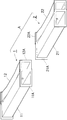
図1は本実施形態の空調ダクトを示す斜視図である。
図1に示すように、本実施形態の空調ダクトAは、一方のダクト1(以下、「前ダクト」という)と、他方のダクト2(以下、「後ダクト」という)とが相互に接合されてなる。
[First embodiment]
An embodiment of the present invention will be described with reference to the drawings.
FIG. 1 is a perspective view showing an air conditioning duct of the present embodiment.
As shown in FIG. 1, in the air conditioning duct A of the present embodiment, one duct 1 (hereinafter referred to as “front duct”) and the other duct 2 (hereinafter referred to as “rear duct”) are joined to each other. It becomes.
前ダクト1は第1単位ダクト(以下、「第1小ダクト」という)11と、第1小ダクト11に並列して添合される第2単位ダクト(以下、「第2小ダクト」という)12と、からなる。そして、第1小ダクト11の開口部は、第2小ダクト12の開口部のよりも大きく形成されている。
The
後ダクト2は第3単位ダクト(以下、「第3小ダクト」という)21と、第3小ダクト21に並列して添合される第4単位ダクト(以下、「第4小ダクト」という)22と、からなる。
このとき、第3小ダクト21の開口部の大きさ及び形状は、対応接合できるように、第1小ダクト11と同一になっており、同様に第4小ダクト22の開口部の大きさ及び形状は、第2小ダクト12と同一となっている。
The
At this time, the size and shape of the opening of the third
また前ダクト1及び後ダクト2の開口部は傾斜して形成されている。
すなわち、第1小ダクト11の開口部は、その長手方向に対して所定の角度で傾斜しており、第2小ダクト12の開口部も同様に、その長手方向に対して所定の角度で傾斜している。
そして第1小ダクト11の開口部の傾斜角度と、第2小ダクトの開口部の傾斜角度とは等しくなっている。
Moreover, the opening part of the
That is, the opening of the first
And the inclination angle of the opening part of the 1st
同様に、第3小ダクト21の開口部及び第4小ダクト22の開口部もそれぞれ、その長手方向に対して所定の角度で傾斜しており、それらの傾斜角度は等しくなっている。
このとき、第3小ダクト21(又は第4小ダクト22)の開口部の傾斜角度は、第1小ダクト11(又は第2小ダクト12)の開口部の傾斜角度と一致している。
Similarly, the opening of the third
At this time, the inclination angle of the opening of the third small duct 21 (or the fourth small duct 22) matches the inclination angle of the opening of the first small duct 11 (or the second small duct 12).
また、第1小ダクト11の開口部周縁及び第2小ダクト12の開口部周縁にはフランジ11A、12Aが形成されており、同様に、第3小ダクト21の開口部周縁及び第4小ダクト22の開口部周縁にもフランジ21A、22Aが形成されている。
Further,
フランジ11A、フランジ12A、フランジ21A、及びフランジ22Aは、通風路の外方へ突出させた外フランジであるため、フランジが通風路内に突出せず、通風路を流れる空調エアの流れはフランジによって乱されない。
Since the
図1に示すように、第1小ダクト11の境界辺に形成されたフランジ11Aと、第2小ダクト12の境界辺に形成されたフランジ12Aとは重なり合って固定されている(このフランジ同士が重なり合った部分を「前重畳フランジ部」という)。
また、第3小ダクト21の境界辺に形成されたフランジ21Aと第4小ダクト22の境界辺に形成されたフランジ22Aも重なり合って固定されている(このフランジ同士が重なり合った部分を「後重畳フランジ部」という)。
As shown in FIG. 1, the
Further, the
図2は本実施形態の空調ダクトの接合方法を示す断面図である。
なお、図2は図1における前ダクト1及び後ダクト2を長手方向に切断し、上方から見た断面図である。
前ダクト1と後ダクト2とを接合した際に、接合部から空調エアが漏れ出すことを防止するために両者間にはシール材3(例えばウレタン製のパッキン)が介在されている。
すなわち、第1小ダクト11及び第2小ダクト12の各フランジ11A、12Aにはシール材3が取り付けられており、同様に第3小ダクト21及び第4小ダクト22の各フランジ21A、22Aにもシール材3が取り付けられている。
シール材が、例えば発泡ポリウレタン製のパッキンである場合は、フランジに接着により貼り付ける方法が採用される。
FIG. 2 is a cross-sectional view showing a method for joining air-conditioning ducts according to this embodiment.
2 is a cross-sectional view of the
When the
That is, the sealing
When the sealing material is, for example, a foamed polyurethane packing, a method of adhering to the flange is adopted.
いま、後ダクト2を前ダクト1に取り付ける際は、図2に矢印で示すように、後ダクト2を前ダクト1の長手方向に垂直な方向から前ダクト1に平行移動させながら近づけて行き、フランジ11Aとフランジ21Aとをシール材3を介して接合し、同時にフランジ12Aとフランジ22Aとをシール材3を介して接合する。
この時、前重畳フランジ部4と後重畳フランジ部5も当然シール材3を介して接合される。ここで、シール材3は各フランジ面により押し潰されて前ダクト1と後ダクト2の接合部分の気密性が向上する。
Now, when attaching the
At this time, the front overlapping
本実施形態の前ダクト1に形成された前重畳フランジ部4及び後ダクト2に形成された後重畳フランジ部5は、共にシール材3を取り付けるにあたり一定の面積を有している。
そのため、本実施形態の前ダクト1と後ろダクト2との間のシール性を確保するのに十分な大きさのシール材3が安定した状態で取り付けられる。
また、前ダクト1と後ダクト2とが多少ズレた状態で偏って接合されたとしても、前重畳フランジ部4及び後重畳フランジ部5は一定の面積を有しているのでエア漏れが生じない。
さらに、各小ダクトの境界辺に突出するフランジが重畳フランジ部として重ね合わされることで、通風路を広くとることができる。
Both the front overlapping
Therefore, the sealing
Further, even if the
Furthermore, the flange which protrudes in the boundary side of each small duct is piled up as a superimposition flange part, and can take a wide ventilation path.
以上により、第1小ダクト11及び第3小ダクト21によって形成される通風路S1と、第2小ダクト12及び第4小ダクト22とにより形成される通風路S2との間で起こるエア漏れ現象が回避されるとともに、接合部分における送風効率の低下が防止される。
As described above, the air leakage phenomenon occurs between the ventilation path S1 formed by the first
ところで、空調ダクト内で生じる圧損の大きさは、空調ダクトの長さに比例し、その断面積の大きさに反比例する。
従って、エアコンが埋設された側のルーフサイドに配設される空調ダクト(以下、「短距離ダクト」という)の断面積と、エアコンが埋設された側とは反対側のルーフサイドに配設される空調ダクト(以下、「長距離ダクト」という)の断面積とが等しい場合、長距離ダクトの方が短距離ダクトよりも長いので、空調エアの吹き出し圧が所定の大きさ以上に設定されなければ、空調を行うのに十分な流速を有する空調エアが長距離ダクトから供給されない。
しかしながら、大きい吹き出し圧でエアコンを稼働させ続けることは、エアコンの寿命を縮める恐れがある。
By the way, the magnitude of the pressure loss generated in the air conditioning duct is proportional to the length of the air conditioning duct and inversely proportional to the size of its cross-sectional area.
Therefore, the cross-sectional area of the air conditioning duct (hereinafter referred to as “short-distance duct”) disposed on the roof side on the side where the air conditioner is embedded and the roof side on the opposite side to the side where the air conditioner is embedded are disposed. If the cross-sectional area of the air-conditioning duct (hereinafter referred to as “long-distance duct”) is equal, the long-distance duct is longer than the short-distance duct, so the blow-off pressure of the air-conditioning air must be set to a predetermined level or more For example, air-conditioning air having a flow rate sufficient for air conditioning is not supplied from the long-distance duct.
However, continuing to operate the air conditioner with a large blowing pressure may shorten the life of the air conditioner.
本実施形態の空調ダクトにおいては、第1小ダクト11及び第3小ダクト21で形成される空調ダクトの断面積(すなわち通風路S1の断面積)は、第2小ダクト12及び第4小ダクト22で形成される空調ダクトの断面積(すなわち通風路S2の断面積)よりも大きい。
従って、第1小ダクト11及び第3小ダクト21で形成される空調ダクトを長距離ダクトとすることで、長距離ダクト内で生ずる圧損の大きさを低減させ、エアコンが埋設された側とは反対側のルーフサイドに適用することができる。
すなわち、空調エアを供給させる際に必要とされる設計吹き出し圧の大きさを低下させることができる。
結果的に、短距離ダクトの断面積と等しい断面積を有する長距離ダクトを用いた場合よりも、エアコンの寿命を延ばすことができる。
In the air conditioning duct of the present embodiment, the sectional area of the air conditioning duct formed by the first
Therefore, by making the air-conditioning duct formed by the first
That is, the magnitude of the design blowing pressure required when supplying the air-conditioned air can be reduced.
As a result, the life of the air conditioner can be extended as compared with the case where a long-distance duct having a cross-sectional area equal to the cross-sectional area of the short-distance duct is used.
[第二の実施形態]
図3は、第二の実施形態の前ダクトと後ダクトとが接合された状態を示す断面図である。
第二の実施形態の空調ダクトAが第一の実施形態の空調ダクトAと異なる点は、図3に示すように、第2小ダクト12の境界辺に形成されたフランジ12A及び第4小ダクト22の境界辺に形成されたフランジ22Aが、通風路側へ突出させた内フランジとなっていることである。
[Second Embodiment]
FIG. 3 is a cross-sectional view showing a state in which the front duct and the rear duct of the second embodiment are joined.
The air conditioning duct A of the second embodiment is different from the air conditioning duct A of the first embodiment in that the
第2小ダクト12の境界辺に形成されるフランジ12Aを内フランジとし、第1小ダクト11の境界辺に形成されるフランジ11Aを外フランジとすることで、第1小ダクト11と第2小ダクト12とを隙間無く添合させることができる。
同様に、第4小ダクトの境界辺に形成されるフランジ22Aを内フランジとし、第3小ダクト21の境界辺に形成されるフランジ21Aを外フランジとすることで、第3小ダクト21と第4小ダクト22とを隙間無く添合させることができる。
By using the
Similarly, the
前ダクト1及び後ダクト2のフランジをこのように形成することで、前ダクト1及び後ダクト2の配設空間が設計上限定されている場合にも、通風路の大きさを極力大きく確保することができる。
そのため、本実施形態の空調ダクトAは、空間的利点に重きを置いた場合に非常に好適である。
なお、本実施形態のフランジ12A及び22Aは通風路S2に突出しているが、その端部は通風路の下流側を向くように設定されているため、空調エアの圧損の悪化が極力低下する。
By forming the flanges of the
Therefore, the air conditioning duct A of the present embodiment is very suitable when emphasizing the spatial advantage.
Incidentally,
以上、本発明を説明してきたが、本発明は実施の形態に限定されることなく種々の変形例が可能である。
例えば、第1小ダクト11とそれに添合する第2小ダクト12とは、別体にして留め具(リベット等)Pで一体に固定することにより取り付けた例で示したが、同体であっても原理的には採用可能である。
その場合、境界辺におけるフランジ11Aとフランジ12A、或いは境界辺におけるフランジ21Aとフランジ22Aは一体となる。
またシール材は、パッキンのようにフランジに一体に取り付けられているものに限らず、ダクトの接合部分を気密に保つためのものであれば別体のものを使用することも可能である。
Although the present invention has been described above, the present invention is not limited to the embodiments, and various modifications can be made.
For example, the first
In that case, the
Further, the sealing material is not limited to the one that is integrally attached to the flange as in the packing, and a separate material may be used as long as it is for keeping the joint portion of the duct airtight.
1・・・前ダクト
11・・・第1小ダクト
11A・・・フランジ
12・・・第2小ダクト
12A・・・フランジ
2・・・後ダクト
21・・・第3小ダクト
21A・・・フランジ
22・・・第4小ダクト
22A・・・フランジ
3・・・シール材
4・・・前重畳フランジ部
5・・・後重畳フランジ部
100・・・単位ダクト
101・・・単位ダクト
102・・・フランジ
300・・・シール材
A・・・空調ダクト
P・・・留め具
S1・・・通風路
S2・・・通風路
T・・・境界壁
DESCRIPTION OF
Claims (4)
一方のダクトは開口部周縁にフランジが形成された第1単位ダクトと、開口部周縁にフランジが形成された第2単位ダクトと、が並列に添合されてなり、
他方のダクトは開口部周縁にフランジが形成された第3単位ダクトと、開口部周縁にフランジが形成された第4単位ダクトと、が並列に添合されてなり、
第1単位ダクト及び第2単位ダクトの開口部は傾斜して形成され、
第3単位ダクト及び第4単位ダクトの開口部は傾斜して形成され、
前記各単位ダクトのフランジが、全て、外フランジとして形成され、且つ、前記開口部の傾斜と同じ傾斜で外方に延びており、
第1単位ダクトの境界辺に形成されたフランジと、第2単位ダクトの境界辺に形成されたフランジとが重なり合って固定され、
第3単位ダクトの境界辺に形成されたフランジと、第4単位ダクトの境界辺に形成されたフランジとが重なり合って固定されることを特徴とする空調ダクト。 An air conditioning duct for a vehicle in which one duct and the other duct are joined to each other,
One duct is formed by joining a first unit duct having a flange formed on the periphery of the opening and a second unit duct having a flange formed on the periphery of the opening in parallel.
The other duct is formed by joining a third unit duct having a flange formed on the periphery of the opening and a fourth unit duct having a flange formed on the periphery of the opening in parallel.
The openings of the first unit duct and the second unit duct are formed to be inclined,
The openings of the third unit duct and the fourth unit duct are formed to be inclined,
The flanges of each unit duct are all formed as outer flanges and extend outward with the same inclination as the inclination of the opening,
The flange formed on the boundary side of the first unit duct and the flange formed on the boundary side of the second unit duct are overlapped and fixed,
An air conditioning duct characterized in that a flange formed on the boundary side of the third unit duct and a flange formed on the boundary side of the fourth unit duct overlap and are fixed.
一方のダクトは開口部周縁にフランジが形成された第1単位ダクトと、開口部周縁にフランジが形成された第2単位ダクトと、が並列に添合されてなり、
他方のダクトは開口部周縁にフランジが形成された第3単位ダクトと、開口部周縁にフランジが形成された第4単位ダクトと、が並列に添合されてなり、
第1単位ダクトの境界辺に形成されたフランジと、第2単位ダクトの境界辺に形成されたフランジとが重なり合って固定され、
第3単位ダクトの境界辺に形成されたフランジと、第4単位ダクトの境界辺に形成されたフランジとが重なり合って固定されるものにおいて、
前記第1単位ダクトの境界辺に形成されたフランジが外フランジであり、
前記第2単位ダクトの境界辺に形成されたフランジが内フランジであり、
前記第3単位ダクトの境界辺に形成されたフランジが外フランジであり、
前記第4単位ダクトの境界辺に形成されたフランジが内フランジである
ことを特徴とする空調ダクト。 An air conditioning duct for a vehicle in which one duct and the other duct are joined to each other,
One duct is formed by joining a first unit duct having a flange formed on the periphery of the opening and a second unit duct having a flange formed on the periphery of the opening in parallel.
The other duct is formed by joining a third unit duct having a flange formed on the periphery of the opening and a fourth unit duct having a flange formed on the periphery of the opening in parallel.
The flange formed on the boundary side of the first unit duct and the flange formed on the boundary side of the second unit duct are overlapped and fixed,
In what the flange formed on the boundary side of the third unit duct and the flange formed on the boundary side of the fourth unit duct are overlapped and fixed,
The flange formed on the boundary side of the first unit duct is an outer flange,
The flange formed on the boundary side of the second unit duct is an inner flange,
The flange formed on the boundary side of the third unit duct is an outer flange,
An air conditioning duct, wherein a flange formed at a boundary side of the fourth unit duct is an inner flange.
前記第3単位ダクトの断面積が前記第4単位ダクトの断面積よりも大きく、
一方のダクトと他方のダクトを接合するときは、第1単位ダクトと第3単位ダクトを接合し、第2単位ダクトと第4単位ダクトとを接合することを特徴とする、請求項1又は2記載の空調ダクト。 A cross-sectional area of the first unit duct is larger than a cross-sectional area of the second unit duct;
A cross-sectional area of the third unit duct is larger than a cross-sectional area of the fourth unit duct;
When joining one duct and the other duct is joined to the first unit duct and the third unit duct, characterized by joining the second unit duct and the fourth unit duct, according to claim 1 or 2 The air conditioning duct described.
Priority Applications (6)
| Application Number | Priority Date | Filing Date | Title |
|---|---|---|---|
| JP2007199957A JP5074852B2 (en) | 2007-07-31 | 2007-07-31 | Air conditioning duct |
| AT08013550T ATE506207T1 (en) | 2007-07-31 | 2008-07-28 | AIR CONDITIONING PIPE |
| DE602008006306T DE602008006306D1 (en) | 2007-07-31 | 2008-07-28 | Air conditioning duct |
| EP08013550A EP2020318B1 (en) | 2007-07-31 | 2008-07-28 | Air-conditioning duct |
| US12/221,189 US8801511B2 (en) | 2007-07-31 | 2008-07-30 | Air-conditioning duct |
| CN2008101448857A CN101357574B (en) | 2007-07-31 | 2008-07-31 | Air-conditioning duct |
Applications Claiming Priority (1)
| Application Number | Priority Date | Filing Date | Title |
|---|---|---|---|
| JP2007199957A JP5074852B2 (en) | 2007-07-31 | 2007-07-31 | Air conditioning duct |
Publications (2)
| Publication Number | Publication Date |
|---|---|
| JP2009035079A JP2009035079A (en) | 2009-02-19 |
| JP5074852B2 true JP5074852B2 (en) | 2012-11-14 |
Family
ID=39797419
Family Applications (1)
| Application Number | Title | Priority Date | Filing Date |
|---|---|---|---|
| JP2007199957A Expired - Fee Related JP5074852B2 (en) | 2007-07-31 | 2007-07-31 | Air conditioning duct |
Country Status (6)
| Country | Link |
|---|---|
| US (1) | US8801511B2 (en) |
| EP (1) | EP2020318B1 (en) |
| JP (1) | JP5074852B2 (en) |
| CN (1) | CN101357574B (en) |
| AT (1) | ATE506207T1 (en) |
| DE (1) | DE602008006306D1 (en) |
Families Citing this family (6)
| Publication number | Priority date | Publication date | Assignee | Title |
|---|---|---|---|---|
| JP5074852B2 (en) * | 2007-07-31 | 2012-11-14 | キョーラク株式会社 | Air conditioning duct |
| GB2497568B (en) * | 2011-12-14 | 2018-01-17 | Polypipe Ltd | Ventilation module and system |
| DE102012204687A1 (en) * | 2012-03-23 | 2013-09-26 | Siemens Aktiengesellschaft | Rail vehicle with air conditioning duct in the roof area and method for building a roof area of a rail vehicle |
| JP6187033B2 (en) * | 2013-08-26 | 2017-08-30 | スズキ株式会社 | Center console structure |
| JP7458038B2 (en) * | 2019-09-04 | 2024-03-29 | 豊和化成株式会社 | Air conditioning duct equipment |
| CN111023322B (en) * | 2019-11-28 | 2021-11-12 | 合肥通用制冷设备有限公司 | Rotatable use type air conditioning device |
Family Cites Families (58)
| Publication number | Priority date | Publication date | Assignee | Title |
|---|---|---|---|---|
| US679932A (en) * | 1900-10-09 | 1901-08-06 | Peter Abrahamson | Ventilator. |
| US1810142A (en) * | 1929-07-20 | 1931-06-16 | Fireproof Wall Company | Conduit coupling collar |
| US1805990A (en) * | 1929-07-20 | 1931-05-19 | Fireproof Wall Company | Conduit assembly |
| US2412071A (en) * | 1944-07-22 | 1946-12-03 | Gen Electric | Cabin supercharging means having automatic pressure and temperature control means |
| US2648348A (en) * | 1947-04-16 | 1953-08-11 | Us Of Atomic Energy Commission | Incineration system |
| US2649742A (en) * | 1948-07-12 | 1953-08-25 | Jacuzzi Bros Inc | Jet pump pipe assembly |
| US2786417A (en) * | 1954-06-17 | 1957-03-26 | Tait Mfg Co The | Pumping system and coupling therefor |
| US3319705A (en) * | 1964-09-29 | 1967-05-16 | Appbau Rothemuhle Brandt & Kri | Rotary regenerative heat exchangers |
| US3336943A (en) * | 1964-11-23 | 1967-08-22 | Ethyl Corp | Multiple pipeline |
| US3693664A (en) * | 1970-10-15 | 1972-09-26 | Hancock Brick & Tile Co | Modular cellular conduit assembly |
| US3693610A (en) * | 1970-12-10 | 1972-09-26 | West Creek Co Inc | Camping stove |
| AR203992A1 (en) * | 1972-04-07 | 1975-11-12 | Berner E | APPARATUS FOR AIR CURTAINS AND CLOSING DOOR WITH APPARATUS FOR AIR CURTAINS |
| US3901275A (en) * | 1974-02-01 | 1975-08-26 | Aeronca Inc | Compact control unit for air distributing systems |
| SE433972B (en) * | 1974-11-01 | 1984-06-25 | Electrolux Ab | DEVICE FOR SUPPLYING FRESH AIR TO AND REMOVING Flue gas from a gas burner |
| NL7512247A (en) * | 1975-10-17 | 1977-04-19 | Ballast Nedam Groep Nv | PISTON. |
| JPS5934831Y2 (en) * | 1979-11-21 | 1984-09-27 | 日産自動車株式会社 | Connection structure of resin duct |
| JPS578973U (en) * | 1980-06-17 | 1982-01-18 | ||
| JPS57101190A (en) * | 1980-12-16 | 1982-06-23 | Kubota Ltd | Attaching flange structure in pipe |
| US5078432A (en) * | 1985-11-27 | 1992-01-07 | The George Ingraham Corporation | Multiple duct conduit and couplings |
| JPH02140553A (en) * | 1988-08-04 | 1990-05-30 | Bullock Mfg Pty Ltd | Air-conditioning duct coupler |
| US5000480A (en) * | 1989-04-27 | 1991-03-19 | Sparkomatic Corporation | Show bar assembly for truck type vehicles |
| US5062354A (en) * | 1990-12-03 | 1991-11-05 | The Marley Company | Side wall vent/air termination unit for boilers |
| JP3137728B2 (en) * | 1992-04-06 | 2001-02-26 | 三喜工業株式会社 | Method of manufacturing flexible joint for duct and flexible joint for duct |
| US5312524A (en) * | 1992-04-21 | 1994-05-17 | Filter Tech, Inc. | Distillation system for recovery of industrial process liquids |
| US5282456A (en) * | 1992-06-17 | 1994-02-01 | Rheem Manufacturing Company | High efficiency fuel fired induced draft condensing furnace with horizontal plastic vent termination assembly |
| JPH06106956A (en) | 1992-09-30 | 1994-04-19 | Suzuki Motor Corp | Connecting part structure of air conditioning duct for automobile |
| JP2758798B2 (en) * | 1992-11-19 | 1998-05-28 | 株式会社オーバル | Coriolis flow meter |
| US5444947A (en) * | 1993-02-09 | 1995-08-29 | Noll Manufacturing Co. | Foundation vent |
| JPH06234319A (en) * | 1993-02-12 | 1994-08-23 | Suzuki Motor Corp | Duct connecting structure for side ventilator |
| JP3413937B2 (en) * | 1994-03-28 | 2003-06-09 | 株式会社デンソー | Piping connection device |
| JP3530608B2 (en) * | 1994-12-20 | 2004-05-24 | 高砂熱学工業株式会社 | Air conditioning and smoke exhaust ducts |
| NO311992B1 (en) * | 1995-10-26 | 2002-02-25 | Hystad Anne Elise | Device for leak detection by pressure testing of flange joints on the ends of pipelines included in the piping system |
| US5904896A (en) * | 1995-12-08 | 1999-05-18 | A. R. Grindl | Multi-stage zonal air purification system |
| JP3250458B2 (en) * | 1996-05-31 | 2002-01-28 | トヨタ自動車株式会社 | Exhaust pipe connection structure of internal combustion engine |
| JPH1089058A (en) * | 1996-09-18 | 1998-04-07 | Toyota Motor Corp | Flange assembly and its manufacture |
| JP3296479B2 (en) * | 1997-05-29 | 2002-07-02 | トヨタ車体株式会社 | Duct fixing structure |
| IT248048Y1 (en) * | 1999-02-22 | 2002-12-09 | Raco S P A | COUPLING JOINT PERFECTED FOR A PAIR OF PIPES |
| JP3426549B2 (en) * | 1999-11-12 | 2003-07-14 | 本田技研工業株式会社 | Exhaust pipe connection structure |
| CA2349332A1 (en) * | 2001-05-31 | 2002-11-30 | Martin Gamelin | Exterior inlet/exhaust port |
| JP2003034115A (en) * | 2001-07-23 | 2003-02-04 | Mitsubishi Heavy Ind Ltd | Automotive air-conditioning duct |
| JP2004034832A (en) * | 2002-07-03 | 2004-02-05 | Gp Daikyo Corp | Structure of outside air inlet duct for vehicle |
| JP2004249826A (en) * | 2003-02-20 | 2004-09-09 | Hino Motors Ltd | Air conditioning duct structure of vehicle |
| JP2004257597A (en) * | 2003-02-24 | 2004-09-16 | Howa Kasei Kk | Bent duct and method of manufacturing bent duct |
| DE102004036719A1 (en) * | 2003-08-07 | 2005-03-17 | Denso Corp., Kariya | Pipe connection construction and manufacturing method therefor |
| JP2005335628A (en) * | 2004-05-28 | 2005-12-08 | Toyoda Gosei Co Ltd | Air-conditioning duct for vehicle, and its mounting method |
| DE102004046058A1 (en) * | 2004-09-21 | 2006-03-23 | Behr Gmbh & Co. Kg | Connection of two air-conducting components of a ventilation system, in particular a motor vehicle ventilation system |
| CN2774833Y (en) * | 2004-11-27 | 2006-04-26 | 肖利华 | Internal air exchanger for automobile |
| US20080318514A1 (en) * | 2005-02-08 | 2008-12-25 | Fettkether, Llc | Plastic hvac component system and method for installing the same |
| JP2006219024A (en) * | 2005-02-10 | 2006-08-24 | Denso Corp | Duct connection structure of vehicular air-conditioner |
| CN2866215Y (en) * | 2005-12-20 | 2007-02-07 | 比亚迪股份有限公司 | Vehicle air conditioner rotary throttle sealing device |
| US7517280B2 (en) * | 2006-02-07 | 2009-04-14 | Toyota Motor Engineering & Manufacturing North America, Inc. | Air duct assembly for a vehicle |
| JP4943266B2 (en) * | 2007-07-31 | 2012-05-30 | キョーラク株式会社 | Mounting structure of air conditioning unit and air conditioning duct |
| JP5074852B2 (en) * | 2007-07-31 | 2012-11-14 | キョーラク株式会社 | Air conditioning duct |
| DE202007012988U1 (en) * | 2007-09-17 | 2009-02-12 | Carcoustics Techconsult Gmbh | Multi-channel air guiding device |
| US20090083962A1 (en) * | 2007-09-27 | 2009-04-02 | Langdon Incorporated | Flange-forming system for tube and related methods |
| KR101481694B1 (en) * | 2008-07-08 | 2015-01-12 | 한라비스테온공조 주식회사 | Air conditioner for vehicles |
| US20100112928A1 (en) * | 2008-11-03 | 2010-05-06 | Airex Inc. | Adaptable exhaust box |
| DE102009031253A1 (en) * | 2009-07-01 | 2011-01-05 | Dr. Ing. H.C. F. Porsche Aktiengesellschaft | motor vehicle |
-
2007
- 2007-07-31 JP JP2007199957A patent/JP5074852B2/en not_active Expired - Fee Related
-
2008
- 2008-07-28 DE DE602008006306T patent/DE602008006306D1/en active Active
- 2008-07-28 EP EP08013550A patent/EP2020318B1/en not_active Not-in-force
- 2008-07-28 AT AT08013550T patent/ATE506207T1/en not_active IP Right Cessation
- 2008-07-30 US US12/221,189 patent/US8801511B2/en active Active
- 2008-07-31 CN CN2008101448857A patent/CN101357574B/en not_active Expired - Fee Related
Also Published As
| Publication number | Publication date |
|---|---|
| EP2020318A2 (en) | 2009-02-04 |
| DE602008006306D1 (en) | 2011-06-01 |
| CN101357574A (en) | 2009-02-04 |
| US20090042503A1 (en) | 2009-02-12 |
| CN101357574B (en) | 2012-06-27 |
| ATE506207T1 (en) | 2011-05-15 |
| EP2020318B1 (en) | 2011-04-20 |
| EP2020318A3 (en) | 2010-06-23 |
| US8801511B2 (en) | 2014-08-12 |
| JP2009035079A (en) | 2009-02-19 |
Similar Documents
| Publication | Publication Date | Title |
|---|---|---|
| JP5074852B2 (en) | Air conditioning duct | |
| US10556602B2 (en) | Car air conditioning duct and railcar | |
| US9205721B2 (en) | Cross-car structural support with integrated HVAC floor duct | |
| JP2007147269A (en) | Duct and its manufacturing method | |
| CN104417315B (en) | Center armrest box structure | |
| WO2017164189A1 (en) | Vehicle roof structure | |
| US20140073232A1 (en) | Laterally Assembled Vehicle Duct Joint | |
| US10766339B2 (en) | Vehicle structural air duct | |
| JP4943266B2 (en) | Mounting structure of air conditioning unit and air conditioning duct | |
| JP4732415B2 (en) | Vehicle air conditioner | |
| JP6890048B2 (en) | Railroad vehicle | |
| US11214316B2 (en) | Vehicle body lower part structure | |
| JP4943245B2 (en) | Ceiling unit for railway vehicles | |
| JP6546470B2 (en) | Air conditioning duct connection structure | |
| JP2006264440A (en) | Heater duct structure for vehicle | |
| JP4677881B2 (en) | Vehicle floor structure | |
| JP5498076B2 (en) | Vehicle panel structure | |
| JP4774938B2 (en) | Vehicle cowl box structure | |
| JP2009056893A (en) | Rear door of vehicle | |
| JP2008105465A (en) | Vent duct fixing structure | |
| JP4001036B2 (en) | Vehicle cooler duct structure | |
| JP2011093499A (en) | Instrument panel structure | |
| JP2011156973A (en) | Air-conditioning duct structure for vehicle | |
| JP2007210508A (en) | Junction structure for air duct | |
| JP5056424B2 (en) | Air conditioning duct |
Legal Events
| Date | Code | Title | Description |
|---|---|---|---|
| A621 | Written request for application examination |
Free format text: JAPANESE INTERMEDIATE CODE: A621 Effective date: 20100629 |
|
| A711 | Notification of change in applicant |
Free format text: JAPANESE INTERMEDIATE CODE: A711 Effective date: 20100907 |
|
| A521 | Request for written amendment filed |
Free format text: JAPANESE INTERMEDIATE CODE: A821 Effective date: 20100908 |
|
| A521 | Request for written amendment filed |
Free format text: JAPANESE INTERMEDIATE CODE: A523 Effective date: 20101018 |
|
| A521 | Request for written amendment filed |
Free format text: JAPANESE INTERMEDIATE CODE: A821 Effective date: 20101019 |
|
| A977 | Report on retrieval |
Free format text: JAPANESE INTERMEDIATE CODE: A971007 Effective date: 20120126 |
|
| A131 | Notification of reasons for refusal |
Free format text: JAPANESE INTERMEDIATE CODE: A131 Effective date: 20120203 |
|
| A521 | Request for written amendment filed |
Free format text: JAPANESE INTERMEDIATE CODE: A523 Effective date: 20120328 |
|
| TRDD | Decision of grant or rejection written | ||
| A01 | Written decision to grant a patent or to grant a registration (utility model) |
Free format text: JAPANESE INTERMEDIATE CODE: A01 Effective date: 20120806 |
|
| A01 | Written decision to grant a patent or to grant a registration (utility model) |
Free format text: JAPANESE INTERMEDIATE CODE: A01 |
|
| A61 | First payment of annual fees (during grant procedure) |
Free format text: JAPANESE INTERMEDIATE CODE: A61 Effective date: 20120824 |
|
| R150 | Certificate of patent or registration of utility model |
Ref document number: 5074852 Country of ref document: JP Free format text: JAPANESE INTERMEDIATE CODE: R150 Free format text: JAPANESE INTERMEDIATE CODE: R150 |
|
| FPAY | Renewal fee payment (event date is renewal date of database) |
Free format text: PAYMENT UNTIL: 20150831 Year of fee payment: 3 |
|
| R250 | Receipt of annual fees |
Free format text: JAPANESE INTERMEDIATE CODE: R250 |
|
| S111 | Request for change of ownership or part of ownership |
Free format text: JAPANESE INTERMEDIATE CODE: R313117 |
|
| R350 | Written notification of registration of transfer |
Free format text: JAPANESE INTERMEDIATE CODE: R350 |
|
| R250 | Receipt of annual fees |
Free format text: JAPANESE INTERMEDIATE CODE: R250 |
|
| R250 | Receipt of annual fees |
Free format text: JAPANESE INTERMEDIATE CODE: R250 |
|
| R250 | Receipt of annual fees |
Free format text: JAPANESE INTERMEDIATE CODE: R250 |
|
| R250 | Receipt of annual fees |
Free format text: JAPANESE INTERMEDIATE CODE: R250 |
|
| R250 | Receipt of annual fees |
Free format text: JAPANESE INTERMEDIATE CODE: R250 |
|
| R250 | Receipt of annual fees |
Free format text: JAPANESE INTERMEDIATE CODE: R250 |
|
| LAPS | Cancellation because of no payment of annual fees |