JP2004257597A - Bent duct and method of manufacturing bent duct - Google Patents
Bent duct and method of manufacturing bent duct Download PDFInfo
- Publication number
- JP2004257597A JP2004257597A JP2003046445A JP2003046445A JP2004257597A JP 2004257597 A JP2004257597 A JP 2004257597A JP 2003046445 A JP2003046445 A JP 2003046445A JP 2003046445 A JP2003046445 A JP 2003046445A JP 2004257597 A JP2004257597 A JP 2004257597A
- Authority
- JP
- Japan
- Prior art keywords
- bent
- bent duct
- duct
- outlet
- inlet
- Prior art date
- Legal status (The legal status is an assumption and is not a legal conclusion. Google has not performed a legal analysis and makes no representation as to the accuracy of the status listed.)
- Pending
Links
Images


Abstract
Description
【0001】
【発明の属する技術分野】
本発明は、入口部、と出口部、との間で曲折部を形成し、流体が流れる曲折ダクトに関するものである。
【0002】
【従来の技術】
従来より、例えば、自動車の車内空調に用いる空調機からの曲折部を有する通風ダクト(以下、「曲折ダクト」と記す)は、曲折部にて通風が不均一となり偏流や風音が発生するために、その低減目的で曲折部には分離板を設けている。そして、この分離板により、空調機から送られる通風は、前記曲折部にて発生する不均一が改善されるため、吹出口(例えば、レジスタ)からの通風は、偏流が減少し、且つ風音も少なくなり、乗員に快適な車内空間をもたらしている。
例えば、前記曲折ダクトには、主に以下に示す形状の1つが用いられており、図10〜図12を参照して説明する。
(1)まず、図10に示す曲折ダクト30について説明する。図10(a)は、断面四角状の曲折ダクトの斜視図、図10(b)は、A〜A断面図である。
曲折ダクト30の曲折部の中央には、流路方向に曲折して、側壁から他の側壁に向かって断面径の略半分まで突出している凸部を一体形成の分離板31が形成してある。この分離板31により、断面径の略半分は、上流路35と下流路36に分流されて流体は流れるようになっている。この曲折ダクト30の形状を、以下「a形状」として説明する。
(2)次に、図11に示す曲折ダクト40について説明する。図11(a)は、断面四角状の曲折ダクトの斜視図、図11(b)は、B〜B断面図である。
曲折ダクト40の曲折部の中央には、流路方向に曲折して、一方の側壁に三日月状の挿入孔43が形成してある。また、分離板41は、前記挿入孔43から挿入可能でダクト口径の略半分に至る長さの三日月状の分離板41と、この分離板41の端部に設けてあるフランジ44で構成してある。そして、この分離板41を前記挿入孔43から挿入すると、断面径の略半分は、上流路45と下流路46に分流されて流体は流れるようになっている。この曲折ダクト40の形状を、以下「b形状」として説明する。
(3)さらに、図12に示す曲折ダクト50について説明する。図12(a)は、断面四角状の曲折ダクトの斜視図、図12(b)は、C〜C断面図である。
曲折ダクト50は、流路方向に対して対称となるように予め2分割された曲折ダクト部材50a、50bを組み付ける構成であり、曲折部の中央には、流路方向に曲折して、一方の曲折ダクト部材50bの側壁の内面から他方の曲折ダクト部材50aの側壁の内面に向って断面径の略半分まで突出している凸部を一体形成している分離板51が形成してある。この分離板51により、断面径の略半分は、上流路55と下流路56に分流されて流体は流れるようになっている。この曲折ダクト50の形状を、以下「c形状」として説明する。
このように、上記(1)〜(3)に記した曲折ダクト30、40,50は、曲折部における、曲折部の略半分のみが分離板31、41、51により上流路35、45、55及び下流路36、46、56に分別されており、前記分離板31、41、51を設けていない曲折ダクト(図、符号なし)と比較して前記曲折部で発生する通風の不均一が改善されている。なお、前記分離板31、41、51は、断面径の略半分まで突出している例を示したが、断面径を横断するまで突出していても同様に通風の不均一が改善されている。
【0003】
なお、上記に説明した(1)〜(3)の曲折ダクト30、40、50の形状は、従来より一般的であるので、あえて先行技術文献を記載しない。
【0004】
【発明が解決しようとする課題】
しかしながら、従来の曲折ダクト30、40、50の形状では、以下に示す課題が挙げられる。
(1)上述した「a形状」では、分離板31は、曲折ダクト30の側壁の外面を押圧して形成するため、前記分離板31が厚くなりすぎ(図10(b)参照)、通風時の圧損、風音も低減されているが、未だ十分でない。
(2)上述した「b形状」では、挿入孔43は、フランジ44にて閉塞されるが、通風漏れの懸念がある。また、挿込孔43を形成する穿設工程を要し、曲折ダクト40の製造工程の工数増となる。また、通風時の圧損、風音も低減されているが、未だ十分でない。
(3)上述した「c形状」では、曲折ダクト部材50a、50bの組付工程(例えば、溶着等)を要し、且つ、その組付箇所からの通風漏れのないように密着性も要求され曲折ダクト50の製造工程の工数増となり、また、通風時の圧損、風音も低減されているが、未だ十分でない。
本発明は、このような点に鑑みて創案されたものであり、入口部と、出口部との間で曲折部を形成の曲折ダクトにおいて、通風時の圧損が少なく、その出口部で風音が少なくなる分離板を簡便に形成可能な曲折ダクトを提供することを課題とする。
【0005】
【課題を解決するための手段】
上記課題を解決するための手段として、本発明の第1発明は、請求項1に記載されたとおりの曲折ダクトである。
請求項1に記載の曲折ダクトを用いれば、入口部から出口部に到って、曲折ダクトの内部に複数の通路を形成可能な分離体を取付けることにより、簡便に、通風時の圧損、及び出口部での風音を低減できる。
【0006】
本発明の第2発明は、請求項2に記載されたとおりの曲折ダクトである。
請求項2に記載の曲折ダクトを用いれば、入口部、及び出口部、それぞれに切欠部を有し、前記分離体の一部を前記切欠部に嵌合して固定することができる。
これにより、分離体の一部をそれぞれ入口部、及び出口部の切欠部に嵌合してその位置で固定できるために、曲折ダクトの内部から分離体が外れたり、ずれたりしない構成となる。
【0007】
本発明の第3発明は、請求項3に記載されたとおりの曲折ダクトの製造方法である。
請求項3に記載の曲折ダクトの製造方法であれば、曲折ダクトを製作する工程と、分離体を製作する工程とを備えている。これにより、前記製作した曲折ダクトの入口部、もしくは出口部の一方から、前記製作した分離体を挿入できる。これにより、前記曲折ダクト内に簡便に前記分離体を取付ける曲折ダクトが製造可能である。
【0008】
【発明の実施の形態】
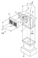
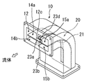
本発明の実施の形態を図面を用いて説明する。図1は、本発明の曲折ダクト10を自動車の室内空調に用いる空調機60からの通風ダクトに適用した一実施の形態の全体斜視図を示している。また、通常、曲折ダクト10の形状は、円筒状、角筒状等、種々のタイプがあるが、本実施の形態では角筒状のものを例に説明する。
【0009】
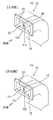
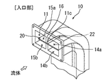
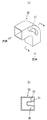
図2(a)、図2(b)を参照して入口部11、と出口部12、との間で曲折部を有し、流体が流れる曲折ダクト10について説明する。この曲折ダクト10には、入口部11と出口部12が、90度の位置変更し、断面方形状の流路が形成してある。前記流路は、同じ開口となるように仕切壁16が設けてあり、右流路14と左流路15に分流する。また、入口部11、出口部12にはフランジ11a、12aが取り付けてあり、入口部11は空調機60と、出口部12は吹出口61と前記フランジ11a、12aを介してボルト17で接続する。また、前記仕切壁16の入口部11と出口部12には、後述する分離体20に形成のスリット22の端部、及びバンド23aの断面形状が嵌合する凹形状の入口切欠部11c、及び出口切欠部12cが形成している。
【0010】
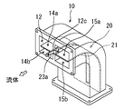
次に、図3を参照して、曲折ダクト10に挿入する分離体20について説明する。この分離体20は、長方形の薄板を、前記曲折ダクト10の右流路14と左流路15をそれぞれ上流路と下流路に分流可能に曲がり形状に合うように曲折してあると共に、中央部には、前記仕切壁16に嵌合可能な他端部が閉口、端部が開口のスリット22が形成してある。なお、この分離体20を曲折ダクト10に挿入することによって、前記曲折ダクト10内の流路を上下同じ高さに分流され、右上流路14a、左上流路15a、右下流路14b、左下流路15bが形成される。また、スリット22の出口部12の両端部には、板状の固定体23c、23eが取り付けてある。そして、一方の固定体23cには、端部に開口部23bを形成の曲折可能で柔軟なバンド23aが固定してあり、他方の固定体23eの外側(反スリット側)には、前記バンド23aの開口部23bを嵌合するバンド凸部23dが形成してある。
【0011】
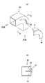
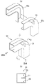
次に、図4〜図8を参照して、前記分離体20を曲折ダクト10の内部に挿入して組み立てる方法について説明する。予め、曲折ダクト10、及び分離体20をそれぞれ別工程で製作しておく。まず、図4に記すように、前記分離体20のバンド23aを有する側を、曲折ダクト10の入口部11から内部に挿入し、スリット22を仕切壁16に嵌合させながら出口部12側に押し込んで、図5に記すように、スリット22の端部と入口切欠部11cの端部を嵌合させる。次に、この嵌合を維持した状態で、図6〜図8に記すように出口部12から現れた分離体20のバンド23aを把持して、分離板21を曲折ダクト10に沿わせ、バンド23aと出口切欠部12cが嵌合可能になるように位置合わせをした後に、バンド23aに形成のバンド開口部23bをバンド凸部23dに嵌合して分離体20を曲折ダクト10の内部に支持、固定する。
以上のように、曲折ダクト10と別構成の分離体20は、前記曲折ダクト10の内部に簡便に支持、固定できる。
【0012】
また、上述したように前記分離体20と前記曲折ダクト10をそれぞれ別工程で製作しておき、その後、前記分離体20を前記曲折ダクト10の内部に挿入して組み立てるため、複数枚の分離体20の挿入が可能となり、また、分離体20の分離板21の形状も、簡便に変更可能である。
【0013】
次に、本実施の形態の曲折ダクト10と、従来の曲折ダクト30との風音、圧損の比較実験の結果を表1に示す。
【0014】
【表1】

【0015】
また、図9に記すように、曲折ダクト10が3次元的に曲折している場合でも、内部に挿入する分離体20の分離板21を、その曲折ダクト10の曲折に対応可能に捩じれ形状に構成可能である。
【0016】
なお、本実施の形態で説明した分離体20の分離板21は、予め曲折ダクト10の曲折に対応可能に曲げた形状で製作する例を説明したが、これに限られるものではなく、製作時には、曲折していない平板形状で、曲折ダクト10に挿入時に前記平板を曲げて挿入する曲折可能部材で製作しても良い。
なお、本実施の形態で説明した分離体20は、必要に応じて分離板21のサイズ、例えば、分離板21の幅を変更することが可能である。そして、分離板21の枚数や、設置位置は、曲折ダクト10の断面形状や曲がり具合に応じて適宜に設定し得る。
なお、本実施の形態で説明した曲折ダクト10には、右流路14、左流路15と2流路に分流する仕切壁16を形成している曲折ダクト10の例を説明したが、これに限定されるものでなく、例えば、曲折ダクト10の内部には、仕切壁16が形成していなくても良いし、3流路以上に分流する複数の仕切壁16が形成していても良い。
なお、本実施の形態で説明した曲折ダクト10は、空調機60と、吹出口61と、をボルト17で接続する構成を例示したが、これに限られるものでなく、例えば、ウレタンシール(図、符号なし)で接続する構成でも良い。その場合には、例えば、空調機60の出口部が曲折ダクト10のフランジ11aに嵌合可能な構成である。そして空調機60の出口部の全周にシール材(例えば、ウレタンシール)を巻き付けておき、曲折ダクト10のフランジ11aに前記シール材を巻き付けた前記空調機60の出口部を嵌合して接続する構成とする。また、吹出口61の入口部と曲折ダクト10のフランジ12aも同様な構成とするため説明は省略する。
【0017】
【発明の効果】
以上説明したように、請求項1〜2のいずれかに記載の曲折ダクト10を用いれば、通風時の圧損が少なく、その出口部12で風音が少なく、且つ簡便に分離板21を形成可能な曲折ダクト10を提供することができる。また、請求項3に記載の曲折ダクトの製造方法を用いれば、通風時の圧損が少なく、その出口部12で風音が少なく、且つ簡便に分離板21を形成可能な曲折ダクト10を製造することができる。
【図面の簡単な説明】
【図1】本発明の曲折ダクト10を、自動車の室内空調に用いる空調機からの通風曲折ダクトに適用した一実施の形態の全体斜視図である。
【図2】(a)曲折ダクト10の入口部11、及び(b)曲折ダクト10の出口部12について説明する図である。
【図3】分離体20について説明する図である。
【図4】分離体20を曲折ダクト10に挿入する前の状態について説明する図である。
【図5】分離体20を曲折ダクト10に挿入した後の入口部11について説明する図である。
【図6】分離体20を曲折ダクト10に挿入した後の出口部12でバンド23aを曲げていない状態について説明する図である。
【図7】分離体20を曲折ダクト10に挿入した後の出口部12でバンド23aをL字形状(90度)に曲げた状態について説明する図である。
【図8】分離体20を曲折ダクト10に挿入した後の出口部12でバンド23aをU字形状(180度)に曲げた状態について説明する図である。
【図9】3次元的に曲折している曲折ダクト10の内部に、分離板21を挿入した状態について説明する図である。
【図10】従来の、「a形状」の曲折ダクト30の斜視図(a)、及び前記(a)のA〜A線断面図(b)について説明する図である。
【図11】従来の、「b形状」の曲折ダクト40の斜視図(a)、及び前記(a)のB〜B線断面図(b)について説明する図である。
【図12】従来の、「c形状」の曲折ダクト50の斜視図(a)、及び前記(a)のC〜C線断面図(b)について説明する図である。
【符号の説明】
10 曲折ダクト
11 入口部
12 出口部
20 分離体
21 分離板[0001]
TECHNICAL FIELD OF THE INVENTION
TECHNICAL FIELD The present invention relates to a bent duct in which a bent portion is formed between an inlet portion and an outlet portion, and through which a fluid flows.
[0002]
[Prior art]
Conventionally, for example, a ventilation duct having a bent portion from an air conditioner used for air conditioning in a vehicle (hereinafter, referred to as a “bent duct”) has a non-uniform ventilation at the bent portion and generates drift and wind noise. In addition, a separating plate is provided at the bent portion for the purpose of reducing the number of the bent portions. The separation plate reduces the unevenness of the air sent from the air conditioner at the bent portion, so that the air flow from the outlet (for example, a register) reduces the drift and reduces the wind noise. And the passengers have a comfortable interior space.
For example, one of the following shapes is mainly used for the bent duct, which will be described with reference to FIGS.
(1) First, the
At the center of the bent portion of the
(2) Next, the
In the center of the bent portion of the
(3) Further, the
The
As described above, in the
[0003]
Note that the shapes of the
[0004]
[Problems to be solved by the invention]
However, the
(1) In the “a shape” described above, since the
(2) In the “b shape” described above, the
(3) The above-mentioned "c-shape" requires an assembling step (for example, welding or the like) of the
The present invention has been made in view of such a point, and in a bent duct having a bent portion formed between an inlet portion and an outlet portion, pressure loss at the time of ventilation is small, and wind noise is generated at the outlet portion. It is an object of the present invention to provide a bent duct that can easily form a separation plate with reduced number.
[0005]
[Means for Solving the Problems]
As a means for solving the above problems, a first invention of the present invention is a bent duct as described in claim 1.
When the bent duct according to claim 1 is used, a separator capable of forming a plurality of passages is installed inside the bent duct from the inlet to the outlet, so that pressure loss during ventilation can be easily achieved, and Wind noise at the exit can be reduced.
[0006]
A second aspect of the present invention is a bent duct as described in claim 2.
If the bent duct according to claim 2 is used, a cutout portion is provided at each of the inlet portion and the outlet portion, and a part of the separation body can be fitted and fixed to the cutout portion.
Accordingly, since a part of the separator can be fitted into the cutouts of the inlet and the outlet, respectively, and fixed at that position, the separator does not come off or deviate from the inside of the bent duct.
[0007]
A third invention of the present invention is a method for manufacturing a bent duct as described in claim 3.
According to a third aspect of the present invention, there is provided a method of manufacturing a bent duct, comprising the steps of manufacturing a bent duct and manufacturing a separator. Thus, the manufactured separator can be inserted from one of the entrance and the exit of the manufactured bent duct. This makes it possible to manufacture a bent duct in which the separator is easily mounted in the bent duct.
[0008]
BEST MODE FOR CARRYING OUT THE INVENTION
An embodiment of the present invention will be described with reference to the drawings. FIG. 1 is an overall perspective view of an embodiment in which a
[0009]
With reference to FIGS. 2A and 2B, a description will be given of a
[0010]
Next, the
[0011]
Next, a method of inserting the
As described above, the separated
[0012]
In addition, as described above, the
[0013]
Next, Table 1 shows the results of a comparison experiment of wind noise and pressure loss between the
[0014]
[Table 1]
[0015]
Also, as shown in FIG. 9, even when the
[0016]
In addition, although the example in which the
In the
In the meantime, in the
In the meantime, the
[0017]
【The invention's effect】
As described above, if the
[Brief description of the drawings]
FIG. 1 is an overall perspective view of an embodiment in which a
FIGS. 2A and 2B are diagrams illustrating an
FIG. 3 is a diagram illustrating a
FIG. 4 is a diagram illustrating a state before a
FIG. 5 is a diagram illustrating an
FIG. 6 is a diagram illustrating a state in which the
FIG. 7 is a diagram illustrating a state in which the
FIG. 8 is a diagram illustrating a state in which the
FIG. 9 is a diagram illustrating a state in which a separating
FIG. 10 is a diagram illustrating a perspective view (a) of a conventional “a-shaped”
FIG. 11 is a diagram illustrating a perspective view (a) of a conventional “b-shaped”
FIG. 12 is a diagram illustrating a perspective view (a) of a conventional “c-shaped”
[Explanation of symbols]
DESCRIPTION OF
Claims (3)
前記入口部から前記出口部に到って、前記曲折ダクトに複数の通路を形成可能な分離体を取付ける、
ことを特徴とする曲折ダクト。A bent duct forming a bent portion between an inlet portion and an outlet portion,
Attaching the separator capable of forming a plurality of passages in the bent duct, from the inlet to the outlet.
A bent duct characterized by the fact that:
前記入口部、及び前記出口部、それぞれに切欠部を有し、
前記分離体の一部を前記切欠部に嵌合して固定する、
ことを特徴とする曲折ダクト。The bent duct according to claim 1,
The inlet portion, and the outlet portion, each has a notch,
A part of the separation body is fitted and fixed in the notch,
A bent duct characterized by the fact that:
曲折ダクトを製作する工程と、分離体を製作する工程と、を備えており、
前記製作した曲折ダクトの入口部、もしくは出口部の一方から、前記分離体を挿入して、前記曲折ダクト内に取付ける、
ことを特徴とする曲折ダクトの製造方法。The bent duct according to any one of claims 1 and 2,
A step of manufacturing a bent duct and a step of manufacturing a separation body,
From one of the entrance portion or the exit portion of the manufactured bent duct, insert the separation body and attach the inside of the bent duct,
A method for manufacturing a bent duct.
Priority Applications (1)
| Application Number | Priority Date | Filing Date | Title |
|---|---|---|---|
| JP2003046445A JP2004257597A (en) | 2003-02-24 | 2003-02-24 | Bent duct and method of manufacturing bent duct |
Applications Claiming Priority (1)
| Application Number | Priority Date | Filing Date | Title |
|---|---|---|---|
| JP2003046445A JP2004257597A (en) | 2003-02-24 | 2003-02-24 | Bent duct and method of manufacturing bent duct |
Publications (1)
| Publication Number | Publication Date |
|---|---|
| JP2004257597A true JP2004257597A (en) | 2004-09-16 |
Family
ID=33112986
Family Applications (1)
| Application Number | Title | Priority Date | Filing Date |
|---|---|---|---|
| JP2003046445A Pending JP2004257597A (en) | 2003-02-24 | 2003-02-24 | Bent duct and method of manufacturing bent duct |
Country Status (1)
| Country | Link |
|---|---|
| JP (1) | JP2004257597A (en) |
Cited By (6)
| Publication number | Priority date | Publication date | Assignee | Title |
|---|---|---|---|---|
| JP2007246034A (en) * | 2006-03-17 | 2007-09-27 | Inoac Corp | Connecting duct member |
| JP2009035079A (en) * | 2007-07-31 | 2009-02-19 | Kyoraku Co Ltd | Air conditioning duct |
| JP2015187522A (en) * | 2014-03-27 | 2015-10-29 | 株式会社富士通ゼネラル | Duct air conditioner |
| CN106091214A (en) * | 2016-05-27 | 2016-11-09 | 袁长勃 | A kind of forced draft actinal surface plate and processing method thereof |
| CN109311490A (en) * | 2016-06-03 | 2019-02-05 | 川崎重工业株式会社 | Rolling stock air-conditioning duct |
| JP2019035533A (en) * | 2017-08-11 | 2019-03-07 | 新東工業株式会社 | Push hood device |
-
2003
- 2003-02-24 JP JP2003046445A patent/JP2004257597A/en active Pending
Cited By (7)
| Publication number | Priority date | Publication date | Assignee | Title |
|---|---|---|---|---|
| JP2007246034A (en) * | 2006-03-17 | 2007-09-27 | Inoac Corp | Connecting duct member |
| JP2009035079A (en) * | 2007-07-31 | 2009-02-19 | Kyoraku Co Ltd | Air conditioning duct |
| JP2015187522A (en) * | 2014-03-27 | 2015-10-29 | 株式会社富士通ゼネラル | Duct air conditioner |
| CN106091214A (en) * | 2016-05-27 | 2016-11-09 | 袁长勃 | A kind of forced draft actinal surface plate and processing method thereof |
| CN109311490A (en) * | 2016-06-03 | 2019-02-05 | 川崎重工业株式会社 | Rolling stock air-conditioning duct |
| CN109311490B (en) * | 2016-06-03 | 2020-07-10 | 川崎重工业株式会社 | Air conditioning pipeline for railway vehicle |
| JP2019035533A (en) * | 2017-08-11 | 2019-03-07 | 新東工業株式会社 | Push hood device |
Similar Documents
| Publication | Publication Date | Title |
|---|---|---|
| JP4540468B2 (en) | Vehicle cowl structure with vent pipe | |
| JP5290490B2 (en) | Heating, ventilation and air conditioning equipment for vehicles | |
| JP2006051944A (en) | Front passenger seat airbag module | |
| CN106247476A (en) | Portable air actuator | |
| JP2004257597A (en) | Bent duct and method of manufacturing bent duct | |
| CN104093990A (en) | Sound-proofing housing for a respirator | |
| JPH11280479A (en) | Intercooler | |
| JP2011148482A (en) | Filter assembly for vehicle heating or air conditioning system, filter unit for the same, and method of manufacturing filter assembly | |
| JP2009248866A (en) | Intake duct for vehicle air conditioning and air conditioner for vehicle | |
| JPH10203150A (en) | Sealing device for heat exchanger | |
| US8783413B1 (en) | Tuned shunt tubes for climate control air-handling systems | |
| JP4943266B2 (en) | Mounting structure of air conditioning unit and air conditioning duct | |
| EP3193097A1 (en) | Indoor unit for air conditioner | |
| JP2013180646A (en) | Vehicle air conditioner | |
| JP2001026213A (en) | Expansion valve and air conditioner unit for vehicle using the same | |
| JP2011521827A (en) | Airbag module | |
| EP3073076A1 (en) | Muffler | |
| JP2006317099A (en) | Air conditioner | |
| JP2009056870A (en) | Air-conditioning duct structure for automobile | |
| CN108119216B (en) | Exhaust muffler and method of manufacturing the same | |
| JP2007331532A (en) | Pipe seal packing of vehicle air conditioner | |
| WO2011096224A1 (en) | Air conditioning device for vehicle | |
| WO2017141514A1 (en) | Air conditioner unit for vehicle | |
| JPH10305723A (en) | Air conditioner for vehicle | |
| JP5573492B2 (en) | Installation structure of automobile air conditioner |
Legal Events
| Date | Code | Title | Description |
|---|---|---|---|
| A625 | Written request for application examination (by other person) |
Effective date: 20060215 Free format text: JAPANESE INTERMEDIATE CODE: A625 |
|
| A977 | Report on retrieval |
Effective date: 20080417 Free format text: JAPANESE INTERMEDIATE CODE: A971007 |
|
| A131 | Notification of reasons for refusal |
Free format text: JAPANESE INTERMEDIATE CODE: A131 Effective date: 20080422 |
|
| A711 | Notification of change in applicant |
Free format text: JAPANESE INTERMEDIATE CODE: A712 Effective date: 20080428 |
|
| A072 | Dismissal of procedure |
Free format text: JAPANESE INTERMEDIATE CODE: A073 Effective date: 20081209 |
|
| A02 | Decision of refusal |
Effective date: 20081216 Free format text: JAPANESE INTERMEDIATE CODE: A02 |