EP0354002B1 - Vorrichtung zum Ausrichten eines ophthalmologischen Instruments - Google Patents
Vorrichtung zum Ausrichten eines ophthalmologischen Instruments Download PDFInfo
- Publication number
- EP0354002B1 EP0354002B1 EP89307824A EP89307824A EP0354002B1 EP 0354002 B1 EP0354002 B1 EP 0354002B1 EP 89307824 A EP89307824 A EP 89307824A EP 89307824 A EP89307824 A EP 89307824A EP 0354002 B1 EP0354002 B1 EP 0354002B1
- Authority
- EP
- European Patent Office
- Prior art keywords
- eye
- light
- instrument
- illuminating
- detecting means
- Prior art date
- Legal status (The legal status is an assumption and is not a legal conclusion. Google has not performed a legal analysis and makes no representation as to the accuracy of the status listed.)
- Expired - Lifetime
Links
- 230000003287 optical effect Effects 0.000 title abstract description 8
- 238000005286 illumination Methods 0.000 claims abstract description 6
- 230000000007 visual effect Effects 0.000 claims 2
- 238000003491 array Methods 0.000 description 6
- 210000004087 cornea Anatomy 0.000 description 3
- 238000010586 diagram Methods 0.000 description 2
- 238000010276 construction Methods 0.000 description 1
- 230000004313 glare Effects 0.000 description 1
- 210000003128 head Anatomy 0.000 description 1
- 238000003384 imaging method Methods 0.000 description 1
- 238000003754 machining Methods 0.000 description 1
- 238000000034 method Methods 0.000 description 1
- 230000005855 radiation Effects 0.000 description 1
- 230000001360 synchronised effect Effects 0.000 description 1
Images


Classifications
-
- A—HUMAN NECESSITIES
- A61—MEDICAL OR VETERINARY SCIENCE; HYGIENE
- A61B—DIAGNOSIS; SURGERY; IDENTIFICATION
- A61B3/00—Apparatus for testing the eyes; Instruments for examining the eyes
- A61B3/10—Objective types, i.e. instruments for examining the eyes independent of the patients' perceptions or reactions
- A61B3/16—Objective types, i.e. instruments for examining the eyes independent of the patients' perceptions or reactions for measuring intraocular pressure, e.g. tonometers
- A61B3/165—Non-contacting tonometers
-
- A—HUMAN NECESSITIES
- A61—MEDICAL OR VETERINARY SCIENCE; HYGIENE
- A61B—DIAGNOSIS; SURGERY; IDENTIFICATION
- A61B3/00—Apparatus for testing the eyes; Instruments for examining the eyes
- A61B3/0075—Apparatus for testing the eyes; Instruments for examining the eyes provided with adjusting devices, e.g. operated by control lever
-
- A—HUMAN NECESSITIES
- A61—MEDICAL OR VETERINARY SCIENCE; HYGIENE
- A61B—DIAGNOSIS; SURGERY; IDENTIFICATION
- A61B3/00—Apparatus for testing the eyes; Instruments for examining the eyes
- A61B3/10—Objective types, i.e. instruments for examining the eyes independent of the patients' perceptions or reactions
- A61B3/107—Objective types, i.e. instruments for examining the eyes independent of the patients' perceptions or reactions for determining the shape or measuring the curvature of the cornea
Definitions
- the invention relates to an alignment system for an ophthalmic instrument, comprising illuminating means for illuminating an eye and detecting means for detecting rays reflected from an eye.
- Such a known alignment system is shown in EP-A-0183621 and in US-A-4665923.
- means are provided for projecting target images and focussing light reflected from the eye to form focussed images at an alignment detector.
- This known system requires critical alignment as well as focussing lenses and mirrors. Such a system is thus complex in construction and operation.
- Such a known system is also known from US-A-4678297. In this known system, light from a target card is projected on to the eye and focussed by a lens on to a detector. Again, therefore, this system involves the use of a target and focussing optics.
- DE-A-3138122 Another example of the known system is shown in DE-A-3138122 which again involves complex optics for focussing light on to the eye.
- the known system is characterised in that the illuminating means are arranged such as to illuminate the eye with diverging rays from a light source and in that the detecting means comprises first detecting means and second detecting means, the first detecting means having a first light detecting area, said light detecting means including a first pinhole occluder to pass a small bundle of rays reflected from the eye for producing a first signal identifying the XY location of reflected light on said first area; said second detecting means having a second light detecting area, said second detecting means including a second pinhole occluder to pass a small bundle of rays reflected from the eye for producing a second signal identifying the XY location of reflected light on said second area; the system being further characterised by means evaluating said first and second signals for providing a third signal; and by automatic or manual positioning means to enable the instrument to be positioned relative to the eye in accordance with said third signal.
- the known system is also characterised in that the illuminating means comprises first illuminating means illuminating the eye with diverging rays from one side thereof, and second illuminating means illuminating the eye with diverging rays from the other side thereof; and in that the detecting means comprises light detecting means having a light detecting area, said light detecting means including an occluder having two spaced pinholes to pass two small bundles of rays reflected from the eye, one of said bundles comprising rays from said first illuminating means and the other of said bundles comprising rays from the second of said illuminating means for producing first and second signals identifying the XY location of reflected light passing through each of said pinholes on said area; the system being further characterised by means evaluating said signals for providing an output signal; and means for positioning the instrument relative to the eye in response to said output signal.
- An embodiment of the invention includes two light sources for reflecting spots from opposite sides of a spherical object, such as an eye.
- the reflected images are directed to at least one position sensitive detector, such as a CCD array.
- the signal produced by such a detector indicates the location of the image on the light sensitive area.
- Alignment of the optics may be achieved electronically by positioning the instrument in a predetermined location relative to the spherical object and storing the position of the spot as a reference location. The position of the instrument at any future time can then be presented relative to that stored reference location.
- the system can be aligned by moving each array normal to the light path until the spot is centered on both arrays when the instrument is properly positioned.
- the signal can simply be sent to a monitor to indicate the position of the instrument relative to the eye or other test object.
- the signal is modified to treat the stored location as if it were the center of the CRT screen.
- the signal sent to the CRT can also be evaluated electronically to verify that the instrument is correctly aligned before conducting a test.
- a separate image tube or CCD array is used for a macro image of the eye, if desired.
- the macro optical system is designed to provide an image of the eye which appears sharp and uniformly illuminated. Illumination reflected from the eye by the alignment system is usually sufficient for the macro imaging system when the system of the preferred embodiment is utilized.
- an ophthalmic instrument shown generally at 1 has a base 2 with a frame 3 to provide a steadying rest for the head of a patient.
- the test mechanism (not shown) of instrument 1 is contained within housing 4 movably mounted on base 2.
- Member 5 represents a portion of the instrument to be positioned in a predetermined relationship to the patient's eye.
- the operator uses joystick 6 to move housing 4 three dimensionally on base 2, while watching the resulting movement of symbols (not shown) relative to reticle 7 on screen 8.
- button 9 on joystick 6 to initiate the desired test.
- eye 10 is flooded with light on one side of its axis 12 by light from source 14 and on the other side of its axis with light from source 16.
- Sources 14 and 16 may conveniently be LEDs emitting light in the infrared region.
- the advantage of infrared illumination resides in the insensitivity of the human eye to the infrared region. This avoids any discomfort, when high levels of radiation are required.
- Center ray 18 from source 14 is reflected from cornea vertex 20 along path 22 and sequentially through pinhole occluder 24, and lens 26 to CCD array 28.
- center ray 30 of source 16 is reflected from cornea vertex 20 along path 32 and sequentially through pinhole occluder 34 and lens 36 to CCD array 38.
- a small bundle of rays closely adjacent to center rays 18 and 30 will remain substantially parallel thereto and pass along with the respective center ray through the respective pinhole occluder.
- a portion of the remaining light from each of sources 14 and 16 is reflected toward lens 40 to produce an image of eye 10 on video image detector 44.
- lens 40 is located behind air-pulse discharge tube 42.
- the alignment system components may be conveniently mounted on plate 46 which has a plurality of mounting members 48 for holding sources 14 and 16; pinhole occluders 24 and 34; lenses 26 and 36; CCD arrays 28 and 38; objective lens 40 and video image detector 44.
- mounting members 48 do not require precise machining to close tolerances in order to provide exact angles and dimensions, since normal variations may be corrected electronically rather than optically. Electronic correction is achieved by positioning the instrument, containing the alignment system of the present invention, in the chosen relationship to the object such as a replica of a human eye. If the spot produced by occluders 24 and 34 is relatively close, e.g.
- the XY location of the spot is conveniently stored in a device such as an EEROM.
- gross errors may be compensated for by moving the CCD to a new position in a plane normal to the respective paths 22 and 32.
- the reference locations are thereafter considered to be the "center" of the respective CCD array.
- Fig. 3 another embodiment of the present invention is illustrated. Light from sources 14 and 16 is reflected back from corneal surface 120 in the same general direction from which it came along paths 122 and 132, respectively to CCD arrays 28 and 38. In other respects, this embodiment operates in substantially the same manner as the embodiment of Fig. 2.
- Fig. 4 illustrates still another embodiment.
- Light from sources 14 and 16 is reflected by the respective sides of cornea 120 along paths 222 and 232 toward objective 20.
- Beam splitter 250 diverts a portion of the light toward occluder 224 having two pinholes 252 and 254.
- Light passing through pinholes 252 and 254 is imaged by lens 226 on CCD array 228.
- sources 14 and 16 are alternately strobed in order for CCD array 228 to identify which of sources 14 and 16 produced the spot being observed.
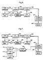
- signals identifying the XY location of the spots on CCD arrays 28 and 38 are delivered to CCD evaluating electronics 56 by leads 58 and 60.
- Electronics 56 compares the reported XY position of the spot to the stored reference location for each CCD array.
- An output from electronics 56 representing the location of the spot relative to the reference location is provided to display electronics 62 which in turn drives CRT 66 through leads 64 to provide symbols on CRT 66.
- the signal from video image detector 44 is similarly provided to display electronics 62 through lead 68 in order to provide a macro image of the eye on CRT 66.
- the location of the spot on a CCD array can be identified conveniently using a raster sweep of the CCD pixel signals.
- the signal and location values of the first pixel are stored until a higher signal value is encountered during the sweep. Each time a higher signal value is encountered, the new pixel signal and location values are stored replacing the values previously stored until the sweep is complete.
- the location values stored at the end of the sweep identify the center of the spot on the respective CCD array. If a minimum signal threshold is set, artifacts, such as glare spots that can result from illumination for the macro view, are ignored by the system.
- the timing of the raster sweep of CCD array 228 is synchronized with the strobe of sources 14 and 16 in order that even raster sweeps relate to one source and odd raster sweeps to the other.
- a preferred optical system according to Fig. 2 is diagrammatically presented in Fig. 5 and has the following values: wherein, radii, R1 to R6, thicknesses, T1 to T5, spacings, S1 to S11, pinhole diameters, D1 and D2, are in mm; radii having their center of curvature on the eye 10 side of the lens are indicated by a minus (-) sign; and indexes of refraction, N1 to N3, are absolute values.
- the pinhole-lens combinations can be replaced by small diameter lenses if desired.
- the model Texas Instruments TC211 CCD array is suitable for practicing this invention.
- the amount of movement can be presented two dimensionally, for example on the CRT, by using one symbol for the horizonal (x) axis and another for the vertical (y) axis.
- the space between the symbols can be used to represent ⁇ S9.
- a simpler and more user-friendly procedure is the use of a cursor which moves above the screen center, if the instrument is too far from the object and below the screen center, if the instrument is too close.
- the cursor type of presentation is preferred because it has several advantages.
- One advantage is the ease with which the user can recognize whether the instrument is too close or too far away.
- Another advantage is that the x and y positions can be displayed by means that do not require superimposition of symbols to indicate correct positioning. For example, a narrow vertical line can be used to represent the relative horizonal position and a narrow horizonal line to indicate the relative vertical position, while the cursor indicates the relative distance from the object.
- Prior art alignment systems did not permit
- signals from timing generator 350 drive x/y counters 352, the raster sweep of CCD array 354 and timing of A/D converter 358.
- Each pixel signal is amplified by amplifier 356, sent to A/D converter 358, whose output is evaluated by peak detector 360.
- the outputs of x/y counters 352 are stored by latches 362, each time peak detector 360 signals a new high for the pixel signals from CCD array 354.
- each array requires an amplifier, A/D converter, peak detector and output latches.
- the outputs of latches 362 are evaluated at the end of each raster sweep by alignment and calibration electronics 364 which updates operator display 366.
- motor controllers 368 and motors 370, 372 and 374 can be added as shown in Fig. 7.
Landscapes
- Life Sciences & Earth Sciences (AREA)
- Health & Medical Sciences (AREA)
- Medical Informatics (AREA)
- Biophysics (AREA)
- Ophthalmology & Optometry (AREA)
- Engineering & Computer Science (AREA)
- Biomedical Technology (AREA)
- Heart & Thoracic Surgery (AREA)
- Physics & Mathematics (AREA)
- Molecular Biology (AREA)
- Surgery (AREA)
- Animal Behavior & Ethology (AREA)
- General Health & Medical Sciences (AREA)
- Public Health (AREA)
- Veterinary Medicine (AREA)
- Eye Examination Apparatus (AREA)
- Prostheses (AREA)
Claims (14)
- Ein Ausrichtsystem für ein Opthalmieinstrument (1), mit Beleuchtungseinrichtungen (14,16) für die Beleuchtung eines Auges (10) und einer Erfassungseinrichtung (28,38) für die Erfassung von von einem Auge (10) reflektierten Strahlen, dadurch gekennzeichnet, daß die Beleuchtungseinrichtungen (14,16) so angeordnet sind, daß sie das Auge (10) mit divergierenden Strahlen von einer Lichtquelle beleuchten, und daß die Erfassungseinrichtung eine erste Erfassungseinrichtung (28) und eine zweite Erfassungseinrichtung (38) umfaßt, wobei die erste Erfassungseinrichtung (28) einen ersten Lichterfassungsbereich besitzt und einen ersten Lochblendenschirm (24) aufweist, durch den ein kleines Bündel von vom Auge (10) reflektierten Strahlen verläuft, um ein erstes Signal zu erzeugen, das die XY-Position des reflektierten Lichts auf dem ersten Bereich identifiziert; wobei die zweite Erfassungseinrichtung (38) einen zweiten Lichterfassungsbereich besitzt und einen zweiten Lochblendenschirm (34) aufweist, durch den ein kleines Bündel von vom Auge (10) reflektierten Strahlen verläuft, um ein zweites Signal zu erzeugen, das die XY-Position des reflektierten Lichts auf dem zweiten Bereich identifiziert; wobei das System ferner gekennzeichnet ist durch eine Einrichtung (56) für die Auswertung der ersten und der zweiten Signale, um ein drittes Signal zu erzeugen; und durch automatische oder manuelle Positioniereinrichtungen (6;368,317,372,374), mit denen das Instrument entsprechend dem dritten Signal relativ zum Auge positioniert werden kann.
- Ein System gemäß Anspruch 1, dadurch gekennzeichnet, daß die Positioniereinrichtung (368,370,372,374) manuell betätigte Einrichtungen (6,9) für die Bewegung des Instruments (1) sowie eine Anzeigeeinrichtung (8) enthält, um eine visuelle Angabe der Instrumentenposition zu erzeugen.
- Ein System gemäß einem der vorangehenden Ansprüche, dadurch gekennzeichnet, daß die Beleuchtungseinrichtung (14,16) zwei Lichtwege (18,30) aufweist, wobei einer der beiden Wege (18) Licht von einer Seite auf ein Auge (10) richtet und der andere der beiden Wege (30) Licht von der anderen Seite auf das Auge (10) richtet.
- Ein System gemäß Anspruch 3, dadurch gekennzeichnet, daß die Beleuchtungseinrichtung (14,16) und die Erfassungseinrichtung (28,38) so angeordnet sind, daß die erste Erfassungseinrichtung (28) mit reflektiertem Licht vom ersten Lichtweg (30) bestrahlt wird und die zweite Erfassungseinrichtung (38) mit reflektiertem Licht vom zweiten Lichtweg (18) bestrahlt wird.
- Ein System gemäß einem der vorangehenden Ansprüche, dadurch gekennzeichnet, daß jede der ersten und zweiten Erfassungseinrichtungen (28,38) in der Nähe des Lochblendenschirms (24) eine Sammellinse (26,36) enthält.
- Ein System gemäß einem der vorangehenden Ansprüche, gekennzeichnet durch eine elektrooptische Einrichtung (44) für die Erzeugung eines vierten Signals, das ein Makrobild des Auges (10) darstellt.
- Ein System gemäß einem der vorangehenden Ansprüche, dadurch gekennzeichnet, daß die Auswertungseinrichtung (56) eine Speichereinrichtung (362) aufweist, die Information hält, die die erste und die zweite Referenzposition auf dem ersten bzw. dem zweiten Bereich darstellt, wobei die Referenzpositionen eine erste und eine zweite Position symbolisieren, die von reflektiertem Licht bestrahlt werden, wenn das Instrument an einer gewählten Position relativ zu einem Auge (10) positioniert ist, und das dritte Signal einen Vergleich des ersten und des zweiten Signals mit der Information enthält.
- Ein System gemäß einem der vorangehenden Ansprüche, dadurch gekennzeichnet, daß die Positioniereinrichtung eine elektromechanische Einrichtung (370,372,374) für die Bewegung des Instrumentes (1) enthält.
- Ein Ausrichtsystem für ein Opthalmieinstrument (1), mit einer Beleuchtungseinrichtung (14,16) für die Beleuchtung eines Auges (10) und einer Erfassungseinrichtung (228) für die Erfassung von vom Auge (10) reflektierten Strahlen, dadurch gekennzeichnet, daß die Beleuchtungseinrichtung (14,16) eine erste Beleuchtungseinrichtung (14), die das Auge (10) mit divergierenden Strahlen von einer seiner Seiten beleuchtet, sowie eine zweite Beleuchtungseinrichtung (16) aufweist, die das Auge (10) mit divergierenden Strahlen von der anderen Seite desselben beleuchtet; und daß die Erfassungseinrichtung eine Lichterfassungseinrichtung (228) mit einem Lichterfassungsbereich umfaßt und einen Schirm (224) mit zwei beabstandeten Lochblenden (252,254) aufweist, durch die zwei kleine Bündel von vom Auge (10) reflektierten Strahlen verlaufen, wobei eines der Bündel Strahlen von der ersten Beleuchtungseinrichtung (14) und das andere der Bündel Strahlen von der zweiten der Beleuchtungseinrichtungen (16) enthält, um ein erstes bzw. ein zweites Signal zu erzeugen, die die XY-Position des durch jedes der Lochblenden (252,254) verlaufenden reflektierten Lichts zu identifizieren; wobei das System ferner gekennzeichnet ist durch eine Einrichtung (364) für die Auswertung der Signale, um ein Ausgangssignal zu erzeugen; und durch Einrichtungen (368,370,372,374) für die Positionierung des Instruments (1) relativ zum Auge (10) anhand des Ausgangssignals.
- Ein System gemäß Anspruch 9, dadurch gekennzeichnet, daß die Erfassungseinrichtung (228) in der Nähe des Schirms (224) eine Sammellinse (226) enthält.
- Ein System gemäß Anspruch 9 oder 10, gekennzeichnet durch eine elektrooptische Einrichtung (44), die ein Videosignal erzeugt, das ein Makrobild des Auges (10) darstellt.
- Ein System gemäß einem der Ansprüche 9, 10 und 11, dadurch gekennzeichnet, daß die Positioniereinrichtung (368,370,372,374) eine manuell betätigte Einrichtung (6) für die Bewegung des Instruments sowie eine Anzeigeinrichtung (8) enthält, um eine visuelle Angabe der Instrumentenposition zu erzeugen.
- Ein System gemäß Anspruch 12, gekennzeichnet durch eine Strahlteilereinrichtung (250), um unter Verwendung eines Anteils des Lichts von wenigstens einer der ersten und zweiten Beleuchtungseinrichtungen (14,16) ein Makrobild des Auges (10) zu erzeugen.
- Ein System gemäß einem der Ansprüche 9 bis 13, dadurch gekennzeichnet, daß die Positioniereinrichtung elektromechanische Einrichtungen (370,372,374) für die Bewegung des Instruments (1) enthält.
Priority Applications (1)
| Application Number | Priority Date | Filing Date | Title |
|---|---|---|---|
| AT89307824T ATE100295T1 (de) | 1988-08-05 | 1989-08-01 | Vorrichtung zum ausrichten eines ophthalmologischen instruments. |
Applications Claiming Priority (2)
| Application Number | Priority Date | Filing Date | Title |
|---|---|---|---|
| US228482 | 1988-08-05 | ||
| US07/228,482 US4881807A (en) | 1988-08-05 | 1988-08-05 | Optical alignment system |
Publications (2)
| Publication Number | Publication Date |
|---|---|
| EP0354002A1 EP0354002A1 (de) | 1990-02-07 |
| EP0354002B1 true EP0354002B1 (de) | 1994-01-19 |
Family
ID=22857354
Family Applications (1)
| Application Number | Title | Priority Date | Filing Date |
|---|---|---|---|
| EP89307824A Expired - Lifetime EP0354002B1 (de) | 1988-08-05 | 1989-08-01 | Vorrichtung zum Ausrichten eines ophthalmologischen Instruments |
Country Status (7)
| Country | Link |
|---|---|
| US (1) | US4881807A (de) |
| EP (1) | EP0354002B1 (de) |
| JP (1) | JP2649088B2 (de) |
| AT (1) | ATE100295T1 (de) |
| CA (1) | CA1311608C (de) |
| DE (1) | DE68912444T2 (de) |
| ES (1) | ES2049325T3 (de) |
Cited By (1)
| Publication number | Priority date | Publication date | Assignee | Title |
|---|---|---|---|---|
| EP1125544A2 (de) * | 2000-02-10 | 2001-08-22 | Carl Zeiss | Verfahren und Vorrichtung zur Bestimmung der Augenposition |
Families Citing this family (25)
| Publication number | Priority date | Publication date | Assignee | Title |
|---|---|---|---|---|
| US5585873A (en) * | 1991-10-11 | 1996-12-17 | Alcon Laboratories, Inc. | Automated hand-held keratometer |
| US5436679A (en) * | 1991-11-29 | 1995-07-25 | Kabushiki Kaisha Topcon | Apparatus for observing and photographing a corneal endothelium |
| US5270748A (en) * | 1992-01-30 | 1993-12-14 | Mak Technologies, Inc. | High-speed eye tracking device and method |
| US5526072A (en) * | 1993-04-14 | 1996-06-11 | Alcon Laboratories, Inc. | Apparatus and technique for automatic centering and focusing a corneal topographer |
| JPH07231875A (ja) * | 1994-02-24 | 1995-09-05 | Canon Inc | 検眼装置 |
| US5532769A (en) * | 1994-03-31 | 1996-07-02 | Nidek Co., Ltd. | Ophthalmologic alignment device with automatic alignment means |
| USRE43097E1 (en) | 1994-10-13 | 2012-01-10 | Illumina, Inc. | Massively parallel signature sequencing by ligation of encoded adaptors |
| US5587748A (en) * | 1994-10-28 | 1996-12-24 | Leica Inc. | Joystick override control for an ophthalmic instrument |
| DE19512711C1 (de) * | 1995-04-10 | 1996-12-12 | Visionet Ges Fuer Mikrotechnis | Verfahren zur Messung des Augeninnendruckes |
| US5754273A (en) * | 1997-02-21 | 1998-05-19 | Leica Inc. | Non-contact tonometer having off-axis fluid pulse system |
| US6048065A (en) * | 1998-09-16 | 2000-04-11 | Vismed, Incorporated | Distance optimizing apparatus for a placido-based eye observation system |
| US6361495B1 (en) | 2000-02-07 | 2002-03-26 | Leica Microsystems Inc. | Hand-held non-contact tonometer |
| US6667761B1 (en) | 2000-04-14 | 2003-12-23 | Imaging & Sensing Technology Corporation | Instrument visualization system |
| US6749302B2 (en) | 2001-11-06 | 2004-06-15 | Reichert, Inc. | Afocal position detection system and ophthalmic instrument employing said system |
| US6669340B2 (en) | 2001-11-06 | 2003-12-30 | Reichert, Inc. | Alignment system for an ophthalmic instrument |
| US6945650B2 (en) | 2001-11-06 | 2005-09-20 | Reichert, Inc. | Alignment system for hand-held ophthalmic device |
| US20030092979A1 (en) | 2001-11-09 | 2003-05-15 | Leica Microsystems Inc. | Non-contact tonometer having fluid pump driven by proportional solenoid |
| US6817981B2 (en) | 2002-07-01 | 2004-11-16 | Reichert, Inc. | Method for eliminating error in tonometric measurements |
| US7338167B2 (en) * | 2003-12-10 | 2008-03-04 | Joslin Diabetes Center, Inc. | Retinal imaging system |
| RU2268637C2 (ru) * | 2004-03-22 | 2006-01-27 | Андрей Викторович Ларичев | Аберрометр с системой тестирования остроты зрения (варианты), устройство и способ его настройки |
| US7478908B2 (en) * | 2006-09-27 | 2009-01-20 | Bausch & Lomb Incorporated | Apparatus and method for determining a position of an eye |
| US20090096987A1 (en) * | 2007-10-10 | 2009-04-16 | Ming Lai | Eye Measurement Apparatus and a Method of Using Same |
| ES2701608T3 (es) * | 2011-03-25 | 2019-02-25 | Novartis Ag | Aparato y procedimiento para modelar estructuras oculares |
| JP6437249B2 (ja) * | 2014-08-29 | 2018-12-12 | 株式会社トプコン | 眼科装置 |
| US11219367B2 (en) | 2020-01-30 | 2022-01-11 | Reichert, Inc. | Positioning system for ophthalmic instrument |
Citations (2)
| Publication number | Priority date | Publication date | Assignee | Title |
|---|---|---|---|---|
| DE3138122A1 (de) * | 1980-09-24 | 1982-04-22 | Tokyo Kogaku Kikai K.K., Tokyo | Augenuntersuchungsinstrument mit einer einrichtung zum automatischen anzeigen der richtigen stellung des zu untersuchenden auges |
| US4678297A (en) * | 1982-11-30 | 1987-07-07 | Canon Kabushiki Kaisha | Ophthalmic instrument |
Family Cites Families (7)
| Publication number | Priority date | Publication date | Assignee | Title |
|---|---|---|---|---|
| JPS5897340A (ja) * | 1981-12-07 | 1983-06-09 | キヤノン株式会社 | 眼科機器の位置合わせ装置 |
| JPS60145119A (ja) * | 1983-12-30 | 1985-07-31 | キヤノン株式会社 | 眼屈折力測定装置 |
| US4662730A (en) * | 1984-10-18 | 1987-05-05 | Kerascan, Inc. | Scanning keratometers |
| EP0183621B1 (de) * | 1984-11-27 | 1992-09-02 | Kabushiki Kaisha TOPCON | Berührungsloses Tonometer |
| JPH0753151B2 (ja) * | 1986-07-17 | 1995-06-07 | 株式会社トプコン | 眼科測定装置 |
| JP2588881B2 (ja) * | 1986-09-06 | 1997-03-12 | 株式会社 トプコン | 非接触式眼圧計 |
| JPS6397141A (ja) * | 1986-10-14 | 1988-04-27 | キヤノン株式会社 | 眼圧計 |
-
1988
- 1988-08-05 US US07/228,482 patent/US4881807A/en not_active Expired - Lifetime
-
1989
- 1989-07-21 CA CA000606484A patent/CA1311608C/en not_active Expired - Lifetime
- 1989-08-01 AT AT89307824T patent/ATE100295T1/de not_active IP Right Cessation
- 1989-08-01 EP EP89307824A patent/EP0354002B1/de not_active Expired - Lifetime
- 1989-08-01 DE DE89307824T patent/DE68912444T2/de not_active Expired - Fee Related
- 1989-08-01 ES ES89307824T patent/ES2049325T3/es not_active Expired - Lifetime
- 1989-08-05 JP JP1202300A patent/JP2649088B2/ja not_active Expired - Fee Related
Patent Citations (2)
| Publication number | Priority date | Publication date | Assignee | Title |
|---|---|---|---|---|
| DE3138122A1 (de) * | 1980-09-24 | 1982-04-22 | Tokyo Kogaku Kikai K.K., Tokyo | Augenuntersuchungsinstrument mit einer einrichtung zum automatischen anzeigen der richtigen stellung des zu untersuchenden auges |
| US4678297A (en) * | 1982-11-30 | 1987-07-07 | Canon Kabushiki Kaisha | Ophthalmic instrument |
Cited By (1)
| Publication number | Priority date | Publication date | Assignee | Title |
|---|---|---|---|---|
| EP1125544A2 (de) * | 2000-02-10 | 2001-08-22 | Carl Zeiss | Verfahren und Vorrichtung zur Bestimmung der Augenposition |
Also Published As
| Publication number | Publication date |
|---|---|
| DE68912444D1 (de) | 1994-03-03 |
| DE68912444T2 (de) | 1994-05-11 |
| ATE100295T1 (de) | 1994-02-15 |
| JPH0282939A (ja) | 1990-03-23 |
| US4881807A (en) | 1989-11-21 |
| EP0354002A1 (de) | 1990-02-07 |
| ES2049325T3 (es) | 1994-04-16 |
| CA1311608C (en) | 1992-12-22 |
| JP2649088B2 (ja) | 1997-09-03 |
Similar Documents
| Publication | Publication Date | Title |
|---|---|---|
| EP0354002B1 (de) | Vorrichtung zum Ausrichten eines ophthalmologischen Instruments | |
| US5751396A (en) | Ophthalmic apparatus including ocular fundus illuminating system for illuminating the fundus of the eye to be examined through the pupil thereof | |
| US6580448B1 (en) | Process and device for the parallel capture of visual information | |
| US5225862A (en) | Visual axis detector using plural reflected image of a light source | |
| US4944303A (en) | Noncontact type tonometer | |
| US5557350A (en) | Ophthalmometric apparatus with alignment device including filter means | |
| US5757461A (en) | Method for displaying a photographing point of a cornea in an apparatus for obtaining video images of corneal cells | |
| EP1452128B1 (de) | Funduskamera | |
| US5625428A (en) | Ophthalmic apparatus with alignment indicating system | |
| US7354153B2 (en) | Fundus camera | |
| US4960327A (en) | Optical system in a lasar scanning eye fundus camera | |
| US5504543A (en) | Ophthalmic photographing apparatus having control means for stopping the operation and fixing the in-focus state | |
| US6409344B1 (en) | Ocular refractive-power measuring device | |
| US5337095A (en) | Ophthalmological instrument | |
| US6304723B1 (en) | Retinal camera | |
| JPH08565A (ja) | 眼科装置 | |
| JP2812421B2 (ja) | 角膜細胞撮影装置 | |
| US5571108A (en) | Binocular stereo microscope | |
| EP1021983B1 (de) | Kompakte Gesichtsfeldtestanordnung | |
| JPH06160727A (ja) | 眼球顕微鏡 | |
| JP2831546B2 (ja) | 角膜撮影位置表示方法およびその装置 | |
| JPH08289874A (ja) | 眼底カメラ | |
| JPH07241272A (ja) | 角膜形状測定装置 | |
| JPH0994229A (ja) | 角膜内皮細胞観察撮影装置 | |
| JPH0315438A (ja) | 眼科機器のアライメント装置 |
Legal Events
| Date | Code | Title | Description |
|---|---|---|---|
| PUAI | Public reference made under article 153(3) epc to a published international application that has entered the european phase |
Free format text: ORIGINAL CODE: 0009012 |
|
| AK | Designated contracting states |
Kind code of ref document: A1 Designated state(s): AT BE DE ES FR GB GR IT LU NL |
|
| 17P | Request for examination filed |
Effective date: 19900702 |
|
| 17Q | First examination report despatched |
Effective date: 19920610 |
|
| RAP1 | Party data changed (applicant data changed or rights of an application transferred) |
Owner name: LEICA INC. |
|
| GRAA | (expected) grant |
Free format text: ORIGINAL CODE: 0009210 |
|
| AK | Designated contracting states |
Kind code of ref document: B1 Designated state(s): AT BE DE ES FR GB GR IT LU NL |
|
| REF | Corresponds to: |
Ref document number: 100295 Country of ref document: AT Date of ref document: 19940215 Kind code of ref document: T |
|
| ITF | It: translation for a ep patent filed | ||
| REF | Corresponds to: |
Ref document number: 68912444 Country of ref document: DE Date of ref document: 19940303 |
|
| REG | Reference to a national code |
Ref country code: ES Ref legal event code: FG2A Ref document number: 2049325 Country of ref document: ES Kind code of ref document: T3 |
|
| REG | Reference to a national code |
Ref country code: GR Ref legal event code: FG4A Free format text: 3010819 |
|
| ET | Fr: translation filed | ||
| EPTA | Lu: last paid annual fee | ||
| PLBE | No opposition filed within time limit |
Free format text: ORIGINAL CODE: 0009261 |
|
| STAA | Information on the status of an ep patent application or granted ep patent |
Free format text: STATUS: NO OPPOSITION FILED WITHIN TIME LIMIT |
|
| 26N | No opposition filed | ||
| REG | Reference to a national code |
Ref country code: GB Ref legal event code: IF02 |
|
| PGFP | Annual fee paid to national office [announced via postgrant information from national office to epo] |
Ref country code: NL Payment date: 20020725 Year of fee payment: 14 Ref country code: LU Payment date: 20020725 Year of fee payment: 14 Ref country code: BE Payment date: 20020725 Year of fee payment: 14 |
|
| PGFP | Annual fee paid to national office [announced via postgrant information from national office to epo] |
Ref country code: AT Payment date: 20020729 Year of fee payment: 14 |
|
| PGFP | Annual fee paid to national office [announced via postgrant information from national office to epo] |
Ref country code: GR Payment date: 20020822 Year of fee payment: 14 |
|
| PGFP | Annual fee paid to national office [announced via postgrant information from national office to epo] |
Ref country code: GB Payment date: 20030728 Year of fee payment: 15 |
|
| PG25 | Lapsed in a contracting state [announced via postgrant information from national office to epo] |
Ref country code: LU Free format text: LAPSE BECAUSE OF NON-PAYMENT OF DUE FEES Effective date: 20030801 Ref country code: AT Free format text: LAPSE BECAUSE OF NON-PAYMENT OF DUE FEES Effective date: 20030801 |
|
| PGFP | Annual fee paid to national office [announced via postgrant information from national office to epo] |
Ref country code: DE Payment date: 20030805 Year of fee payment: 15 |
|
| PGFP | Annual fee paid to national office [announced via postgrant information from national office to epo] |
Ref country code: ES Payment date: 20030807 Year of fee payment: 15 |
|
| PGFP | Annual fee paid to national office [announced via postgrant information from national office to epo] |
Ref country code: FR Payment date: 20030813 Year of fee payment: 15 |
|
| PG25 | Lapsed in a contracting state [announced via postgrant information from national office to epo] |
Ref country code: BE Free format text: LAPSE BECAUSE OF NON-PAYMENT OF DUE FEES Effective date: 20030831 |
|
| BERE | Be: lapsed |
Owner name: *LEICA INC. Effective date: 20030831 |
|
| PG25 | Lapsed in a contracting state [announced via postgrant information from national office to epo] |
Ref country code: NL Free format text: LAPSE BECAUSE OF NON-PAYMENT OF DUE FEES Effective date: 20040301 |
|
| PG25 | Lapsed in a contracting state [announced via postgrant information from national office to epo] |
Ref country code: GR Free format text: LAPSE BECAUSE OF NON-PAYMENT OF DUE FEES Effective date: 20040303 |
|
| NLV4 | Nl: lapsed or anulled due to non-payment of the annual fee |
Effective date: 20040301 |
|
| PG25 | Lapsed in a contracting state [announced via postgrant information from national office to epo] |
Ref country code: GB Free format text: LAPSE BECAUSE OF NON-PAYMENT OF DUE FEES Effective date: 20040801 |
|
| PG25 | Lapsed in a contracting state [announced via postgrant information from national office to epo] |
Ref country code: ES Free format text: LAPSE BECAUSE OF NON-PAYMENT OF DUE FEES Effective date: 20040802 |
|
| PG25 | Lapsed in a contracting state [announced via postgrant information from national office to epo] |
Ref country code: DE Free format text: LAPSE BECAUSE OF NON-PAYMENT OF DUE FEES Effective date: 20050301 |
|
| GBPC | Gb: european patent ceased through non-payment of renewal fee |
Effective date: 20040801 |
|
| PG25 | Lapsed in a contracting state [announced via postgrant information from national office to epo] |
Ref country code: FR Free format text: LAPSE BECAUSE OF NON-PAYMENT OF DUE FEES Effective date: 20050429 |
|
| REG | Reference to a national code |
Ref country code: FR Ref legal event code: ST |
|
| PG25 | Lapsed in a contracting state [announced via postgrant information from national office to epo] |
Ref country code: IT Free format text: LAPSE BECAUSE OF NON-PAYMENT OF DUE FEES;WARNING: LAPSES OF ITALIAN PATENTS WITH EFFECTIVE DATE BEFORE 2007 MAY HAVE OCCURRED AT ANY TIME BEFORE 2007. THE CORRECT EFFECTIVE DATE MAY BE DIFFERENT FROM THE ONE RECORDED. Effective date: 20050801 |
|
| REG | Reference to a national code |
Ref country code: ES Ref legal event code: FD2A Effective date: 20040802 |