EP0353863B1 - Steuerverfahren für die Ventilsteuerzeitumschaltung in einer Brennkraftmaschine - Google Patents
Steuerverfahren für die Ventilsteuerzeitumschaltung in einer Brennkraftmaschine Download PDFInfo
- Publication number
- EP0353863B1 EP0353863B1 EP89306638A EP89306638A EP0353863B1 EP 0353863 B1 EP0353863 B1 EP 0353863B1 EP 89306638 A EP89306638 A EP 89306638A EP 89306638 A EP89306638 A EP 89306638A EP 0353863 B1 EP0353863 B1 EP 0353863B1
- Authority
- EP
- European Patent Office
- Prior art keywords
- valve timing
- speed
- engine
- fuel injection
- valve
- Prior art date
- Legal status (The legal status is an assumption and is not a legal conclusion. Google has not performed a legal analysis and makes no representation as to the accuracy of the status listed.)
- Expired - Lifetime
Links
Images


Classifications
-
- F—MECHANICAL ENGINEERING; LIGHTING; HEATING; WEAPONS; BLASTING
- F02—COMBUSTION ENGINES; HOT-GAS OR COMBUSTION-PRODUCT ENGINE PLANTS
- F02D—CONTROLLING COMBUSTION ENGINES
- F02D13/00—Controlling the engine output power by varying inlet or exhaust valve operating characteristics, e.g. timing
- F02D13/02—Controlling the engine output power by varying inlet or exhaust valve operating characteristics, e.g. timing during engine operation
- F02D13/0203—Variable control of intake and exhaust valves
- F02D13/0207—Variable control of intake and exhaust valves changing valve lift or valve lift and timing
-
- F—MECHANICAL ENGINEERING; LIGHTING; HEATING; WEAPONS; BLASTING
- F01—MACHINES OR ENGINES IN GENERAL; ENGINE PLANTS IN GENERAL; STEAM ENGINES
- F01L—CYCLICALLY OPERATING VALVES FOR MACHINES OR ENGINES
- F01L1/00—Valve-gear or valve arrangements, e.g. lift-valve gear
- F01L1/26—Valve-gear or valve arrangements, e.g. lift-valve gear characterised by the provision of two or more valves operated simultaneously by same transmitting-gear; peculiar to machines or engines with more than two lift-valves per cylinder
- F01L1/267—Valve-gear or valve arrangements, e.g. lift-valve gear characterised by the provision of two or more valves operated simultaneously by same transmitting-gear; peculiar to machines or engines with more than two lift-valves per cylinder with means for varying the timing or the lift of the valves
-
- F—MECHANICAL ENGINEERING; LIGHTING; HEATING; WEAPONS; BLASTING
- F02—COMBUSTION ENGINES; HOT-GAS OR COMBUSTION-PRODUCT ENGINE PLANTS
- F02B—INTERNAL-COMBUSTION PISTON ENGINES; COMBUSTION ENGINES IN GENERAL
- F02B2275/00—Other engines, components or details, not provided for in other groups of this subclass
- F02B2275/18—DOHC [Double overhead camshaft]
-
- Y—GENERAL TAGGING OF NEW TECHNOLOGICAL DEVELOPMENTS; GENERAL TAGGING OF CROSS-SECTIONAL TECHNOLOGIES SPANNING OVER SEVERAL SECTIONS OF THE IPC; TECHNICAL SUBJECTS COVERED BY FORMER USPC CROSS-REFERENCE ART COLLECTIONS [XRACs] AND DIGESTS
- Y02—TECHNOLOGIES OR APPLICATIONS FOR MITIGATION OR ADAPTATION AGAINST CLIMATE CHANGE
- Y02T—CLIMATE CHANGE MITIGATION TECHNOLOGIES RELATED TO TRANSPORTATION
- Y02T10/00—Road transport of goods or passengers
- Y02T10/10—Internal combustion engine [ICE] based vehicles
- Y02T10/12—Improving ICE efficiencies
Definitions
- This invention relates to a valve-timing changeover control method applied to an electronically controlled fuel injection type engine.
- an electronic control circuit comprising a micro-computer is used to calculate a fuel injection quantity by taking into account various parameters representing the operating condition of the engine. More specifically, when it is determined that a high load is being applied to the engine in view of such parameters as engine revolution speed, intake negative pressure, throttle opening, engine's water temperature, intake temperature, atmospheric pressure, etc., the fuel injection quantity is increased to enrich the air-fuel mixture. Under such a high-load operation of the engine, it is of advantage to the engine operation that the valve timing is changed over to the high-speed one.
- valve timing is changed over only on the basis of the revolution speed of the engine and the intake negative pressure as in case of the prior art, it is simply not possible to change over the valve timing to the high-speed one to conform to a required fuel injection increase that is determined from a number of parameters as described above.
- valve timing changeover refers to changing one or both of the valve-open duration and valve-lift amount.
- the valve timing changeover referred to herein also covers that, in a multi-valve engine, any one of a plurality of intake or exhaust valves for each cylinder of the engine is put to a quiescent position according to the operating condition of the engine.
- a standard fuel injection quantity is predetermined for each of the low-speed valve timing and the high-speed valve timing and selected in accordance with changeover from one valve timing to the other so that the fuel injection quantity may be calculated on the basis of said standard fuel injection quantity selected according to the valve timing selected. Therefore, when the valve timing is changed over to the high-speed one in the high-load region as described above, the fuel injection is supposed to be carried out so as to ensure the fuel injection quantity calculated on basis of said standard fuel injection quantity predetermined for the high-speed valve timing.
- valve-timing changeover means or the like there are cases in which, due to a malfunction or the like of the valve-timing changeover means or the like, the valve timing is not changed over as instructed or is belatedly changed over because of a response delay. If the standard fuel injection quantity predetermined for the high-speed valve timing is selected as soon as the operating condition has entered the high-load region in such cases, there can occur a situation where fuel injection providing the injection quantity suitable for the engine operation with the high-speed valve timing is performed when the intake and exhaust valves are actually operating to open and close with the low-speed valve timing. This causes the mixture to become excessively enriched, adversely affecting the emission performance and the catalyzer.
- a confirmation means is provided to confirm that the valve timing has been changed over properly, so that when the proper valve-timing changeover is not confirmed by this confirmation means, the fuel injection with the fuel injection quantity selected to conform to the valve timing before the changeover may be continued.
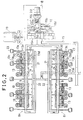
- reference numeral 1 denotes an engine body
- 2 denotes an intake passage
- 3 designates an exhaust passage.
- the intake passage 2 is provided with an air cleaner 4, a throttle valve 5 and an injector 6 in that order from the upstream side and quantity of fuel injection made through said injector 6 is variably controlled by an electronic control circuit 7, so that the engine arranged as above is an electronically controlled fuel injection type.
- the engine used in this embodiment example of the present invention is a double overhead cam (DOHC), in-line four-cylinder engine having a pair of intake and exhaust valves for each cylinder and, as shown in Figure 2, it is further provided with a valve mechanism 8e at the exhaust valve side, said valve mechanisms being operated to drive these intake and exhaust valves to open and close.
- DOHC double overhead cam
- in-line four-cylinder engine having a pair of intake and exhaust valves for each cylinder and, as shown in Figure 2, it is further provided with a valve mechanism 8e at the exhaust valve side, said valve mechanisms being operated to drive these intake and exhaust valves to open and close.
- valve mechanisms 8i and 8e are basically of the same construction, so that detailed explanation will be made only of the intake-side valve mechanism hereinbelow while omitting that of the exhaust-side valve mechanism. Note that both of said valve mechanisms are assigned with same symbols and reference numerals for their corresponding parts.
- the intake-side valve mechanism 8i comprises: a rocker shaft 9 for the intake valves; a pair of driving rocker arms 10, 11 pivotally supported on the rocker shaft 9 for driving a pair of the intake valves of each cylinder and a free rocker arm 12 located intermediately between said pair of the driving rocker arms 10, 11 and also pivotally supported on said rocker shaft 9, said driving rocker arms 10, 11 being interlocked with a low-speed cam formed on a cam shaft for the intake valves and said free rocker arm 12 being interlocked with a high-speed cam formed on the cam shaft; and a changeover mechanism 13 through which both the driving rocker arms 10, 11 are detachably connected to the free rocker arm 12.
- the intake valves are operated to open and close with a low-speed valve timing at which the valve-open duration and the valve-lift amount are made relatively smaller by means of the low-speed cam.
- the intake valves are operated at a high-speed valve timing at which the valve-open duration and the valve-lift amount are relatively larger.
- the changeover mechanism 13 comprises: a first connecting pin 13a which can be engaged with and disengaged from the free rocker arm 12, said first connecting pin 13a being inserted in the first driving rocker arm 10, that is, one of the two driving rocker arms 10, 11; a second connecting pin 13b which can be engaged with and disengaged from the second driving rocker arm 11, that is, the other of the two driving rocker arms 10, 11, said second connecting pin 13b being inserted in the free rocker arm 12; and a restriction pin 13d urged towards the free rocker arm 12 by a spring 13c inserted in the second driving rocker arm 11.
- a hydraulic chamber 13e providing an oil pressure to push the first connecting pin 13a towards the free rocker arm 12, said hydraulic chamber 13e being communicated with an oil supplying passage 14 formed in the rocker shaft 9.
- the hydraulic chamber 13e is charged with a hydraulic oil through the oil-supplying passage 14, the first connecting pin 13a becomes engaged with the free rocker arm 12 and, pushed by the first connecting pin 13a, the second connecting pin 13b comes to engage with the second driving rocker arm 11, so that both the driving rocker arms 10, 11 and the free rocker arm 12 are connected to each other to change the valve timing to a high-speed one.
- an oil passage 15 for supplying oil from an oil pump not shown is connected to the aforementioned oil supplying passage 14 through a changeover valve 16 attached to an end portion of the cylinder head, so that when a spool type valve body 16a of the changeover valve 16 is positioned at the upper closed position, an inlet port 16b communicating with the oil passage 15 through an oil filter 17 and an outlet port 16c communicating with the oil supplying passage 14 may be communicated with each other only through an orifice 16d. At this time, the outlet port 16c comes to be communicated with a drain port 16e which opens in the upper space in the cylinder head with the result that the oil pressure in the oil supplying passage 14 is decreased.
- the spool type valve body 16a is arranged such that the changeover thereof to the open position is carried out against the urging force of a spring 16f by pilot pressure inputted through a pilot oil passage 18 branching out from the inlet port 16b.
- the pilot oil passage 18 is provided with a normally closed type electromagnetic valve 19.
- An electric current to energize a solenoid 19a of the electromagnetic valve 19 is controlled by output signal VTS from the electronic control circuit 7 as shown in Figure 1.
- the electromagnetic valve 19 is opened with energization of the solenoid 19a (shown in Figure 1), the spool type valve body 16a is moved to its open position so that the valve timing is changed over to a high-speed one as described in the foregoing.
- the electric current energizing the solenoid 19a is stopped to close the electromagnetic valve 19, the spool type valve body 16a is changed over to the closed position so that the valve timing is changed over to a low-speed one.
- a hydraulic switch 20 that detects oil pressure at the outlet port 16c and turns on when the detected oil pressure is low and turns off when the detected oil pressure is high.
- reference numeral 21 denotes a lubricant passage of the valve mechanism
- 22 designates a lubricant passage of the valve mechanism for the high-speed valve timing operation
- 23 denotes a cam holder.
- Inputted in the electronic control circuit 7 are engine revolution speed (Ne) signals from an engine revolution speed sensor, throttle opening-degree ( ⁇ th) signals from a throttle opening sensor 24, intake negative pressure (P B ) signals and intake temperature (TA) signals, respectively, from a pressure sensor 25 and a temperature sensor 26, both of which are connected to the intake passage 2 downstream of the throttle valve 5, water temperature (TW) signals from a water temperature sensor 27, vehicle speed (V) signals from a vehicle speed sensor, signals from the aforesaid hydraulic switch 20, O2 signals from an oxygen concentration sensor 28 provided in the exhaust passage 3 and, in case of an automatic transmission car, additionally, parking (P) and neutral (N) signals from a shift lever position switch. Based on the operating condition determined from these signals, an appropriate fuel injection quantity is calculated and a suitable valve timing selected.
- K1Ti + K2 K1 used herein include: an intake temperature correction factor K TA by which the fuel injection quantity is increased when the intake temperature and/or the water temperature are low; a high-load fuel increase factor K WOT by which the fuel injection quantity is increased in a prescribed high-load region determined by the water temperature correction factor K TW , Ne, P B and ⁇ th; and a feedback correction factor KO2 by which a deviation of the A/F ratio from the theoretical value A/F ratio in an O2 feedback region with a comparatively low engine revolution speed (say, 4,000 rpm or lower) is corrected, while K2 includes a fuel increase constant for acceleration by which the fuel injection quantity is increased during acceleration of a car.
- the standard fuel injection quantity Ti is set in such a manner that an intake mixture, in combination with a quantity of air intake into a cylinder in a particular operating condition of the engine determined by Ne and P B , may provide a desired A/F ratio close to the theoretical value of A/F ratio.
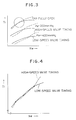
- Two sets of Ti map, one for the low-speed valve timing and the other for the high-speed valve timing, are prepared and stored in the electronic control circuit 7.
- the Ti value in the Ti map for the low-speed valve timing is indicated by a solid line curve while the Ti value in the Ti map for the high-speed valve timing is indicated by a dotted line curve.
- the intake air quantity tends to level off with the increase of Ne at the low-speed valve timing.
- the intake air quantity keeps on increasing further to eventually surpass that at the low-speed value timing as the charging efficiency increases with the increase of Ne, so that the Ti value for the low-speed valve timing and that for the high-speed valve timing come to coincide with each other at some point on the curves.
- the air intake quantity is the same whether at the low-speed or high-speed valve timing. So is the A/F ratio at this point. Therefore, the engine output is also practically the same at this point.
- the charging efficiency subtly fluctuates with the change of Ne. This fluctuation becomes more conspicuous in the range approaching the point at which the throttle opening ( ⁇ th) is fully open so that, as shown in Figure 4, the Ti value for the low-speed valve timing and that for the high-speed valve timing become equal to each other at a plurality of points. As will be discussed later, when the valve timing is changed over at one of these points where the Ti value for the low-speed valve timing and that for the high-speed valve timing become equal to each other, the valve timing changeover is more likely to cause a hunting especially in the range where the throttle opening is large, thus adversely affecting durability of the changeover mechanism 13.
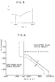
- the mixture is enriched according to the above-mentioned high-load fuel increase factor K WOT . Since a higher output can be brought about with the high-speed valve timing in this high-load region, a high-load determinant reference value T VT based on the fuel injection quantity is experimentally obtained as shown in Figure 5.
- a T VT value corresponding to Ne is calculated from a T VT table and when Tout is greater than T VT , the valve timing is changed over to the high-speed one as will be explained later.
- the Tout ⁇ T VT region includes regions in which, as discussed in the foregoing, the Ti values for the low-speed valve timing and the high-speed valve timing become equal to each other, the abovementioned hunting occurring with changeover of the valve timing can be prevented.
- a T VT table applicable to an automatic vehicle is different from that applicable to a manual vehicle.
- an allowable revolution speed of the engine should be different between the low-speed valve timing in which the valve-open duration is shorter and the high-speed valve timing in which the valve-open duration is longer, so that in this embodiment example the revolution limiter value is set at a comparatively lower one N HFC1 (for example, 7500 rpm) for the low-speed valve timing and at a comparatively higher one N HFC2 for example, 8100 rpm) for the high-speed valve timing.
- N HFC1 for example, 7500 rpm
- N HFC2 for example, 8100 rpm
- valve timing changeover characteristics a solid-line curve shows the changeover characteristic observed when the valve timing is changed over from the low-speed one to the high-speed one, while the dotted-line curve shows that observed when changing over in the opposite way.
- a valve timing changeover is performed in a region of the engine revolution speeds ranging between the lower-limit engine revolution speed Ne1 at which the engine output obtained with the low-speed valve timing always exceeds that obtained with the high-speed valve timing and the upper-limit engine revolution speed Ne2 at which the engine output obtained with the high-speed valve timing always exceeds that obtained with the low-speed valve timing.
- the valve timing changeover from the low-speed one to the high-speed one and vice versa are so set as to have a hysteresis; for example, Ne1 set at 4800 rpm/4600 rpm and Ne2 at 5900 rpm/5700 rpm.
- the region or range represented by X is one in which the valve timing changeover is performed through comparison of T VT with Tout while the region or range denoted by Y is one in which the valve timing changeover is performed through comparison made between a Ti value in the Ti map (hereinafter referred to as Ti L map) for the low-speed valve timing and a Ti value in the Ti map (hereinafter referred to as Ti map) for the high-speed valve timing.
- Ti L map Ti value in the Ti map
- Ti map Ti map
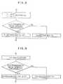
- Step 1 determines whether or not signals from the respective sensors are being normally inputted into the electronic control circuit 7 or, in other words, one for determining whether to start a fail-safe operation.
- Step 2 determines whether or not the engine is being started and step 3 determines whether or not the remainder time T ST of the delay timer has elapsed to 0.
- a time setting for T ST e.g. 5 seconds is performed in a step 4 during the engine starting so that the timing operation may start after the start of the engine.
- Step 5 determines whether or not the water temperature TW is lower than the present one TW1 (fort instance, 60°C), that is, whether or not the warming up of the engine has been achieved.
- Step 6 determines whether or not the vehicle speed V is lower than the present lowest vehicle speed V1 (for instance, 8 km/5km with a hysteresis), step 7 determines whether or not it is a manual vehicle (MT), step 8 determines, in case of an automatic vehicle (AT), whether the shift lever is set at the parking (P) position or the neutral (N) position, and step 9 determines whether or not Ne is greater than the above mentioned lower-limit value Ne1, so that when the fail-safe operation is going on or the engine is being started or the time preset with the delay timer has not elapsed as yet after the start of the engine, or warming up of the engine is going on, or the vehicle is parked or running at a slow speed, or the shift gear is set at P or N position, or Ne is smaller than Ne1, the electromagnetic valve 19 is closed to hold the valve timing set at the low-speed one as will be explained later.
- Ne is greater than the above mentioned lower-limit value Ne1
- the Ti L map and Ti H map are retrieved at a step 10 in order to obtain a Ti value in the Ti L map (said value being hereinafter referred to as Ti L ) and a Ti value in the Ti H map (said value being hereinafter referred to as Ti H ) which correspond to the current Ne and P B .
- Ti L Ti value in the Ti L map
- Ti H Ti value in the Ti H map
- this T VT is compared with Tout obtained previously (that is, Tout obtained in the immediately preceding round of operation) so as to determine whether or not it is Tout ⁇ T VT , that is, to determine whether it is in the high-load condition in which the mixture is enriched.
- Tout is smaller than T VT
- the program is advanced to step 13 for determining whether Ne is higher than the aforementioned upper-limit value Ne2 or not.
- Ne is smaller than Ne2
- the program is advanced to a step 14 to compare Ti L and Ti H with each other, both of which have been obtained at the step 10, and if Ti L is larger than Ti H (Ti L > Ti H ), a command or instruction to close the electromagnetic valve 19 is given out at a step 15, said instruction being tantamount to one to change over the valve timing to the low-speed one.
- Tout ⁇ T VT , Ne ⁇ Ne2, or Ti L ⁇ Ti H a command or instruction to open the electromagnetic valve 19, that is, an instruction to change over the valve timing to the high-speed one is given out in a step 16.
- a step 17 it is determined at a step 17 whether or not the hydraulic switch 20 has been turned on, that is, whether or not the oil pressure in the oil supplying passage 14 has been reduced to a lower level.
- the hydraulic switch 20 has been turned on, whether or not the remainder time t LVT for the low-speed valve timing changeover delay timer has been reduced to O is determined at a step 19.
- the remainder time t HVT for the high-speed valve timing changeover delay is set to a predetermined time (for example, 0.1 sec) at a step 21.
- a selection processing is performed to select the Ti L map as a Ti map for use with a fuel injection control routine, and the ignition timing map for the low-speed valve timing ( ⁇ igL map) as an ignition timing map, respectively.
- a processing is performed so as to turn the revolution limiter value N HFC to the value N HFC1 for the low-speed valve timing.
- step 18 When the instruction to open the valve has been given out at the step 16, it is determined at a step 18 whether or not the hydraulic switch 20 is turned off, that is, to determine whether or not the oil pressure in the oil supplying passage 14 has increased to a higher level.
- a selection processing is performed to select the Ti H map as a Ti map for use with the fuel injection control routine, and the ignition timing map for the high-speed valve timing( ⁇ igH) as an ignition timing map, respectively.
- a processing is performed so as to turn the revolution limiter value N HFC to the value N HFC2 for the high-speed valve timing.
- the time set with each of both the changeover delay timers described in the foregoing is predetermined so as to be adapted to the response delay time when the changeover mechanism 13 of each cylinder completes the required changeover operation as a result of the oil pressure change in the oil supplying passage 14.
- the program advances in order of 17-20-22-24-26 until the hydraulic switch 20 is turned on. Even with said switch turned on, the program is advanced in order of 17-19-24-26 until the changeover mechanism 13 of each cylinder has been turned to the low-speed valve timing side.
- the program is then advanced similarly in order of 17-20-22-24-26 as in the foregoing, indicating that unless the changeover mechanism 13 of each of all the cylinders has been turned to the low-speed valve timing side, the fuel injection remains so controlled as to be one suitable for the high-speed valve timing.
- the fuel injection should remain so controlled as to be one suitable for the low-speed valve timing in the like manner as above unless the changeover mechanism 13 of each of all the cylinders has been set to the high-speed valve timing side.
- the program is advanced to go from any of the steps 1 through 3 or 5 through 6 to the step 27 to give out an instruction to close the electromagnetic valve 19, and further advanced to go from the step 27 to the steps 21-23-25 in that order.
- the program is advanced to go from the step 8 to the step 28 in which whether or not the Ti H map has been selected previously is determined.
- the program is advanced to go from the step 9 to the step 29 at which a like determination or discrimination as made at the step 29 is carried out. If it is found that the Ti H map has not been selected previously, the program is advanced to go from the steps 28,29 to the step 15. If the Ti H map has not been selected previously for use, that is, when the changeover mechanism 13 of each of all the cylinders has not been set to the high-speed valve timing side, the program advances in order of 27-21-23-25 as in the foregoing so that the fuel injection may be controlled so as to be adapted to the low-speed valve timing irrespective of the hydraulic switch 20. This is a countermeasure designed to deal with the hydraulic switch in case the switch 20 should remain turned off due to breaking of its wiring.
- N HFC1 is set higher than Ne2.
- the valve timing is changed over to the high-speed one before Ne has increased to N HFC1 , causing the N HFC1 to be changed over to N HFC2 . Therefore, there is no fuel cut effect at N HFC1 .
- the low-speed valve timing is retained even when Ne comes to exceed Ne2 due to racing or the like so that a fuel cut is effected at N HFC1 .
- this fuel cut at N HFC1 goes on until t HVT becomes zero (0), that is, until the changeover mechanism 13 is actually set to the high-speed valve timing side, even after the low-speed valve timing has been changed over to the high-speed one.
- T VT to be used at the step 12 is one calculated from the T VT Table.
- a processing to subtract a predetermined amount of hysteresis ⁇ T VT from the calculated value is performed so as to use the balance as the T VT , and the changeover characteristic in the X region in Figure 6 is then added with the hysteresis.
Landscapes
- Engineering & Computer Science (AREA)
- Mechanical Engineering (AREA)
- General Engineering & Computer Science (AREA)
- Chemical & Material Sciences (AREA)
- Combustion & Propulsion (AREA)
- Output Control And Ontrol Of Special Type Engine (AREA)
- Valve Device For Special Equipments (AREA)
- Electrical Control Of Air Or Fuel Supplied To Internal-Combustion Engine (AREA)
Claims (4)
Voreinstellen eines Hochlastdeterminanten-Referenzwerts (TVT), der in Termen einer Kraftstoffeinspritzmenge berechnet ist, und
Umschalten der Ventilzeitsteuerung zu der Hochdrehzahl-Betriebsart, wenn eine Ist-Kraftstoffeinspritzmenge den Hochlastdeterminanten-Referenzwert übersteigt.
Feststellen mittels einer Bestätigungseinrichtung, ob die Ventilzeitsteuerung in den Zustand umgeschaltet worden ist, wie er vorliegen sollte, oder ob dies nicht der Fall ist, so daß wenn das Umschalten der Ventilzeitsteuerung nicht bestätigt wird, die Kraftstoffeinspritzung fortgesetzt werden kann, was eine Kraftstoffeinspritzung bewirkt, die aus der Standard-Kraftstoffeinspritzmenge für die Ventilzeitsteuerung, die vor dem neuen Umschaltbefehl ausgewählt wurde, bereicht ist.
Applications Claiming Priority (2)
| Application Number | Priority Date | Filing Date | Title |
|---|---|---|---|
| JP192240/88 | 1988-08-01 | ||
| JP63192240A JP2652879B2 (ja) | 1988-08-01 | 1988-08-01 | エンジンにおけるバルブタイミングの切換制御方法 |
Publications (2)
| Publication Number | Publication Date |
|---|---|
| EP0353863A1 EP0353863A1 (de) | 1990-02-07 |
| EP0353863B1 true EP0353863B1 (de) | 1992-01-02 |
Family
ID=16287988
Family Applications (1)
| Application Number | Title | Priority Date | Filing Date |
|---|---|---|---|
| EP89306638A Expired - Lifetime EP0353863B1 (de) | 1988-08-01 | 1989-06-29 | Steuerverfahren für die Ventilsteuerzeitumschaltung in einer Brennkraftmaschine |
Country Status (5)
| Country | Link |
|---|---|
| US (1) | US4917057A (de) |
| EP (1) | EP0353863B1 (de) |
| JP (1) | JP2652879B2 (de) |
| CA (1) | CA1326181C (de) |
| DE (1) | DE68900636D1 (de) |
Families Citing this family (17)
| Publication number | Priority date | Publication date | Assignee | Title |
|---|---|---|---|---|
| JP2712544B2 (ja) * | 1989-05-11 | 1998-02-16 | 日産自動車株式会社 | 車両用内燃機関のバルブタイミング制御装置 |
| JP2770238B2 (ja) * | 1989-06-15 | 1998-06-25 | 本田技研工業株式会社 | 内燃エンジンのバルブタイミング切換制御装置の故障検知方法 |
| JP2741266B2 (ja) * | 1989-12-18 | 1998-04-15 | マツダ株式会社 | エンジンの吸排気制御装置 |
| GB9003603D0 (en) * | 1990-02-16 | 1990-04-11 | Lotus Group Plc | Cam mechanisms |
| EP0515520B2 (de) * | 1990-02-16 | 1998-04-29 | Group Lotus Limited | Ventilsteuervorrichtung |
| US5253621A (en) * | 1992-08-14 | 1993-10-19 | Group Lotus Plc | Valve control means |
| JPH03260344A (ja) * | 1990-03-08 | 1991-11-20 | Honda Motor Co Ltd | 内燃エンジンの制御方法 |
| US5209201A (en) * | 1990-08-10 | 1993-05-11 | Honda Giken Kogyo Kabushiki Kaisha | Internal combustion engine |
| JP2687718B2 (ja) * | 1990-11-21 | 1997-12-08 | 日産自動車株式会社 | 内燃機関のカム切換制御装置 |
| JP2707832B2 (ja) * | 1990-11-26 | 1998-02-04 | 日産自動車株式会社 | 内燃機関の出力制御装置 |
| JPH04246249A (ja) * | 1991-01-31 | 1992-09-02 | Nissan Motor Co Ltd | 内燃機関の実圧縮比制御装置 |
| JP2905612B2 (ja) * | 1991-03-28 | 1999-06-14 | マツダ株式会社 | エンジンのバルブタイミング制御装置 |
| US5280770A (en) * | 1991-06-26 | 1994-01-25 | Honda Giken Kogyo Kabushiki Kaisha | Variable valve actuation control system |
| JP3286420B2 (ja) * | 1993-09-28 | 2002-05-27 | 株式会社ユニシアジェックス | 内燃機関の吸排気弁駆動制御装置 |
| JP2001214768A (ja) * | 2000-02-03 | 2001-08-10 | Fuji Heavy Ind Ltd | 可変バルブタイミング機構付エンジンの制御装置 |
| US7421981B2 (en) * | 2004-03-17 | 2008-09-09 | Ricardo, Inc. | Modulated combined lubrication and control pressure system for two-stroke/four-stroke switching |
| EP1788203B1 (de) * | 2005-11-18 | 2010-07-14 | Ford Global Technologies, LLC | Brennkraftmaschine mit einem Ventiltrieb mit variablem Ventilhub und Verfahren zur Steuerung des Ventilhubumschaltens |
Family Cites Families (11)
| Publication number | Priority date | Publication date | Assignee | Title |
|---|---|---|---|---|
| US4033304A (en) * | 1974-06-14 | 1977-07-05 | David Luria | Piston-type internal combustion engine |
| US4200067A (en) * | 1978-05-01 | 1980-04-29 | General Motors Corporation | Hydraulic valve actuator and fuel injection system |
| US4296911A (en) * | 1979-02-07 | 1981-10-27 | Escobosa Alfonso S | Hydraulic controlled sonic induction system |
| JPS58132173U (ja) * | 1982-03-01 | 1983-09-06 | トヨタ自動車株式会社 | エンジンの制御装置 |
| US4534323A (en) * | 1982-12-23 | 1985-08-13 | Nissan Motor Co., Ltd. | Valve operation changing system of internal combustion engine |
| JPH0639939B2 (ja) * | 1985-04-30 | 1994-05-25 | マツダ株式会社 | エンジンの動弁装置 |
| US4759321A (en) * | 1985-06-24 | 1988-07-26 | Nissan Motor Co., Ltd. | Valve timing arrangement for internal combustion engine having multiple inlet valves per cylinder |
| DE3619956A1 (de) * | 1986-06-13 | 1987-12-17 | Opel Adam Ag | Einrichtung zur automatischen drehwinkelverstellung einer nockenwelle von brennkraftmaschinen, insbesondere fuer kraftfahrzeuge |
| JPS63147909A (ja) * | 1986-10-23 | 1988-06-20 | Honda Motor Co Ltd | 内燃機関の弁作動特性可変制御装置 |
| US4807574A (en) * | 1986-12-27 | 1989-02-28 | Honda Giken Kogyo Kabushiki Kaisha | Valve operating device for internal combustion engine |
| JPS63167012A (ja) * | 1986-12-27 | 1988-07-11 | Honda Motor Co Ltd | 内燃機関用動弁機構の油圧回路 |
-
1988
- 1988-08-01 JP JP63192240A patent/JP2652879B2/ja not_active Expired - Lifetime
-
1989
- 1989-06-29 DE DE8989306638T patent/DE68900636D1/de not_active Expired - Lifetime
- 1989-06-29 EP EP89306638A patent/EP0353863B1/de not_active Expired - Lifetime
- 1989-06-30 CA CA000604598A patent/CA1326181C/en not_active Expired - Lifetime
- 1989-08-01 US US07/388,144 patent/US4917057A/en not_active Expired - Lifetime
Also Published As
| Publication number | Publication date |
|---|---|
| US4917057A (en) | 1990-04-17 |
| JP2652879B2 (ja) | 1997-09-10 |
| CA1326181C (en) | 1994-01-18 |
| JPH0242106A (ja) | 1990-02-13 |
| EP0353863A1 (de) | 1990-02-07 |
| DE68900636D1 (de) | 1992-02-13 |
Similar Documents
| Publication | Publication Date | Title |
|---|---|---|
| US5009203A (en) | Control method for valve-timing changeover in engine | |
| EP0353863B1 (de) | Steuerverfahren für die Ventilsteuerzeitumschaltung in einer Brennkraftmaschine | |
| EP0353862B1 (de) | Versagensfeststellungsverfahren für die Brennkraftmaschinen mit variabler Ventilsteuerung | |
| EP0359363B1 (de) | Methode zur Steuerung der Verstellung des Werkwinkels von Ventilen in Brennkraftmaschinen | |
| US4960083A (en) | Failsafe method in connection with valve timing-changeover control for internal combustion engines | |
| EP0399829B1 (de) | Verfahren zur Fehlererkennung bei einem Ventilzeitsteuerungssystem für eine innere Verbrennungskraftmaschine | |
| US4938188A (en) | Engine control apparatus | |
| US4960095A (en) | Knocking control system for internal combustion engines | |
| US6352061B2 (en) | Control device for a variable valve timing mechanism of an engine | |
| US4960094A (en) | Knocking control system for internal combustion engines | |
| US5709179A (en) | Engine cylinder valve control system | |
| US4938187A (en) | Fuel control apparatus for engine | |
| JP2733856B2 (ja) | 内燃エンジン及び変速機の連動制御装置 | |
| JP2630632B2 (ja) | 電子制御式燃料噴射型エンジンにおける燃料噴射制御方法 | |
| JP2637643B2 (ja) | 弁作動特性可変制御装置 | |
| JPS57206772A (en) | Ignition timing control method on internal combustion engine | |
| JP2679835B2 (ja) | エンジンの制御装置 | |
| JP2770236B2 (ja) | 自動変速機を備えた車輌の内燃エンジンのバルブタイミング制御方法 | |
| US5765526A (en) | Fuel supply control system for internal combustion engines | |
| JPH0716927Y2 (ja) | 車輌用自動変速機の制御装置 | |
| US4941556A (en) | Electronically-controlled fuel injection system for internal combustion engines | |
| JP2920808B2 (ja) | 内燃機関の燃料制御装置 | |
| JPH08105334A (ja) | 休筒エンジンの制御装置 | |
| JP2764863B2 (ja) | 自動変速機を備えた車輌の内燃エンジンのバルブタイミング制御方法 | |
| JPS61129453A (ja) | デイ−ゼル機関の低回転時排気ガス再循環制御方法 |
Legal Events
| Date | Code | Title | Description |
|---|---|---|---|
| PUAI | Public reference made under article 153(3) epc to a published international application that has entered the european phase |
Free format text: ORIGINAL CODE: 0009012 |
|
| AK | Designated contracting states |
Kind code of ref document: A1 Designated state(s): DE FR GB IT |
|
| 17P | Request for examination filed |
Effective date: 19900316 |
|
| 17Q | First examination report despatched |
Effective date: 19901004 |
|
| GRAA | (expected) grant |
Free format text: ORIGINAL CODE: 0009210 |
|
| AK | Designated contracting states |
Kind code of ref document: B1 Designated state(s): DE FR GB IT |
|
| REF | Corresponds to: |
Ref document number: 68900636 Country of ref document: DE Date of ref document: 19920213 |
|
| ITF | It: translation for a ep patent filed |
Owner name: MODIANO & ASSOCIATI S.R.L. |
|
| ET | Fr: translation filed | ||
| PLBE | No opposition filed within time limit |
Free format text: ORIGINAL CODE: 0009261 |
|
| STAA | Information on the status of an ep patent application or granted ep patent |
Free format text: STATUS: NO OPPOSITION FILED WITHIN TIME LIMIT |
|
| 26N | No opposition filed | ||
| REG | Reference to a national code |
Ref country code: GB Ref legal event code: IF02 |
|
| PGFP | Annual fee paid to national office [announced via postgrant information from national office to epo] |
Ref country code: GB Payment date: 20050629 Year of fee payment: 17 |
|
| PG25 | Lapsed in a contracting state [announced via postgrant information from national office to epo] |
Ref country code: GB Free format text: LAPSE BECAUSE OF NON-PAYMENT OF DUE FEES Effective date: 20060629 |
|
| GBPC | Gb: european patent ceased through non-payment of renewal fee |
Effective date: 20060629 |
|
| PGFP | Annual fee paid to national office [announced via postgrant information from national office to epo] |
Ref country code: IT Payment date: 20080625 Year of fee payment: 20 |
|
| PGFP | Annual fee paid to national office [announced via postgrant information from national office to epo] |
Ref country code: DE Payment date: 20080703 Year of fee payment: 20 |
|
| PGFP | Annual fee paid to national office [announced via postgrant information from national office to epo] |
Ref country code: FR Payment date: 20080617 Year of fee payment: 20 |