EP0353552A2 - Automatische Montage von Brücken und Rampen - Google Patents
Automatische Montage von Brücken und Rampen Download PDFInfo
- Publication number
- EP0353552A2 EP0353552A2 EP89113314A EP89113314A EP0353552A2 EP 0353552 A2 EP0353552 A2 EP 0353552A2 EP 89113314 A EP89113314 A EP 89113314A EP 89113314 A EP89113314 A EP 89113314A EP 0353552 A2 EP0353552 A2 EP 0353552A2
- Authority
- EP
- European Patent Office
- Prior art keywords
- segment
- bridge
- ramp
- base segment
- track
- Prior art date
- Legal status (The legal status is an assumption and is not a legal conclusion. Google has not performed a legal analysis and makes no representation as to the accuracy of the status listed.)
- Granted
Links
Images


Classifications
-
- E—FIXED CONSTRUCTIONS
- E01—CONSTRUCTION OF ROADS, RAILWAYS, OR BRIDGES
- E01D—CONSTRUCTION OF BRIDGES, ELEVATED ROADWAYS OR VIADUCTS; ASSEMBLY OF BRIDGES
- E01D15/00—Movable or portable bridges; Floating bridges
- E01D15/12—Portable or sectional bridges
- E01D15/127—Portable or sectional bridges combined with ground-supported vehicles for the transport, handling or placing of such bridges or of sections thereof
Definitions
- the present invention relates to an automatic-assembly bridge, ramp and the like.
- bridges, ramps or the like which can be installed in a relatively short time in case of natural disasters or military conflicts are already commercially available.
- Known bridges or ramps are generally provided by means of elements which mutually extend from one another and generally do not have sufficiently wide useful spans.
- the aim of the invention is indeed to eliminate the above described disadvantages by providing an automatic-assembly bridge, ramp and the like which can be easily transported on roads with a simple tractor for semi-trailers, thus making its transport to the installation site very easy and rapid.
- a particular object of the invention is to provide a bridge, ramp and the like which does not require external operating means for its assembly since it is automatically assembled, in that the elements which allow its unfolding are directly incorporated, allowing to install it in extremely short times, in the order of about ten minutes, without being substantially affected by the conditions of the installation site.
- Another object of the present invention is to provide a bridge, ramp and the like which can reach considerable useful lengths without creating dangerous conditions during the installation stage.
- Not least object of the present invention is to provide an automatic-assembly bridge, ramp and the like which by virtue of its peculiar constructive characteristics is capable of giving the greatest assurances of reliability and safety in use.
- an automatic-assembly bridge, ramp and the like characterized in that it comprises a base segment which has, on one face, at least one set of wheels provided with positioning means for disengaging from the ground when the bridge, ramp and the like is installed, and means for releasably coupling to a tractor, at least a second segment being articulated to one end of said segment, said second segment being constituted by a first track and by a second track which can be arranged mutually side by side and can be rotated independently from one another so as to be arranged in a transport position, wherein said tracks of said second segment are superimposed on said base segment, and in an installation position, wherein said tracks are arranged substantially along the extension of said base segment, one of said tracks being adapted to act as ballast during the rotation of the other.
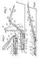
- the automatic-assembly bridge, ramp and the like comprises a base segment, generally indicated by the reference numeral 1, which is advantageously but not necessarily defined by two sections which are divided longitudinally so that they can be easily transported; during installation , the two sections are rigidly coupled to one another so as to form said base segment.
- Said base segment 1 may naturally also be provided monolithically.
- the base segment acts in practice as a mobile frame for road transport.
- two sets of four tires 2 each are provided at one end of the base segment, preferably the rear end. Said tires 2 are mounted on rockers 3 so that each wheel is independent from the others so as to ensure correct distribution of the weight on the wheel even on uneven ground.
- the two sets of wheels 2 are provided with an easily adjustable hydropneumatic suspension 4.
- the vertical positioning of the wheels is adjusted by means of hydraulic pistons 5 which act on the rocker-holder arm 6 so that the set of wheels can be raised or lowered as required and in particular so that it can be retracted at least partially within the base segment so as to disengage from the ground when the bridge or ramp is installed.
- the two rear wheels are equipped with pneumatic brakes, according to international norms, complete with all auxiliary elements.
- Compressed air is drawn from the tractor, and an auxiliary compressed air tank is furthermore accommodated in the base segment.
- Said base segment defines, at the other end but on the same face, an articulation 7 for its articulated coupling to the tractor 8.
- a tilt-down flap or skid 9 is pivoted at the front end of the base segment and has the function of facilitating the access of vehicles to the bridge by eliminating the difference in level on the access side which occurs due to the different inclinations which the bridge may assume.
- Said tilt-down flap is actuated by a front hydraulic piston 10 which is hinged or pivoted to the base segment at one end and, at the other end, to a gusset 11 rigidly associated with the tilt-down flap or skid 9.
- Hydraulic jacks 12 are provided at the front end of the base segment and have the function of lifting and supporting the base segment in its front part during the operations for uncoupling it from the tractor and for coupling it thereto.
- Rear stabilizers 13 are furthermore arranged proximate to the set of wheels 2 and can be extracted and lowered hydraulically from the base segment so as to ensure the necessary stability during the opening and closure of the segments, as will become apparent hereinafter, and to make sure the base segment rests properly on the ground when the bridge is in operating position.
- the base segment furthermore defines a seat for the accommodation of a hydraulic control unit 14 which supervises the operation of the bridge's hydraulic systems.
- the pipes directed toward the secondary hydraulic services are connected directly to the control unit, while the pipes for the primary services, i.e. those required to open and close the segment, are made of steel as regards the section provided inside the base segment and are then connected by means of very high-pressure flexible tubes to the successive segments where the opening and closure cylinders are provided.
- the base segment is pivoted at its rear end by means of large-size hinges 15 to a second segment, generally indicated by the reference numeral 20, which is defined by two tracks 20a and 20b which are arranged side by side along their longitudinal extension.
- Brackets 21 are provided at the rear end of the base segment, and tension elements 22 are articulated thereto; in turn, said elements are connected to sliding heads 23 of hydraulic cylinders for lifting the second segment which are indicated by 24 and are accommodated inside said second segment.
- the two tracks 20a and 20b can be folded over independently from one another by means of the hydraulic actuation of the lifting cylinder 24, which rotates each track of the second segment with respect to the base segment by means of the tension element provided between the head of the hydraulic cylinder 24 and the bracket 21.
- the hydraulic cylinder exerts a traction force, during a first rotation step, until the second segment arranges itself substantially vertically with respect to the base segment; once said second segment has become vertical, said cylinder acts as braking element until positioning is completed.
- This kind of coupling allows a mutual rotation of approximately 200 o about the hinge 15 which is provided by means of a single hydraulic cylinder for each track, as does not occur in the solutions of the known art.
- An end segment 30 is pivoted to the other end of the second segment and is also constituted by a first track 30a and by a second track 30b which are pivoted to the second segment by means of a second hinge 31.
- Each track of the third segment has a semi-circular element 31 rigidly associated therewith concentrically to the hinge 29; said semi-circular element has an accommodation for a metallic cable 32 which is connected to hydraulic cylinders 35 for rotating the third segment which are accommodated in the second segment.
- the two tracks of the third segment 30 are turned over by virtue of the hydraulic movement performed by means of the hydraulic piston 35.
- An important characteristic of the invention is constituted by the fact that one of the two tracks acts as ballast for the other track, i.e. during the step of installation of the bridge one track remains initially folded on the base segment while the other track is lifted, rotating it, by overturning the second arm with respect to the base segment and the third segment with respect to the second segment until they are arranged in the required position, as illustrated schematically in figures 7 to 10.
- an automatic-assembly bridge which includes all the means required for its unfolding and folding without having to resort to external lifting devices.
- Another characteristic aspect is furthermore constituted by the fact that the mutual rotation between the segments is obtained by means of hydraulic cylinders of appropriate size which act between one segment and the other.
- the materials employed may be any according to the requirements.
Landscapes
- Engineering & Computer Science (AREA)
- Architecture (AREA)
- Civil Engineering (AREA)
- Structural Engineering (AREA)
- Bridges Or Land Bridges (AREA)
- Table Devices Or Equipment (AREA)
- Executing Machine-Instructions (AREA)
- Medicines That Contain Protein Lipid Enzymes And Other Medicines (AREA)
- Load-Engaging Elements For Cranes (AREA)
- Forklifts And Lifting Vehicles (AREA)
- Control Of Motors That Do Not Use Commutators (AREA)
- Electric Double-Layer Capacitors Or The Like (AREA)
- Contacts (AREA)
- Flanged Joints, Insulating Joints, And Other Joints (AREA)
- Agricultural Machines (AREA)
- Guiding Agricultural Machines (AREA)
Priority Applications (1)
| Application Number | Priority Date | Filing Date | Title |
|---|---|---|---|
| AT89113314T ATE89625T1 (de) | 1988-08-02 | 1989-07-20 | Automatische montage von bruecken und rampen. |
Applications Claiming Priority (2)
| Application Number | Priority Date | Filing Date | Title |
|---|---|---|---|
| IT2162388 | 1988-08-02 | ||
| IT8821623A IT1226581B (it) | 1988-08-02 | 1988-08-02 | Ponte, rampa e simili di tipo automontante |
Publications (3)
| Publication Number | Publication Date |
|---|---|
| EP0353552A2 true EP0353552A2 (de) | 1990-02-07 |
| EP0353552A3 EP0353552A3 (en) | 1990-05-16 |
| EP0353552B1 EP0353552B1 (de) | 1993-05-19 |
Family
ID=11184469
Family Applications (1)
| Application Number | Title | Priority Date | Filing Date |
|---|---|---|---|
| EP89113314A Expired - Lifetime EP0353552B1 (de) | 1988-08-02 | 1989-07-20 | Automatische Montage von Brücken und Rampen |
Country Status (6)
| Country | Link |
|---|---|
| US (1) | US4972539A (de) |
| EP (1) | EP0353552B1 (de) |
| AT (1) | ATE89625T1 (de) |
| DE (1) | DE68906611T2 (de) |
| ES (1) | ES2041903T3 (de) |
| IT (1) | IT1226581B (de) |
Cited By (2)
| Publication number | Priority date | Publication date | Assignee | Title |
|---|---|---|---|---|
| EP2955274B1 (de) | 2014-06-10 | 2019-07-24 | General Dynamics European Land Systems-Bridge Systems GmbH | Transportierbare faltbare brücke |
| GB2574227A (en) * | 2018-05-31 | 2019-12-04 | Pearson Eng Ltd | Improvements in or relating to bridges |
Families Citing this family (8)
| Publication number | Priority date | Publication date | Assignee | Title |
|---|---|---|---|---|
| DE3911266A1 (de) * | 1989-04-07 | 1990-10-11 | Krupp Industrietech | Verlegbare bruecke und system zum verlegen der bruecke |
| US5697754A (en) * | 1996-02-20 | 1997-12-16 | Lincoln Industries Corp | Automatic ramp car with hydraulically powered elements |
| SE523664C2 (sv) * | 2002-09-25 | 2004-05-11 | Foersvarets Materielverk | Mobil bro och segment till en sådan bro |
| US6898815B2 (en) * | 2003-06-16 | 2005-05-31 | Cleone Young, legal representative | Portable unloading dock |
| DE102004049969B8 (de) * | 2004-10-14 | 2006-03-23 | Military Mobile Bridges Gmbh | Modulare Scherenbrücke sowie Verlegeeinrichtung und Verfahren zum Verlegen zerlegbarer Brücken |
| US7670096B2 (en) * | 2005-04-18 | 2010-03-02 | Grant Leum | Compound truck leveler |
| ES2335329B1 (es) * | 2007-04-20 | 2011-01-04 | Macgregor E.S.P., Sociedad Anonima | Rampa de tierra autopropulsada, para embarcar/desembarcar carga rodada en buques. |
| USD640854S1 (en) | 2010-08-19 | 2011-06-28 | Grant Leum | Hinged dock ramp |
Family Cites Families (8)
| Publication number | Priority date | Publication date | Assignee | Title |
|---|---|---|---|---|
| DE1019339B (de) * | 1956-06-04 | 1957-11-14 | Goeppner Kaiserslautern Eisen | Fahrbares, mit eigenem Antrieb versehenes Brueckenelement |
| DE1128452B (de) * | 1958-06-20 | 1962-04-26 | Hans Liebherr Fa | Vorrichtung fuer den Zusammenbau und zum Vorschieben der Teilabschnitte zerlegbarer Bruecken |
| US3105251A (en) * | 1958-09-12 | 1963-10-01 | Manning Maxwell & Moore Inc | Mobile bridge |
| FR1534033A (fr) * | 1967-06-15 | 1968-07-26 | Perfectionnements aux ponts militaires repliables et transportables | |
| FR2158618A5 (de) * | 1971-10-26 | 1973-06-15 | France Etat | |
| FR2281461A1 (fr) * | 1974-08-07 | 1976-03-05 | Gehlen Hermann | Element mobile de construction de pont |
| US4602399A (en) * | 1984-05-24 | 1986-07-29 | Harsco Corporation | Bridge transporting and launching trailer and method |
| GB8421616D0 (en) * | 1984-08-24 | 1984-09-26 | Secr Defence | Pickaback bridge spans |
-
1988
- 1988-08-02 IT IT8821623A patent/IT1226581B/it active
-
1989
- 1989-07-20 ES ES198989113314T patent/ES2041903T3/es not_active Expired - Lifetime
- 1989-07-20 DE DE8989113314T patent/DE68906611T2/de not_active Expired - Fee Related
- 1989-07-20 AT AT89113314T patent/ATE89625T1/de not_active IP Right Cessation
- 1989-07-20 EP EP89113314A patent/EP0353552B1/de not_active Expired - Lifetime
- 1989-07-25 US US07/385,017 patent/US4972539A/en not_active Expired - Fee Related
Cited By (4)
| Publication number | Priority date | Publication date | Assignee | Title |
|---|---|---|---|---|
| EP2955274B1 (de) | 2014-06-10 | 2019-07-24 | General Dynamics European Land Systems-Bridge Systems GmbH | Transportierbare faltbare brücke |
| GB2574227A (en) * | 2018-05-31 | 2019-12-04 | Pearson Eng Ltd | Improvements in or relating to bridges |
| GB2574227B (en) * | 2018-05-31 | 2023-02-01 | Pearson Eng Ltd | Improvements in or relating to bridges |
| US11613857B2 (en) | 2018-05-31 | 2023-03-28 | Pearson Engineering Limited | Bridges |
Also Published As
| Publication number | Publication date |
|---|---|
| DE68906611T2 (de) | 1993-09-02 |
| ATE89625T1 (de) | 1993-06-15 |
| IT8821623A0 (it) | 1988-08-02 |
| ES2041903T3 (es) | 1993-12-01 |
| US4972539A (en) | 1990-11-27 |
| EP0353552A3 (en) | 1990-05-16 |
| DE68906611D1 (de) | 1993-06-24 |
| EP0353552B1 (de) | 1993-05-19 |
| IT1226581B (it) | 1991-01-24 |
Similar Documents
| Publication | Publication Date | Title |
|---|---|---|
| CN103832310B (zh) | 车轮支撑悬置组件 | |
| US5350271A (en) | Automobile lifting and towing equipment | |
| US12162318B2 (en) | Vertical hi-rail device | |
| EP0353552B1 (de) | Automatische Montage von Brücken und Rampen | |
| US5475386A (en) | Portable folding standard and traffic signal apparatus | |
| EP0450942B1 (de) | Blockierungsmechanismus für ein Fahrzeug | |
| US4992788A (en) | Traffic control trailer system | |
| US4268208A (en) | Portable self-erecting silo apparatus | |
| US20070295497A1 (en) | Articulated mast for a coiled tubing rig | |
| JPH1087278A (ja) | 自走クレーン | |
| US5302076A (en) | Tow vehicle for maneuvering of vehicles | |
| US5192178A (en) | Extensible discharge chute assembly | |
| US5303946A (en) | Tag axle with rearwardly extending support framework | |
| US5018593A (en) | High lift tag axle for trucks | |
| US5302074A (en) | Wheeled vehicle for ground transport of aircraft | |
| GB2134052A (en) | Wheel suspension | |
| US4078684A (en) | Folding gooseneck trailer and method | |
| US4238003A (en) | Vehicle lift rack | |
| US6315311B1 (en) | Self-stowing wheeled support structure | |
| US4201022A (en) | Wheeled portable well drilling and workover apparatus | |
| US3633776A (en) | Hydraulically controlled flatbed trailer | |
| US4116467A (en) | Outrigger | |
| US4290731A (en) | Apparatus for picking up overturned vehicles | |
| JPH07115638B2 (ja) | 鉄道の保線車両の脱線回復装置 | |
| US20210281052A1 (en) | Mobile guard structure |
Legal Events
| Date | Code | Title | Description |
|---|---|---|---|
| PUAI | Public reference made under article 153(3) epc to a published international application that has entered the european phase |
Free format text: ORIGINAL CODE: 0009012 |
|
| AK | Designated contracting states |
Kind code of ref document: A2 Designated state(s): AT CH DE ES FR GB LI SE |
|
| PUAL | Search report despatched |
Free format text: ORIGINAL CODE: 0009013 |
|
| AK | Designated contracting states |
Kind code of ref document: A3 Designated state(s): AT CH DE ES FR GB LI SE |
|
| 17P | Request for examination filed |
Effective date: 19900517 |
|
| 17Q | First examination report despatched |
Effective date: 19910905 |
|
| GRAA | (expected) grant |
Free format text: ORIGINAL CODE: 0009210 |
|
| AK | Designated contracting states |
Kind code of ref document: B1 Designated state(s): AT CH DE ES FR GB LI SE |
|
| REF | Corresponds to: |
Ref document number: 89625 Country of ref document: AT Date of ref document: 19930615 Kind code of ref document: T |
|
| ET | Fr: translation filed | ||
| REF | Corresponds to: |
Ref document number: 68906611 Country of ref document: DE Date of ref document: 19930624 |
|
| REG | Reference to a national code |
Ref country code: ES Ref legal event code: FG2A Ref document number: 2041903 Country of ref document: ES Kind code of ref document: T3 |
|
| PLBE | No opposition filed within time limit |
Free format text: ORIGINAL CODE: 0009261 |
|
| STAA | Information on the status of an ep patent application or granted ep patent |
Free format text: STATUS: NO OPPOSITION FILED WITHIN TIME LIMIT |
|
| 26N | No opposition filed | ||
| PGFP | Annual fee paid to national office [announced via postgrant information from national office to epo] |
Ref country code: ES Payment date: 19940620 Year of fee payment: 6 |
|
| PGFP | Annual fee paid to national office [announced via postgrant information from national office to epo] |
Ref country code: SE Payment date: 19940623 Year of fee payment: 6 |
|
| PGFP | Annual fee paid to national office [announced via postgrant information from national office to epo] |
Ref country code: FR Payment date: 19940708 Year of fee payment: 6 |
|
| PGFP | Annual fee paid to national office [announced via postgrant information from national office to epo] |
Ref country code: GB Payment date: 19940712 Year of fee payment: 6 |
|
| PGFP | Annual fee paid to national office [announced via postgrant information from national office to epo] |
Ref country code: CH Payment date: 19940727 Year of fee payment: 6 |
|
| PGFP | Annual fee paid to national office [announced via postgrant information from national office to epo] |
Ref country code: AT Payment date: 19940729 Year of fee payment: 6 |
|
| PGFP | Annual fee paid to national office [announced via postgrant information from national office to epo] |
Ref country code: DE Payment date: 19940919 Year of fee payment: 6 |
|
| EAL | Se: european patent in force in sweden |
Ref document number: 89113314.2 |
|
| PG25 | Lapsed in a contracting state [announced via postgrant information from national office to epo] |
Ref country code: GB Effective date: 19950720 Ref country code: AT Effective date: 19950720 |
|
| PG25 | Lapsed in a contracting state [announced via postgrant information from national office to epo] |
Ref country code: SE Effective date: 19950721 Ref country code: ES Free format text: LAPSE BECAUSE OF EXPIRATION OF PROTECTION Effective date: 19950721 |
|
| PG25 | Lapsed in a contracting state [announced via postgrant information from national office to epo] |
Ref country code: LI Effective date: 19950731 Ref country code: CH Effective date: 19950731 |
|
| REG | Reference to a national code |
Ref country code: CH Ref legal event code: PL |
|
| GBPC | Gb: european patent ceased through non-payment of renewal fee |
Effective date: 19950720 |
|
| PG25 | Lapsed in a contracting state [announced via postgrant information from national office to epo] |
Ref country code: DE Effective date: 19960402 |
|
| EUG | Se: european patent has lapsed |
Ref document number: 89113314.2 |
|
| PG25 | Lapsed in a contracting state [announced via postgrant information from national office to epo] |
Ref country code: FR Effective date: 19960430 |
|
| REG | Reference to a national code |
Ref country code: FR Ref legal event code: ST |
|
| REG | Reference to a national code |
Ref country code: FR Ref legal event code: ST |
|
| REG | Reference to a national code |
Ref country code: FR Ref legal event code: ST |
|
| REG | Reference to a national code |
Ref country code: ES Ref legal event code: FD2A Effective date: 19990601 |