EP0353441A2 - Antennensteckdose - Google Patents
Antennensteckdose Download PDFInfo
- Publication number
- EP0353441A2 EP0353441A2 EP89111255A EP89111255A EP0353441A2 EP 0353441 A2 EP0353441 A2 EP 0353441A2 EP 89111255 A EP89111255 A EP 89111255A EP 89111255 A EP89111255 A EP 89111255A EP 0353441 A2 EP0353441 A2 EP 0353441A2
- Authority
- EP
- European Patent Office
- Prior art keywords
- housing
- insulating
- antenna
- bores
- connection
- Prior art date
- Legal status (The legal status is an assumption and is not a legal conclusion. Google has not performed a legal analysis and makes no representation as to the accuracy of the status listed.)
- Withdrawn
Links
Images
Classifications
-
- H—ELECTRICITY
- H02—GENERATION; CONVERSION OR DISTRIBUTION OF ELECTRIC POWER
- H02G—INSTALLATION OF ELECTRIC CABLES OR LINES, OR OF COMBINED OPTICAL AND ELECTRIC CABLES OR LINES
- H02G3/00—Installations of electric cables or lines or protective tubing therefor in or on buildings, equivalent structures or vehicles
- H02G3/02—Details
- H02G3/08—Distribution boxes; Connection or junction boxes
- H02G3/16—Distribution boxes; Connection or junction boxes structurally associated with support for line-connecting terminals within the box
-
- H—ELECTRICITY
- H01—ELECTRIC ELEMENTS
- H01R—ELECTRICALLY-CONDUCTIVE CONNECTIONS; STRUCTURAL ASSOCIATIONS OF A PLURALITY OF MUTUALLY-INSULATED ELECTRICAL CONNECTING ELEMENTS; COUPLING DEVICES; CURRENT COLLECTORS
- H01R4/00—Electrically-conductive connections between two or more conductive members in direct contact, i.e. touching one another; Means for effecting or maintaining such contact; Electrically-conductive connections having two or more spaced connecting locations for conductors and using contact members penetrating insulation
- H01R4/28—Clamped connections, spring connections
- H01R4/38—Clamped connections, spring connections utilising a clamping member acted on by screw or nut
- H01R4/42—Clamping area to one side of screw only
-
- H—ELECTRICITY
- H01—ELECTRIC ELEMENTS
- H01R—ELECTRICALLY-CONDUCTIVE CONNECTIONS; STRUCTURAL ASSOCIATIONS OF A PLURALITY OF MUTUALLY-INSULATED ELECTRICAL CONNECTING ELEMENTS; COUPLING DEVICES; CURRENT COLLECTORS
- H01R24/00—Two-part coupling devices, or either of their cooperating parts, characterised by their overall structure
- H01R24/38—Two-part coupling devices, or either of their cooperating parts, characterised by their overall structure having concentrically or coaxially arranged contacts
- H01R24/40—Two-part coupling devices, or either of their cooperating parts, characterised by their overall structure having concentrically or coaxially arranged contacts specially adapted for high frequency
- H01R24/52—Two-part coupling devices, or either of their cooperating parts, characterised by their overall structure having concentrically or coaxially arranged contacts specially adapted for high frequency mounted in or to a panel or structure
- H01R24/525—Outlets
Definitions
- the invention relates to an antenna socket for high frequencies with a pot-shaped box body made of metal, the wall of which has recesses for introducing the antenna-side connection cable and in which a connection and clamping piece with openings for these connection cables is arranged.
- antenna-side and receiver-side coaxial connections are made in antenna sockets of the type mentioned at the beginning.
- Coaxial connectors are provided for receiver connections, while the antenna-side connections can be detachably connected to the socket body by means of connecting and clamping pieces.
- Such antenna sockets are only conditionally suitable for high frequencies. This results in particular from the fact that the capacity of the antenna-side connections is very high.
- Another disadvantage with which the conventional antenna sockets, e.g. described in DE 35 30 721 A1 is that the connection and clamping pieces provided for the production of antenna-side connections consist of a large number of individual parts, which not only makes the production of the antenna-side connections more difficult but also time-consuming.
- the invention has for its object to further develop the generic antenna socket without undue design effort so that while simplifying the training the connection and clamping piece, the transmission of high frequencies is improved.
- the connecting and clamping piece is a housing which is integrally formed on the socket body and is open on the wall, into which an insulating body with connecting pins which run out in contact plates can be used for a printed circuit board which has bores open in the housing via the contact plates Has screwable clamping screws with insulating parts as well as holes opening into these bores and communicating with the openings for the connecting cables of the housing, into which the stripped ends of the connecting cables can be inserted and can be electrically conductively connected to the contact plates of the connecting pins by means of the insulating parts.
- the invention is achieved in any case if the connecting and clamping piece is formed as a part in which the connection between a printed circuit board and the antenna-side connecting cable can be produced by means of an insulating body with connecting pins, which goes from the bottom side of the socket body into the antenna socket is insertable.
- the housing is cuboid and the insulating body is complementary to the interior of the housing.
- tensioning screws cover the top side of the housing traverse and that the holes in the housing have threads for the clamping screws.
- the insulating body has a bore which runs transversely to the bores for the tensioning screws and into which a locking pin crossing the wall of the housing can be inserted.
- the tensioning screws serve to press the stripped ends of the connection cables against the connection pins, while a fixed connection between the housing and the insulating body can be produced by the locking pin.
- the locking pin extends transversely to the longitudinal axes of the clamping screws in order to be able to absorb the pressure exerted by the clamping screws on the insulating body. It is particularly expedient here if the locking pin passes through both the insulating body and the housing.
- the housing and the socket body are formed in one piece.
- each of the clamping screws consists of a threaded part and an insulating part which is in pressure connection with the end of the connecting cable.
- the insulating part has a section projecting into a blind hole in the threaded part and if the insulating part and the threaded part can be rotated relative to one another. It is thereby achieved that the insulating part exerts forces on the stripped end of the connecting cable which only extend in the axial direction of the clamping screws. Since the insulating part does not follow the rotating movements of the threaded part, the end of the connection cable is not twisted either.
- an expedient embodiment of the invention provides that the threaded part carries a radial sealing ring which is arranged between the threaded part and the insulating body.
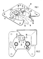
- an antenna socket for high frequencies is shown with a pot-shaped box body 10, the bottom 12 and wall 14 recesses 16 for the introduction of the antenna-side connection cables 18 and 19 and a connector and clamp 20 with openings 22 and 24 for this Has connection cables 18 and 19.
- the can body 10 can consist of a deep-drawn sheet metal part. On its open side, the can body 10 has a support ring 9 surrounding the pot in the manner of a ring, in which connecting bores 7 and 8 are formed. Two coaxial connection sockets 5 and 6 are used for connection at the receiving end.
- the connecting and clamping piece 20 consists of an open wall side Housing into which an insulating body 30 with pins 31 and 32 for a printed circuit board 34 can be inserted, the holes 36 and 38 for the housing, which pass through opening holes 36 and 38 for tensioning screws 40 and 41 as well as with these holes 36 and 38 and with the openings 22 and 24 for the connecting cables 18 and 19 of the housing communicating holes.
- the stripped ends 44 and 45 of the connecting cables 18 and 19 can be inserted into these bores and can be connected in an electrically conductive manner to the connecting pins 31 and 32 by means of the clamping screws 40 and 41.
- the connection pins 31 and 32 each have a contact plate 61 and 62 which lie snugly on the bottoms of the bores 36 and 38. If pressure is now exerted on the stripped ends 44 and 45 in the direction of the arrows 70 and 71, these are pressed against the contact plates 61 and 62 to produce an electrical connection.
- the housing is cuboid and the insulating body 30 is complementary to the interior of the housing.
- the clamping screws 40 and 41 pass through the cover side 50 of the housing.
- the bores 52 and 53 of the housing have threads for the clamping screws 40 and 41.
- the insulating body 30 has a bore 55 which extends transversely to the bores 52 and 53 for the tensioning screws 40 and 41 and into which a locking pin passing through the wall of the housing can be inserted.
- the locking pin passes through both the insulating body 30 and the housing.
- the housing and the can body 10 are formed in one piece.
- 3 shows that the clamping screw 40 from one Metallic threaded part 57 and an insulating part with the end 44 of the connecting cable 18 in pressure connection.
- the insulating part 58 has a section 59 projecting into a blind hole in the threaded part 57, so that the insulating part 58 and the threaded part 57 can be rotated relative to one another.
- the clamping screw 41 is also formed.
- the threaded part 57 carries a radial sealing ring 60, which is arranged between the threaded part 57 and the insulating body 30.
Landscapes
- Engineering & Computer Science (AREA)
- Architecture (AREA)
- Civil Engineering (AREA)
- Structural Engineering (AREA)
- Multi-Conductor Connections (AREA)
- Coupling Device And Connection With Printed Circuit (AREA)
Abstract
Die Erfindung betrifft eine Antennensteckdose für hohe Frequenzen mit einem topfförmigen Dosenkörper aus Metall, dessen Wandung Aussparungen zur Einführung der antennenseitigen Anschlußkabel besitzt und in dem ein Anschluß- und Klemmstück mit Öffnungen für diese Anschlußkabel angeordnet ist. Das Anschluß- und Klemmstückteil ist ein am Dosenkörper angeformtes und wandseitig offenes Gehäuse, in das ein Isolierkörper mit in Kontaktplatten auslaufenden anschlußstiften für eine Leiterplatte einsetzbar ist. Der Isolierkörper besitzt über den Kontaktplatten zum Gehäuse hin offene Bohrungen für im Gehäuse verschraubbare Spannschrauben mit Isolierteilen sowie in diese Bohrungen mündende und mit den Öffnungen für die Anschlußkabel des Gehäuses kommunizierende Bohrungen, in die die abisolierten Enden der Anschlußkabel einsteckbar und mittels den Isolierteilen mit den Kontaktplatten der Anschlußstifte elektrisch leitend verbindbar sind.
Description
- Die Erfindung betrifft eine Antennensteckdose für hohe Frequenzen mit einem topfförmigen Dosenkörper aus Metall, dessen Wandung Aussparungen zur Einführung der antennenseitigen Anschlußkabel besitzt und in dem ein Anschluß- und Klemmstück mit Öffnungen für diese Anschlußkabel angeordnet ist.
- In Antennensteckdosen der eingangs genannten Art werden sowohl antennenseitige als auch empfängerseitige koaxiale Anschlüsse hergestellt. Für Empfängeranschlüsse sind koaxiale Stecker vorgesehen, während die antennenseitigen Anschlüsse mittels Anschluß- und Klemmstücken mit dem Dosenkörper lösbar verbindbar sind. Solche Antennensteckdosen sind nur bedingt für hohe Frequenzen tauglich. Dies ergibt sich insbesondere aus der Tatsache, daß die Kapazität der antennenseitigen Anschlüsse sehr hoch ist. Ein weiterer Nachteil, mit dem die herkömmlichen Antennensteckdosen, wie sie z.B. in der DE 35 30 721 A1 beschrieben sind, behaftet sind, besteht darin, daß die für die Herstellung antennenseitiger Anschlüsse vorgesehenen Anschluß- und Klemmstücke aus einer Vielzahl von Einzelteilen bestehen, wodurch die Herstellung der antennenseitigen Anschlüsse nicht nur erschwert, sondern auch zeitaufwendig wird.
- Ausgehend von dem obigen Stand der Technik liegt der Erfindung die Aufgabe zugrunde, die gattungsgemäße Antennensteckdose ohne unangemessenen konstruktiven Aufwand so weiterzubilden, daß unter Vereinfachung der Ausbildung des Anschluß- und Klemmstückes die Übertragung hoher Frequenzen verbessert wird.
- Die gestellte Aufgabe wird erfindungsgemäß dadurch gelöst, daß das Anschluß- und Klemmstück ein am Dosenkörper angeformtes und wandseitig offenes Gehäuse ist, in das ein Isolierkörper mit in Kontaktplatten auslaufenden Anschlußstiften für eine Leiterplatte einsetzbar ist, der über den Kontaktplatten zum Gehäuse hin offene Bohrungen für im Gehäuse verschraubbare Spannschrauben mit Isolierteilen sowie in diese Bohrungen mündende und mit den Öffnungen für die Anschlußkabel des Gehäuses kommunizierende Bohrungen besitzt, in die die abisolierten Enden der Anschlußkabel einsteckbar und mittels den Isolierteilen mit den Kontaktplatten der Anschlußstifte elektrisch leitend verbindbar sind.
- Man erkennt, daß die Erfindung jedenfalls dann verwirklicht ist, wenn das Anschluß- und Klemmstück als ein Teil ausgebildet, bei dem die Verbindung zwischen einer Leiterplatte und dem antennenseitigen Anschlußkabel mittels eines Isolierkörpers mit Anschlußstiften herstellbar ist, der von der Bodenseite des Dosenkörpers in die Antennensteckdose einsteckbar ist.
- Weitere zweckmäßige und vorteilhafte Ausgestaltungen der Erfindung gehen aus den Unteransprüchen hervor.
- Bezüglich der Herstellung der Antennensteckdose ist es besonders zweckmäßig, wenn das Gehäuse quaderförmig und der Isolierkörper komplementär zum Innenraum des Gehäuses ausgebildet ist.
- Eine weitere zweckmäßige Ausgestaltung der Erfindung sieht vor, daß die Spannschrauben die Deckseite des Gehäuses durchqueren und daß die Bohrungen des Gehäuses Gewinde für die Spannschrauben aufweisen. Hierbei können diese Maßnahmen auch so getroffen sein, daß der Isolierkörper eine quer zu den Bohrungen für die Spannschrauben verlaufende Bohrung besitzt, in die ein die Wand des Gehäuses durchquerender Arretierstift einsteckbar ist. Die Spannschrauben dienen dazu, die abisolierten Enden der Anschlußkabel gegen die Anschlußstifte zu drücken, während durch den Arretierstift eine feste Verbindung zwischen dem Gehäuse und dem Isolierkörper herstellbar ist. Der Arretierstift erstreckt sich quer zu den Längsachsen der Spannschrauben, um den von den Spannschrauben auf den Isolierkörper ausübenden Druck auffangen zu können. Hierbei ist es besonders zweckmäßig, wenn der Arretierstift sowohl den Isolierkörper als auch das Gehäuse durchquert.
- Bezüglich der Herstellung der Antennensteckdose ist es besonders zweckmäßig, wenn das Gehäuse und der Dosenkörper einstückig ausgebildet sind.
- Eine weitere zweckmäßige Ausgestaltung der Erfindung sieht vor, daß jede der Spannschrauben aus einem Gewindeteil und einem mit dem Ende des Anschlußkabels in Druckverbindung stehenden Isolierteil besteht. Im Rahmen dieses Erfindungsgedankens ist es zweckmäßig, wenn das Isolierteil einen in eine Sacklochbohrung des Gewindeteiles hineinragenden Abschnitt besitzt und wenn das Isolierteil und das Gewindeteil gegeneinander verdrehbar sind. Dadurch wird erreicht, daß das Isolierteil auf das abisolierte Ende des Anschlußkabels Kräfte ausübt, die sich nur in axialer Richtung der Spannschrauben erstrecken. Da das Isolierteil den Drehbewegungen des Gewindeteils nicht folgt, wird auch das Ende des Anschlußkabels nicht verdreht.
- Schließlich sieht eine zweckmäßige Ausgestaltung der Erfindung vor, daß das Gewindeteil einen radialseitigen Dichtring trägt, der zwischen dem Gewindeteil und dem Isolierkörper angeordnet ist.
- Ein Ausführungsbeispiel der Erfindung ist in der Zeichnung schematisch dargestellt und wird im folgenden näher erläutert. Es zeigen:
- Fig. 1 einen Dosenkörper einer Antennensteckdose in perspektivischer Seitenansicht,
- Fig. 2 den in Fig. 1 dargestellten Dosenkörper in Draufsicht und
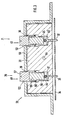
- Fig. 3 einen Schnitt entlang der Linie III-III nach Fig. 2.
- In den Fig. 1 und 2 ist eine Antennensteckdose für hohe Frequenzen mit einem topfförmigen Dosenkörper 10 dargestellt, dessen Boden 12 und Wandung 14 Aussparungen 16 zur Einführung der antennenseitigen Anschlußkabel 18 und 19 und ein Anschluß- und Klemmstück 20 mit Öffnungen 22 und 24 für diese Anschlußkabel 18 und 19 besitzt. Der Dosenkörper 10 kann aus einem tiefgezogenen Blechteil bestehen. An seiner offenen Seite weist der Dosenkörper 10 einen den Topf kranzartig umgebenden Tragring 9 auf, in dem Verbindungsbohrungen 7 und 8 ausgebildet sind. Zum empfangsseitigen Anschluß dienen zwei koaxiale Anschlußbuchsen 5 und 6.
- Wie insbesondere die Fig. 3 erkennen läßt, besteht das Anschluß- und Klemmstück 20 aus einem wandseitig offenen Gehäuse, in das ein Isolierkörper 30 mit Anschlußstiften 31 und 32 für eine Leiterplatte 34 einsteckbar ist, der zum Gehäuse hin offene Bohrungen 36 und 38 für das Gehäuse durchquerende Spannschrauben 40 und 41 sowie mit diesen Bohrungen 36 und 38 und mit den Öffnungen 22 und 24 für die Anschlußkabel 18 und 19 des Gehäuses kommunizierende Bohrungen besitzt. In diese Bohrungen sind die abisolierten Enden 44 und 45 der Anschlußkabel 18 und 19 einsteckbar und mit den Anschlußstiften 31 und 32 durch die Spannschrauben 40 und 41 elektrisch leitend verbindbar. Die Anschlußstifte 31 und 32 besitzen jeweils eine Kontaktplatte 61 und 62, die auf den Böden der Bohrungen 36 und 38 satt aufliegen. Wird nun in Richtung der Pfeile 70 und 71 Druck auf die abisolierten Enden 44 und 45 ausgeübt, dann werden diese gegen die Kontaktplatten 61 und 62 unter Herstellung einer elektrischen Verbindung gedrückt.
- Man erkennt, daß das Gehäuse quaderförmig und der Isolierkörper 30 komplementär zum Innenraum des Gehäuses ausgebildet ist. Die Spannschrauben 40 und 41 durchqueren die Deckseite 50 des Gehäuses. Die Bohrungen 52 und 53 des Gehäuses weisen Gewinde für die Spannschrauben 40 und 41 auf.
- Der Isolierkörper 30 besitzt eine quer zu den Bohrungen 52 und 53 für die Spannschrauben 40 und 41 verlaufende Bohrung 55, in die ein die Wand des Gehäuses durchquerender Arretierstift einsteckbar ist. Der Arretierstift durchquert sowohl den Isolierkörper 30 als auch das Gehäuse.
- Wie insbesondere Fig. 3 erkennen läßt, sind das Gehäuse und der Dosenkörper 10 einstückig ausgebildet. Ferner läßt die Fig. 3 erkennen, daß die Spannschraube 40 aus einem metallenen Gewindeteil 57 und einem mit dem Ende 44 des Anschlußkabels 18 in Druckverbindung stehenden Isolierteil besteht. Das Isolierteil 58 besitzt einen in eine Sacklochbohrung des Gewindeteils 57 hineinragenden Abschnitt 59, so daß das Isolierteil 58 und das Gewindeteil 57 gegeneinander verdrehbar sind. In gleicher Weise ist auch die Spannschraube 41 ausgebildet. Das Gewindeteil 57 trägt einen radialseitigen Dichtring 60, der zwischen dem Gewindeteil 57 und dem Isolierkörper 30 angeordnet ist.
Claims (8)
1. Antennensteckdose für hohe Frequenzen mit einem topfförmigen Dosenkörper aus Metall, dessen Wandung Aussparungen zur Einführung der antennenseitigen Anschlußkabel besitzt und in dem ein Anschluß- und Klemmstück mit Öffnungen für diese Anschlußkabel angeordnet ist,
dadurch gekennzeichnet,
daß das Anschluß- und Klemmstückteil (20) ein am Dosenkörper (10) angeformtes und wandseitig offenes Gehäuse ist, in das ein Isolierkörper (30) mit in Kontaktplatten (61,62) auslaufenden Anschlußstiften (31,32) für eine Leiterplatte (34) einsetzbar ist, der über den Kontaktplatten (61,62) zum Gehäuse hin offene Bohrungen (36,38) für im Gehäuse verschraubbare Spannschrauben (40,41) mit Isolierteilen (58) sowie in diese Bohrungen (36,38) mündende und mit den Öffnungen (22,24) für die Anschlußkabel (18,19) des Gehäuses kommunizierende Bohrungen besitzt, in die die abisolierten Enden (44,45) der Anschlußkabel (18,19) einsteckbar und mittels den Isolierteilen (58) mit den Kontaktplatten (61,62) der Anschlußstifte (31,32) elektrisch leitend verbindbar sind.
2. Antennensteckdose nach Anspruch 1,
dadurch gekennzeichnet,
daß das Gehäuse quaderförmig und der Isolierkörper (30) komplementär zum Innenraum des Gehäuses ausgebildet ist.
dadurch gekennzeichnet,
daß das Gehäuse quaderförmig und der Isolierkörper (30) komplementär zum Innenraum des Gehäuses ausgebildet ist.
3. Antennensteckdose nach Anspruch 1 oder 2,
dadurch gekennzeichnet,
daß die Spannschrauben (40,41) die Deckseite (50) des Gehäuses durchqueren und
daß die Bohrungen (52,53) des Gehäuses Gewinde für die Spannschrauben (40,41) aufweisen.
dadurch gekennzeichnet,
daß die Spannschrauben (40,41) die Deckseite (50) des Gehäuses durchqueren und
daß die Bohrungen (52,53) des Gehäuses Gewinde für die Spannschrauben (40,41) aufweisen.
4. Antennensteckdose nach einem der Ansprüche 1 bis 3,
dadurch gekennzeichnet,
daß der Isolierkörper (30) eine quer zu den Bohrungen (52,53) für die Spannschrauben (40,41) verlaufende Bohrung (55) besitzt, in die ein die Wand des Gehäuses durchquerender Arretierstift einsteckbar ist.
dadurch gekennzeichnet,
daß der Isolierkörper (30) eine quer zu den Bohrungen (52,53) für die Spannschrauben (40,41) verlaufende Bohrung (55) besitzt, in die ein die Wand des Gehäuses durchquerender Arretierstift einsteckbar ist.
5. Antennensteckdose nach Anspruch 4,
dadurch gekennzeichnet,
daß der Arretierstift sowohl den Isolierkörper (30) als auch das Gehäuse durchquert.
dadurch gekennzeichnet,
daß der Arretierstift sowohl den Isolierkörper (30) als auch das Gehäuse durchquert.
6. Antennensteckdose nach einem der Ansprüche 1 bis 5,
dadurch gekennzeichnet,
daß das Gehäuse und der Dosenkörper (10) einstückig ausgebildet sind.
dadurch gekennzeichnet,
daß das Gehäuse und der Dosenkörper (10) einstückig ausgebildet sind.
7. Antennensteckdose nach einem der Ansprüche 1 bis 6,
dadurch gekennzeichnet,
daß das Isolierteil (58) einen in eine Sacklochbohrung des Gewindeteiles (57) der Spannschraube (40) hineinragenden Abschnitt (59) besitzt und daß das Isolierteil (58) und das Gewindeteil (57) gegeneinander verdrehbar sind.
dadurch gekennzeichnet,
daß das Isolierteil (58) einen in eine Sacklochbohrung des Gewindeteiles (57) der Spannschraube (40) hineinragenden Abschnitt (59) besitzt und daß das Isolierteil (58) und das Gewindeteil (57) gegeneinander verdrehbar sind.
8. Antennensteckdose nach einem der Ansprüche 1 bis 7,
dadurch gekennzeichnet,
daß das Gewindeteil (57) einen radialseitigen Dichtungsring (60) trägt, der zwischen dem Gewindeteil (57) und dem Isolierkörper (30) angeordnet ist.
dadurch gekennzeichnet,
daß das Gewindeteil (57) einen radialseitigen Dichtungsring (60) trägt, der zwischen dem Gewindeteil (57) und dem Isolierkörper (30) angeordnet ist.
Applications Claiming Priority (2)
| Application Number | Priority Date | Filing Date | Title |
|---|---|---|---|
| DE19883826080 DE3826080C1 (de) | 1988-07-30 | 1988-07-30 | |
| DE3826080 | 1988-07-30 |
Publications (2)
| Publication Number | Publication Date |
|---|---|
| EP0353441A2 true EP0353441A2 (de) | 1990-02-07 |
| EP0353441A3 EP0353441A3 (de) | 1991-08-14 |
Family
ID=6360002
Family Applications (1)
| Application Number | Title | Priority Date | Filing Date |
|---|---|---|---|
| EP19890111255 Withdrawn EP0353441A3 (de) | 1988-07-30 | 1989-06-21 | Antennensteckdose |
Country Status (2)
| Country | Link |
|---|---|
| EP (1) | EP0353441A3 (de) |
| DE (1) | DE3826080C1 (de) |
Family Cites Families (2)
| Publication number | Priority date | Publication date | Assignee | Title |
|---|---|---|---|---|
| DE3327020A1 (de) * | 1983-07-27 | 1985-02-14 | Dietmar 7540 Neuenbürg Rosenberg | Antennensteckdose |
| DE3530721A1 (de) * | 1985-08-28 | 1987-03-05 | Kolbe & Co Hans | Antennensteckdose |
-
1988
- 1988-07-30 DE DE19883826080 patent/DE3826080C1/de not_active Expired
-
1989
- 1989-06-21 EP EP19890111255 patent/EP0353441A3/de not_active Withdrawn
Also Published As
| Publication number | Publication date |
|---|---|
| EP0353441A3 (de) | 1991-08-14 |
| DE3826080C1 (de) | 1989-11-16 |
Similar Documents
| Publication | Publication Date | Title |
|---|---|---|
| DE69735081T2 (de) | Elektrischer Mehrfachschnellverbinder | |
| DE69200695T2 (de) | Filterverbinder. | |
| DE69116000T2 (de) | Verbinder für Flachkabel mit mehreren Leitern | |
| EP0247662A1 (de) | Durchführungsanschluss für HF-Signale | |
| DE102018209360A1 (de) | Verbinder-verbindungs-struktur | |
| DE10334655A1 (de) | Steckverbindervorrichtung für Kleinservomotoren | |
| DE60310002T2 (de) | Geschirmte Steckeranordnung für die Datenübertragung | |
| DE19605083A1 (de) | Kabelanschlußeinrichtung | |
| DE102016109989A1 (de) | Steckverbinder | |
| DE3515910C2 (de) | ||
| EP0353441A2 (de) | Antennensteckdose | |
| EP0158586B1 (de) | Druck- oder Druckdifferenzmessgerät | |
| DE102021104729A1 (de) | Abschirmblech als Kontaktfeder in einem Steckverbinder | |
| DE2733200C3 (de) | Antennensteckdose | |
| DE3908532C2 (de) | ||
| DE60104219T2 (de) | Verbinder für ein Kabel und Bausatz für dessen Zusammenbau | |
| DE19525801A1 (de) | Vorrichtung zum elektrisch leitenden Verbinden von zwei elektrischen Leitungen | |
| DE8809761U1 (de) | Antennensteckdose | |
| DE2232322A1 (de) | Programmierbare schaltungsvorrichtung fuer flachdraht-flachkabelverbindungen | |
| DE3330327C1 (de) | Koaxial-Steckeinheit | |
| EP0163276B1 (de) | Antennensteckdose | |
| EP0930673A2 (de) | Transformationseinrichtung und Steckeranordnung | |
| DE3723791A1 (de) | Mehrpoliger steckverbinder fuer einbauzwecke | |
| DE69220605T2 (de) | Abgeschirmte rund-zu-flach Steckverbindungsanordnung | |
| DE619132C (de) | Laengsgeteilter Stecker |
Legal Events
| Date | Code | Title | Description |
|---|---|---|---|
| PUAI | Public reference made under article 153(3) epc to a published international application that has entered the european phase |
Free format text: ORIGINAL CODE: 0009012 |
|
| AK | Designated contracting states |
Kind code of ref document: A2 Designated state(s): AT BE CH DE ES FR GB GR IT LI LU NL SE |
|
| PUAL | Search report despatched |
Free format text: ORIGINAL CODE: 0009013 |
|
| AK | Designated contracting states |
Kind code of ref document: A3 Designated state(s): AT BE CH DE ES FR GB GR IT LI LU NL SE |
|
| STAA | Information on the status of an ep patent application or granted ep patent |
Free format text: STATUS: THE APPLICATION IS DEEMED TO BE WITHDRAWN |
|
| 18D | Application deemed to be withdrawn |
Effective date: 19910702 |