EP0353035A2 - Fremdstoffdetektor - Google Patents
Fremdstoffdetektor Download PDFInfo
- Publication number
- EP0353035A2 EP0353035A2 EP89307572A EP89307572A EP0353035A2 EP 0353035 A2 EP0353035 A2 EP 0353035A2 EP 89307572 A EP89307572 A EP 89307572A EP 89307572 A EP89307572 A EP 89307572A EP 0353035 A2 EP0353035 A2 EP 0353035A2
- Authority
- EP
- European Patent Office
- Prior art keywords
- values
- detector
- signal
- equation
- coefficients
- Prior art date
- Legal status (The legal status is an assumption and is not a legal conclusion. Google has not performed a legal analysis and makes no representation as to the accuracy of the status listed.)
- Granted
Links
Images


Classifications
-
- G—PHYSICS
- G01—MEASURING; TESTING
- G01V—GEOPHYSICS; GRAVITATIONAL MEASUREMENTS; DETECTING MASSES OR OBJECTS; TAGS
- G01V3/00—Electric or magnetic prospecting or detecting; Measuring magnetic field characteristics of the earth, e.g. declination, deviation
- G01V3/08—Electric or magnetic prospecting or detecting; Measuring magnetic field characteristics of the earth, e.g. declination, deviation operating with magnetic or electric fields produced or modified by objects or geological structures or by detecting devices
- G01V3/10—Electric or magnetic prospecting or detecting; Measuring magnetic field characteristics of the earth, e.g. declination, deviation operating with magnetic or electric fields produced or modified by objects or geological structures or by detecting devices using induction coils
- G01V3/104—Electric or magnetic prospecting or detecting; Measuring magnetic field characteristics of the earth, e.g. declination, deviation operating with magnetic or electric fields produced or modified by objects or geological structures or by detecting devices using induction coils using several coupled or uncoupled coils
- G01V3/105—Electric or magnetic prospecting or detecting; Measuring magnetic field characteristics of the earth, e.g. declination, deviation operating with magnetic or electric fields produced or modified by objects or geological structures or by detecting devices using induction coils using several coupled or uncoupled coils forming directly coupled primary and secondary coils or loops
- G01V3/107—Electric or magnetic prospecting or detecting; Measuring magnetic field characteristics of the earth, e.g. declination, deviation operating with magnetic or electric fields produced or modified by objects or geological structures or by detecting devices using induction coils using several coupled or uncoupled coils forming directly coupled primary and secondary coils or loops using compensating coil or loop arrangements
Definitions
- This invention relates to a detector for detecting in food products, pharmaceutical products, etc. the presence of materials such as metals, which must not be present in the product and which have a different quality from the inherent or standard quality of the actual product.
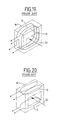
- This type of conventional detector includes an electromagnetic transducer as shown in Fig. 19 or 20, which is essentially the same as a differential transformer.
- the transducer has a primary or excitation coil 3 generating an alternating electromagnetic field when a high-frequency electrical current is supplied, and a pair of secondary or detection coils 4 and 5 electromagnetically connected to the coil 3.
- the secondary coils 4 and 5 are wound in opposite directions from each other and interconnected in series so that they operate differentially.
- the voltages or currents induced in the secondary coils cancel each other out or offset each other. This forms means for detecting the difference in the signals induced in the secondary coils.
- the primary coil 3 is wound between and coaxially with the secondary coils 4 and 5.
- the primary coil is wound in parallel planes with the secondary coils.
- the transducer utilizes the following phenomena which occur when an object being inspected is passed through the magnetic field in the direction 31.
- the magnetic flux density will increase.
- the induced voltage of the secondary coil 5 adjacent the passing object will first become higher than that of the other secondary coil 4. If the object contains a nonferrous metal, the eddy current occurring in the metal will cause a loss of the lines of magnetic force. As a result, the induced voltage of the secondary coil 5 will first become lower than that of secondary coil 4.
- Some food products may contain water or salt which may generate a relatively large signal, for reasons similar to those in the case of nonferrous metal, even though the products contain no foreign matter.
- This signal represents the product characteristics of the material, which are called "material effect”.
- the signal resulting from it will be small, and there is little difference between the signal generated by the product characteristics of the product itself and the combination of this signal and that caused by the foreign matter. This makes it difficult to detect the foreign matter.
- the oscillation signal from an oscillator is supplied via a phase shifter to a transducer 4, which outputs a differential signal when an object passes through the transducer.
- This output signal is detected by a first chopper synchronized with the oscillation signal to obtain an in-phase chopped signal, and by a second chopper having a phase difference of 90 degrees from the oscillation signal to obtain a quadrature chopped signal.
- Each chopped signal is filtered and independently compared by a level comparator.
- this detector to detect foreign matter in products having material effect, by adjusting one of the choppers to the phase at which the influence of the material effect is minimized (the phase 90 degrees from the phase angle at which the material effect is maximized), a detection signal with good sensitivity to the foreign matter can be obtained.
- the detector is adjusted as described above, it is necessary to give a large reference level in advance for offsetting the material effect for foreign matter producing a signal in the same direction as that of the material effect. Consequently, in this phase direction, the detector is used in a condition in which the sensitivity has been sharply reduced. Consequently, less detection effectiveness can be expected for metals and other foreign matter in this phase direction.
- the objective of this invention is to propose a detector for detecting the presence of metals and other foreign matter which does not require the operator to perform skilled trial-and-error adjustments such as the two factors of the phase adjustment and the sensitivity adjustment, and which is capable of detecting with good-sensitivity foreign matter having a phase direction the same as or close to that of the material effect.
- a detector comprises: means for providing a two-dimensional pair of analog signals representative of electromagnetic parameters of an object; means for converting said analog signals respectively into two series of digital values; means for determining a pair of representative values each among one of said series of digital values; and means for comparing said representative values with reference values.
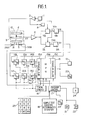
- an oscillator 1 generates a basic sine-wave electrical alternating current signal having a high frequency which is selectable within a range of 30 to 400 kHz.
- An electromagnetic transducer 10 is essentially the same as the conventional transducer shown in Fig. 19, and may otherwise be constructed as shown in Fig. 20.
- the transducer 10 has a primary coil 3 connected through a first terminal with the output of amplifier 2, and a pair of secondary coils 4 and 5 for providing a differential signal XY representative of electromagnetic parameters of an object being evaluated.
- a photoelectric sensor which may include a light emitter 26A and a light receiver 26B, is located in front of the secondary coil 5 to detect the passage of the object into the transducer 10.
- the output line of secondary coils 4 and 5 is connected through a second amplifier 6 with first inputs of a pair of multiplier/detectors 7A and 7B, which are essentially the same as the four-quadrant wave detectors or product detectors used in FM receivers.
- the wave detector 7A has a second input connected with the output of first amplifier 2 to receive the amplified signal as a reference signal in phase with the basic oscillation signal.
- the detector 7B has a second input connected through a phase shifter 8 with the output of first amplifier 2 to receive a reference signal out of phase, which is 90 degrees delayed from the basic signal.
- detectors 7A and 7B are connected through pairs of smoothers/filters 9A and 9B, sample-and-hold circuits 11A and 11B, analog/digital converters 12A and 12B and weighting circuits 14A and 14B with the input interface 15A of a control or computing device 15.
- the input interface 15A is connected with the light receiver 26B and a device 24 for inputting a region coefficient as explained later.
- the control device 15 includes a microprocessing unit (MPU) 15B and an output interface 15C, which is connected with an alarm 19, such as a lamp or buzzer emitting a warning indication when foreign matter is detected.
- MPU microprocessing unit
- the interface 15C is also connected with an R/ ⁇ indicator 20 indicating the magnitude and phase angle of the data.
- a timing control circuit 16 is connected with the sample-and-hold circuits 11A and 11B, A/D converters 12A and 12B, weighting circuits 14A and 14B and control device 15, to operate them in synchronization.
- a program control circuit 17 is connected with the control device 15, an execution (ON) button 21 which initiates operation of the control device 15, and a stop (OFF) button 22 which terminates it.
- the program control circuit 17 is also connected with a selector switch 18 for selecting one of the modes "sample test”, “equation determination” and “operation” and another switch 23 for selecting one of the sample modes "M" and "N” explained later.
- the program control circuit 17 is provided with a keyboard 25 to store data for a type of object and use it for subsequent inspections.
- the keyboard 25 has numeric keys for specifying a code number to label the type of object after collecting the data, a command key Mi for storing the data in the memory of MPU 15b, and a command key Mo for recalling it.
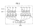
- the weighting circuits 14A and 14B each comprise a predetermined number of stages of delay elements 141, which are connected in cascade or series, and which may be a shift register.
- the inputs of elements 141 and the output of the last element are connected through coefficient multipliers 142, respectively, with a summer 143 such as a counter.
- the circuit of Fig. 2 is a non-recursive type circuit, and may be what is commonly known as an FIR (finite impulse response) filter.
- the weighting circuit may be replaced by, for example, a 16-bit microprocessor or a commercially available multiplier/accumulator designed for digital computations.
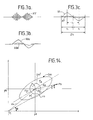
- the differential signal XY is amplified by the second amplifier 6, and-then detected by the wave detectors 7A and 7B by multiplication by the in-phase and out-of-phase reference signals, respectively.
- the detectors 7A and 7B output signals Xde and Yde in waveforms as shown in Fig. 3b.
- the detected signal Xde corresponds to the component of differential signal XY which is in phase with the basic oscillation signal, while the signal Yde corresponds to the component of signal XY which has a 90 degree phase delay from the basic signal.
- the detected signals Xde and Yde are filtered by the associated smoothers/filters 9A and 9B to be signals Xf and Yf with waveforms as shown in Fig. 3c, which are temporarily stored in the corresponding sample-and-hold circuits 11A and 11B.
- the stored analog signals are converted to digital signals Xdi and Ydi by the corresponding A/D converters 12A and 12B at regular intervals, and input to the corresponding weighting circuits 14A and 14B, which perform weighting processing characterized by a time distribution as will be explained in detail below.
- the signal Xdi for example, as a discrete series of digital values x(0), X(T) ... X((n-1)T) is input to the weighting circuit 14A at sample time intervals T. (For convenience, this explanation uses zero as the time of the first value X(0).)
- Each weighting circuit 14A, 14B has a pulse transfer function for weighting which is a series expressed as a polynomial relating to Z ⁇ 1 to the order n-1, the number n being odd, as shown in the following Equation (1).
- H(z) K0 + K1z ⁇ 1 + K2Z ⁇ 2 + ... K n-1 Z -(n-1) (1)
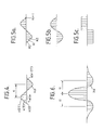
- the number n of multipliers 142 are assigned weighting coefficients Ko to Kn-1 which are distributed in the form of an odd function, as shown in Fig. 5a, 5b or 5c.
- the coefficients have a point-symmetrical distribution, and the central coefficient for the central multiplier 142 is located at the origin point of the odd function.
- Fig. 5a The triangular distribution of Fig. 5a is the reverse form of a typical waveform, which resembles Fig. 4, representing the signal change with time when iron passes through the transducer 10.
- the number n is determined experimentally according to the duration of the typical wave.
- the distribution of Fig. 5b takes the form of a doublet sine wave, and that of Fig. 5c is rectangular.
- the duration of function H(z) is most preferably substantially the same as the period for which a typical material, such as iron, passes through the transducer 1.
- a digital signal with the polarities shown in Fig. 4 input to the weighting circuit 14A or 14B will produce a weighted signal as shown in Fig. 6, which has the following characteristics:
- the output signal from the weighting means, to which an input signal such as shown in Fig. 4 is applied has the characteristics of a discrete time-series output signal, which is distributed in the form of an even function with the origin point having the maximum value, if the time at which the time-series weighted signal has the maximum value is defined as the origin point of time.
- the digital signal Xdi for example, has a form with two polarities, positive and negative (or negative and positive), for a single object.
- the signal Xdi will have four peaks P1′-P4′.
- a pair of peaks P1′ and P2′ and a pair of peaks P3′ and P4′ should be identified separately for the respective products.
- the weighted signal Xw can be correctly identified for the different products, because the peaks P1 ⁇ and P3 ⁇ correspond respectively to the pair P1′-P2′ and the pair P3′-P4′ in Fig. 7a.
- the signals can always be identified for the respective products.
- the MPU 15B has a program, as shown in Fig. 8, to determine or recognize "primary values" out of the weighted signals Xw and Yw.
- the primary values represent the electromagnetic characteristics of an object being inspected.
- the monitoring span should be three to five times the time interval t1 of the two peaks which occur when foreign matter generates a signal, as shown in Fig. 3c or 4.
- an appropriate number 2n + 1 of weighted values Xw obtained during a specified time span are constantly monitored.
- the values Xw are stored in order from the newest data to the oldest data as Xi to Xi-2n in a series of memory addresses O-2n.
- Table 1 Address 0 1 2 ... n ... 2n Data Xi Xi-1 Xi-2... Xi-n ... Xi-2n
- Xi-n is determined as the primary value Xp. If there is, Yi-n and Yi-n+ ⁇ which have the same addresses as those of Xi-n and Xi-n+ ⁇ are compared. If Yi-n ⁇ Yi-n+ ⁇ (step 4), Xi-n is determined to be the primary value Xp, and the corresponding value Yi-n is determined to be the primary value Yp for the weighted signal Yw.
- Yi-n+ ⁇ is found to be larger than Yi-n, Xi-n is not determined to be the primary value. If this occurs, when Yi-n+ ⁇ is shifted to the central address n later, that value becomes the maximum value and is thus determined to be the primary value Yp.
- the primary values can be obtained without weighting.
- a positionally adjustable photoelectric or other type of sensor 50 (having an operating time different from that of sensor 26A, 26B in Fig. 1) is provided at an appropriate interval L lengthwise along a belt conveyor 51 with respect to the center of primary coil 3.
- the position and operating time of sensor 50 are preadjusted so that the signal Q generated by the sensor is ON for the time t1 corresponding to one half (e.g. the first half) of the undulating waveform of filtered signals Xf and Yf generated when the object is passed through the coils by the conveyor 51, beginning from the rise of the signal and continuing until the signal reaches the maximum value and then falls past the zero point.
- one half e.g. the first half
- the signals Xf and Yf are input to AND circuits 100 as shown in Fig. 11 together with the passage signal Q, so that the signals Xf and Yf can be detected only while the signal Q is ON. As shown in Figs. 12a and 12b, only the first halves of signals Xf and Yf are detected as signals in the form of a solitary wave similar to the weighted signals.
- these signals are converted to digital signals, and primary values can be obtained from the digital signals in the same way as for the weighted signals.
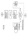
- the MPU 15B has a program for judgement or identification as shown in Fig. 18, which will be explained later.
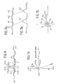
- Fig. 13 shows vectors representing the primary values Xp and Yp for various materials along the x and y axes, respectively.
- phase angle of the vector for iron is generally delayed approximately 90 degrees from that of the oscillation signal, and its absolute value or output sensitivity is high.
- the y component of the signal for iron is larger in absolute value than the x component.
- phase difference of the vectors for stainless steel (SUS) with respect to the oscillation signal is not very large.
- SUS1 Fig. 13
- both components are positive values.
- the x and y components are respectively positive and negative values.
- Some types of materials generate lagging signals like that of iron, and others generate leading signals.
- the material effect generally has characteristics and a phase angle which are peculiar to each individual product. Although the size of the vector will change with the content volume of the product, the phase angle will usually not change very much.
- points P1 (Xp1, Yp1), P2 (Xp2, Yp2), etc. represent the primary values Xp and Yp for various volumes of products of the same type which have material effect, but which contain no foreign matter.
- the primary values for a product having material effect and containing even minute particles of foreign matter, such as iron, will be represented at a point Pa (Xa, Ya) as a vector ra. Subtraction of vector rs from vector ra gives a deviation vector Ra from the average point Po.
- the region Dm defines the distribution boundary for products without foreign matter, and data such as point Pa outside this region are judged to represent products which contain foreign matter.
- these products are represented as points P1, P2, etc. within a circular region Dn on the graph.
- the central average point Po of region Dn is extremely close to the origin point 01.
- the region Dn is extremely smaller than for products having material effect.
- the size of the deviation vector Ra is approximately the same as that of the signal vector ra. Because of the small size of region Dn, even if the absolute values of these vectors are relatively small, they will extend beyond region Dn. It is thus possible to detect even more minute particles of foreign matter than for products having material effect.
- a passage signal is generated for a period of time corresponding to the time, 2t1 (Fig. 3c) which is the sum of time t1 preceding the passage of the center of the primary coil 3 by the object and time t1 following it.
- this passage signal is being generated, pairs of weighted values Xw and Yw are extracted as "N" mode sample data Xsn and Ysn, respectively, at intervals of a certain number of samples from among the continuous weighted values. For example, 10 to 20 weighted values are extracted for one packaged object.
- These values Xsn and Ysn may be represented by points P1-P4 in Fig. 15.
- the sample values Xsn and Ysn are also random with regard to a time series. It is possible to appropriately extract the characteristics of the amplitude, distribution, etc. of the original random signals from the many data signals obtained by extracting at certain intervals as described above.
- sample values Xsm and Xsn of the M and N modes are generally referred to as a sample value Xs hereinafter, and the values Ysm and Ysn as a sample value Ys.
- sample values Xs and primary values Xp are generally termed representative values X hereinafter, and Ys and Yp as representative values Y.
- a correlation coefficient ⁇ as a factor representing the correlation of values X and Y is included in discriminant equation (5), which determines the region and will be explained later.
- the weighted signals Xw and Yw have the characteristics of noise, that is, the sizes and phase of the signals are random and mutually unrelated, as shown in Fig. 15 and explained earlier, when the two-dimensional pairs of representative values X and Y extracted at random from weighted values Xw and Yw, respectively, are plotted on the coordinate system, they are distributed in an approximately circular region.
- the correlation coefficient ⁇ is a value approaching zero.
- the discriminant equation which determines the region can be established as a discriminant equation for an elliptical region which includes correlation.
- the region can be more narrowly defined than if correlation is not taken into consideration, and defective products which were mistakenly judged to be non-defective when correlation was previously not taken into consideration can be correctly judged to be defective, thus resulting in more accurate judgements.
- the introduction of the concept of correlation improves the capacity to judge the presence of foreign matter.
- the sample test used to determine the coefficients etc. of the equation is done in the M or N mode. In this test, a large number of pairs of sample data Xs and Ys are obtained, stored in the memory of MPU 15B, and used to compute each of the following values (data for the equation).
- ⁇ X average value of Xs
- ⁇ Y average value of Ys
- ⁇ x standard deviation regarding Xs
- ⁇ y standard deviation regarding Ys
- ⁇ xy covariance regarding Xs and Ys
- correlation coefficient expressed as
- the primary values Xp and Yp are used to compute a predetermined discriminant equation, and judgement concerning the presence of foreign matter is made on the basis of whether or not the equation is satisfied.
- the equation is described below.
- Equation (4) which is one example of the statistical distribution functions found in reference works on statistics, is used as the density function of the statistical distribution of the data. This equation works both for inspection objects which have material effect and for those which do not, as long as the data is considered to be from the same population.
- D the part of the above Equation (4) concerning the exponent of the equation.
- This D is a numerical value which determines the region, and it may be determined either based on empirical data, or by the following equation which uses correlation coefficient ⁇ and the region coefficient d which will be explained later.
- Equation (5) is the basic discriminant equation for determining the region.
- the region coefficient "d" in the above Equation (5) is input by the region coefficient setting device 24 shown in Fig. 1, which is the input device for this embodiment.
- this coefficient d is as follows.
- This coefficient d can be appropriately selected by the operator in association with the confidence value.
- the correlation coefficient ⁇ is calculated and the region coefficient d is selected by the operator, the value of "D", which determines the region, is determined.
- Equation (5) can be rewritten as the following Equations (8) and (8)'.
- A(X - ⁇ X)2 + B(X - ⁇ X)(Y - ⁇ Y) + C(Y - ⁇ Y)2 D (8)
- Equation (8) determines the boundary of the distribution region
- Equation (8)′ is the discriminant equation which judges whether or not the data is included in the region.
- Equation (8) defines an elliptical or circular region, depending on the value of the correlation coefficient ⁇ , it is applicable to both products which have material effect and those which do not.
- Equation (8)′ is included in the MPU 15B in the form of a program, and computed for each pair of primary values Xp and Yp at final inspection of objects.
- the region discriminant equation can be determined by the operator selecting and inputting appropriate values A, B and C, and the region coefficient d in accordance with the characteristics of the object.
- A, B and C the region discriminant equation
- the MPU 15B has a program whereby, when the operator uses the switch 18 to select the equation computation mode, the data which was obtained and stored in the previous sample test is recalled, the statistical quantities ⁇ X, ⁇ Y, ⁇ x, ⁇ y, ⁇ , etc. are automatically computed, and the values A, B and C are also automatically computed.
- the program further computes the value D in Equation (8) with these computed results when the region coefficient d is input by the operator via the device 24. This determines all coefficients of discriminant Equation (8)′ to specify this equation. In this way, the automatic setting for the region discriminant Equation (8)′ is completed.
- Equations (5a) and (8a) can be used in place of the Equations (5) and (8).
- Equation (5a) can be used to determine the following Equation (8a)′ as the discriminant equation.
- Equation (8a)′ A′(X - ⁇ X)2 + .C′(Y - ⁇ Y)2 - D′ ⁇ 0 (8a)′
- the inspection objects are of an approximately constant volume or fixed size, such as packaged products, when the measurement data (primary values) P1-P4, etc. of a typical inspection object are plotted on an x-y coordinate system, they are gathered together in the vicinity of a specific location on the coordinate system, as shown in Fig. 17.
- Equation (5b) and (5c) can be transformed to obtain the following Equations (8b)′ and (8c)′.
- Equations (8b)′ and (8c)′ are the discriminant equations, and objects which satisfy both of these equations are non-defective products containing no foreign matter. On the other hand, objects which fail to satisfy either one or both of these equations are judged to be defective products containing foreign matter.
- An illustration of the region determined by these equations appears as a region enclosed within a rectangle, as shown in Fig. 17. In other words, non-defective and defective products fall respectively in and outside the region.
- the distance between the central point Po of the region and the origin point 01 of the coordinate system represents the average size of the material effect of the product.
- these points Po and 01 are the same.
- Discriminant equations (8b)′ and (8c)′ are also programmed in the control device 15.
- the correlation coefficient ⁇ is also not taken into consideration for this third embodiment.
- the values Dx and Dy may also be empirical values.
- the operator operates the following devices: the device 24 to specify the region coefficient d; the numeric keys of keyboard 25 (Fig. 1) to specify the code number for the type of object; the command key Mi of keyboard 25 to input and store in the MPU 15B with the code number the various coefficients, such as A-D for the first embodiment, A′, C′ and D′ for the second embodiment, or Dx and Dy for the third embodiment, and the statistical quantities ⁇ X and ⁇ Y of the discriminant equation/s computed with the data obtained from the sample test results and with the coefficient d input by the operator; and the command key Mo to recall with the code number the data when the same discriminant equation is to be used on a subsequent occasion.
- the operator sets the selector switch 18 to the sample test mode.
- the R/ ⁇ indicator 20 is set to indicate the absolute value r and phase angle ⁇ of a vector r from the origin point on the coordinate system (Fig. 14, 15).
- the operator is able to continuously monitor the indication values during no-load operation and the subsequent sample test.
- a no-load test operation is performed to find the noise level of the apparatus itself on the indicator 20.
- the operator selects a number of samples, which have been determined to be free of foreign matter, from a type of objects to be inspected. He puts the samples to be passed through the coils, reads the absolute values on the indicator 20, and determines whether or not the values have increased from those during the no-load operation.
- the operator sets the selector switch 23 to either the M or N mode, presses the execution button 21, selects a large number of samples having no foreign matter from that type of objects, and puts the samples to be passed through the coils. As a result, regardless of which mode was used, the data for the samples is stored in the MPU 15B.
- Equation (8) the equations for the values A, B and C are then calculated to determine the coefficients for the left side of Equation (8).
- equations (8a)′ or (8b)′ and (8c)′ are determined likewise.
- the values D, D′ Dx, Dy, etc. can be found by calculating as explained, or, if empirical values are known, they can be input directly.
- the operator stores the values A, B, C, D, ⁇ X, ⁇ Y, etc. for the particular discriminant equation by inputting the code number for the type of objects via the keyboard 25 and then pressing its memory key Mi, and recalls the data when needed by inputting the same code number and then pressing the key Mo.
- the R/ ⁇ indicator 20 is set to indicate the absolute value R and phase angle ⁇ of a deviation vector R, which are computed by Equations (11) and (12) below with the primary values Xp and Yp.
- the program control circuit 17 inputs the program for inspection of objects to the MPU 15B.
- the judgement section of MPU 15B receives the data in the M mode.
- the values ⁇ X and ⁇ Y are the average sample values obtained in the sample test in the M or N mode, and the values A-D, or A′, C′ and D′, or Dx and Dy in the discriminant equation/s (8)′, (8a)′, or (8b)′ and (8c)′ have been predetermined in the preliminary procedures.
- the equation/s is/are then computed with the values Xp and Yp substituted for X and Y, respectively. If the result satisfied the equation (i.e., the left side is 0 or negative), the data is judged to be in the region. If the equation is not satisfied, the data is judged to be outside of the region.
- the alarm 19 is activated to warn that the object has not passed the inspection, and a sorting device (not shown) further down the line is commanded to remove the object.
- this method when an object contains water, salt or the like and has a material effect, if the amount of the contained material varies, the electromagnetic characteristics will change and the region conditions of the reference object (standard product) will not be satisfied. This will cause a signal which indicates that the object is defective to be generated. Thus, this method may be effective for use in quality control.
- the R/ ⁇ indicator 20 may be adapted to indicate the type of material effect of the object, or the type of foreign matter (metal, iron or non-ferrous metal, etc.) which has been detected in the object, as shown in Fig. 13.
- the detection signals contain not only data on whether or not foreign matter is present, but also quantitative data as well, the detection of foreign matter or of quality differences is easily accomplished.
- this detector it is also possible to detect instances where the quality of the product differs from the specified level.
- the detector can be provided at a lower cost than the prior detectors described herein, and maintenance and adjustments can be easily performed.
- the detection signals are expressed by two coordinates (i.e., in a two-dimensional plane) the type and size of metal can be easily identified, and even foreign matter which generates no more than a small signal can be detected.
Applications Claiming Priority (2)
| Application Number | Priority Date | Filing Date | Title |
|---|---|---|---|
| JP63185771A JPH0619470B2 (ja) | 1988-07-26 | 1988-07-26 | 金属等の異物混入検出方法および検出器 |
| JP185771/88 | 1988-07-26 |
Publications (3)
| Publication Number | Publication Date |
|---|---|
| EP0353035A2 true EP0353035A2 (de) | 1990-01-31 |
| EP0353035A3 EP0353035A3 (de) | 1991-03-20 |
| EP0353035B1 EP0353035B1 (de) | 1994-04-13 |
Family
ID=16176602
Family Applications (1)
| Application Number | Title | Priority Date | Filing Date |
|---|---|---|---|
| EP89307572A Expired - Lifetime EP0353035B1 (de) | 1988-07-26 | 1989-07-25 | Fremdstoffdetektor |
Country Status (5)
| Country | Link |
|---|---|
| US (1) | US5045789A (de) |
| EP (1) | EP0353035B1 (de) |
| JP (1) | JPH0619470B2 (de) |
| AU (1) | AU3896189A (de) |
| DE (1) | DE68914537T2 (de) |
Cited By (12)
| Publication number | Priority date | Publication date | Assignee | Title |
|---|---|---|---|---|
| US5189366A (en) * | 1988-12-20 | 1993-02-23 | Loma Group Limited | Method and apparatus using a varying electromagnetic field for determining the nature, or a property of a non-metallic material |
| GB2262606A (en) * | 1991-12-16 | 1993-06-23 | Radiodetection Ltd | Metal detector with nulling coil. |
| EP0949514A2 (de) * | 1998-04-07 | 1999-10-13 | Ishida Co., Ltd. | Fremdstoffdetektor und Fremdstofferfassungssystem |
| EP1065529A2 (de) * | 1999-06-30 | 2001-01-03 | Ishida Co., Ltd. | Verfahren zur Detektion von Fremdkörpern und Vorrichtung dafür |
| WO2001051959A1 (en) * | 2000-01-12 | 2001-07-19 | Willett International Limited | Apparatus and method for detecting contamination of object by a metal |
| GB2395276A (en) * | 2002-11-12 | 2004-05-19 | Qinetiq Ltd | Ferromagnetic object detector |
| WO2005043195A1 (de) * | 2003-10-28 | 2005-05-12 | Kerschhaggl, Peter | Verfahren und vorrichtung zum unterscheiden von ein elektromagnetisches wechselfeld beeinflussenden teilen |
| US7202661B2 (en) | 2003-09-23 | 2007-04-10 | Qinetiq Limited | Apparatus and method for establishing the positions of metal objects in an input stream |
| US7489128B2 (en) | 2002-03-11 | 2009-02-10 | Kopp Keith A | MRI protector |
| US8148989B2 (en) | 2002-03-11 | 2012-04-03 | Keith Kopp | Ferromagnetic detection enhancer compatible with magnetic resonance |
| EP2674791A1 (de) * | 2012-06-15 | 2013-12-18 | Mettler-Toledo Safeline Limited | Verfahren und Vorrichtung zur Erkennung von Metallverunreinigungen in einem Produkt |
| CN104334394A (zh) * | 2012-03-30 | 2015-02-04 | 宝马股份公司 | 用于感应式传输功率的装置 |
Families Citing this family (16)
| Publication number | Priority date | Publication date | Assignee | Title |
|---|---|---|---|---|
| US5508610A (en) * | 1992-12-03 | 1996-04-16 | Georgia Tech Research Corporation | Electrical conductivity tester and methods thereof for accurately measuring time-varying and steady state conductivity using phase shift detection |
| JPH0652457U (ja) * | 1992-12-21 | 1994-07-19 | リョービ株式会社 | 釣餌用のカッター |
| JP3166494B2 (ja) * | 1994-07-27 | 2001-05-14 | 松下電器産業株式会社 | 遅延検波方法および装置 |
| US5691640A (en) * | 1995-11-17 | 1997-11-25 | Ramsey Technology, Inc. | Forced balance metal detector |
| US6407550B1 (en) * | 1998-08-19 | 2002-06-18 | Metrotech Corporation | Line locator with accurate horizontal displacement detection |
| US6751935B2 (en) * | 2001-10-15 | 2004-06-22 | Frito-Lay North America, Inc. | Method and apparatus for detecting unique items during insertion into a product packaging system |
| EP1602943B1 (de) * | 2003-03-12 | 2014-06-18 | Anritsu Industrial Solutions Co.,Ltd. | Metalldetektor |
| AT504527B1 (de) * | 2007-02-23 | 2008-06-15 | Evk Di Kerschhaggl Gmbh | Verfahren und vorrichtung zum unterscheiden von ein elektromagnetisches wechselfeld beeinflussenden objekten, insbesondere metallobjekten |
| JP2009271027A (ja) * | 2008-05-12 | 2009-11-19 | Hashima:Kk | 良品・不良品判断装置 |
| US8207731B2 (en) * | 2009-09-30 | 2012-06-26 | Thermofisher Scientific | Apparatus and method for automatic product effect compensation in radio frequency metal detectors |
| CN103430051B (zh) * | 2011-02-02 | 2017-07-25 | 格尔德·赖梅 | 用于定位金属对象的金属探测器 |
| CN106030296B (zh) * | 2013-12-20 | 2020-03-31 | 格尔德·赖梅 | 用于确定至少一个物理参数的传感器配置及方法 |
| DE102016115098A1 (de) | 2016-08-15 | 2018-02-15 | Hauni Maschinenbau Gmbh | Messvorrichtung und Verfahren zum Erkennen von elektrisch leitenden Elementen in Produkten sowie eine Maschine zum Herstellen von Produkten der Tabak verarbeitenden Industrie |
| DE102017111722A1 (de) | 2017-05-30 | 2018-12-06 | Fraunhofer-Gesellschaft zur Förderung der angewandten Forschung e.V. | Verfahren und vorrichtung zum charakterisieren eines objekts, verfahren und vorrichtung zum bestimmen einer zusammensetzung eines objekts sowie verfahren und vorrichtung zum erkennen eines elektrisch leitfähigen und/oder magnetisch permeablen objekts |
| RU2710080C1 (ru) * | 2019-03-22 | 2019-12-24 | Антон Олегович Кузнецов | Устройство определения положения малоразмерных металлических включений в изделиях из композитных материалов |
| RU2766423C1 (ru) * | 2021-02-18 | 2022-03-15 | федеральное государственное бюджетное образовательное учреждение высшего образования "Национальный исследовательский университет "МЭИ" (ФГБОУ ВО "НИУ "МЭИ") | Устройство фиксации положения и размеров малоразмерных металлических включений в изделиях из непроводящих материалов |
Citations (3)
| Publication number | Priority date | Publication date | Assignee | Title |
|---|---|---|---|---|
| WO1985000122A1 (en) * | 1983-06-27 | 1985-01-17 | Cochlea Corporation | Parts sorting systems |
| US4690284A (en) * | 1985-10-04 | 1987-09-01 | Cochlea Corporation | Method of and apparatus for inspecting objects using multiple position detectors |
| WO1988003273A1 (en) * | 1986-10-23 | 1988-05-05 | Peerless-Winsmith, Inc. | Detection/identification apparatus |
Family Cites Families (4)
| Publication number | Priority date | Publication date | Assignee | Title |
|---|---|---|---|---|
| US4325027A (en) * | 1979-11-28 | 1982-04-13 | Compass Electronics | Metal detector for locating objects with full sensitivity in the presence of distributed mineral material |
| JPS6078378A (ja) * | 1983-10-05 | 1985-05-04 | Anritsu Corp | 金属検出装置 |
| JPH0619468B2 (ja) * | 1984-09-13 | 1994-03-16 | アンリツ株式会社 | 金属検出装置 |
| GB8517257D0 (en) * | 1985-07-08 | 1985-08-14 | Goring Kerr Plc | Metal detector |
-
1988
- 1988-07-26 JP JP63185771A patent/JPH0619470B2/ja not_active Expired - Fee Related
-
1989
- 1989-07-25 DE DE68914537T patent/DE68914537T2/de not_active Expired - Lifetime
- 1989-07-25 EP EP89307572A patent/EP0353035B1/de not_active Expired - Lifetime
- 1989-07-25 AU AU38961/89A patent/AU3896189A/en not_active Abandoned
- 1989-07-26 US US07/385,681 patent/US5045789A/en not_active Expired - Lifetime
Patent Citations (3)
| Publication number | Priority date | Publication date | Assignee | Title |
|---|---|---|---|---|
| WO1985000122A1 (en) * | 1983-06-27 | 1985-01-17 | Cochlea Corporation | Parts sorting systems |
| US4690284A (en) * | 1985-10-04 | 1987-09-01 | Cochlea Corporation | Method of and apparatus for inspecting objects using multiple position detectors |
| WO1988003273A1 (en) * | 1986-10-23 | 1988-05-05 | Peerless-Winsmith, Inc. | Detection/identification apparatus |
Cited By (27)
| Publication number | Priority date | Publication date | Assignee | Title |
|---|---|---|---|---|
| US5189366A (en) * | 1988-12-20 | 1993-02-23 | Loma Group Limited | Method and apparatus using a varying electromagnetic field for determining the nature, or a property of a non-metallic material |
| GB2262606A (en) * | 1991-12-16 | 1993-06-23 | Radiodetection Ltd | Metal detector with nulling coil. |
| GB2262606B (en) * | 1991-12-16 | 1995-05-31 | Radiodetection Ltd | Metal detector |
| EP0949514A2 (de) * | 1998-04-07 | 1999-10-13 | Ishida Co., Ltd. | Fremdstoffdetektor und Fremdstofferfassungssystem |
| EP0949514A3 (de) * | 1998-04-07 | 2000-11-02 | Ishida Co., Ltd. | Fremdstoffdetektor und Fremdstofferfassungssystem |
| US6636827B2 (en) | 1998-04-07 | 2003-10-21 | Ishida Co., Ltd. | Foreign-matter detector and foreign-matter detecting system |
| EP1065529A2 (de) * | 1999-06-30 | 2001-01-03 | Ishida Co., Ltd. | Verfahren zur Detektion von Fremdkörpern und Vorrichtung dafür |
| EP1065529A3 (de) * | 1999-06-30 | 2001-11-21 | Ishida Co., Ltd. | Verfahren zur Detektion von Fremdkörpern und Vorrichtung dafür |
| US6479993B1 (en) | 1999-06-30 | 2002-11-12 | Ishida Co., Ltd. | Method of detecting foreign matter and apparatus therefor |
| WO2001051959A1 (en) * | 2000-01-12 | 2001-07-19 | Willett International Limited | Apparatus and method for detecting contamination of object by a metal |
| US8148989B2 (en) | 2002-03-11 | 2012-04-03 | Keith Kopp | Ferromagnetic detection enhancer compatible with magnetic resonance |
| US7489128B2 (en) | 2002-03-11 | 2009-02-10 | Kopp Keith A | MRI protector |
| GB2395276B (en) * | 2002-11-12 | 2006-03-08 | Qinetiq Ltd | Ferromagnetic object detector |
| US7113092B2 (en) | 2002-11-12 | 2006-09-26 | Qinetiq Limited | Ferromagnetic object detector |
| GB2395276A (en) * | 2002-11-12 | 2004-05-19 | Qinetiq Ltd | Ferromagnetic object detector |
| US7202661B2 (en) | 2003-09-23 | 2007-04-10 | Qinetiq Limited | Apparatus and method for establishing the positions of metal objects in an input stream |
| AT501669B1 (de) * | 2003-10-28 | 2007-01-15 | Kerschhaggl Peter Dipl Ing | Verfahren und vorrichtung zum unterscheiden von ein elktromagnetisches wechselfeld beeinflussendenteilen |
| WO2005043195A1 (de) * | 2003-10-28 | 2005-05-12 | Kerschhaggl, Peter | Verfahren und vorrichtung zum unterscheiden von ein elektromagnetisches wechselfeld beeinflussenden teilen |
| US7737683B2 (en) * | 2003-10-28 | 2010-06-15 | Peter Kerschhaggl | Process and device for electromagnetically based detection of field-influencing parts in a material flow |
| AT501669A1 (de) * | 2003-10-28 | 2006-10-15 | Kerschhaggl Peter Dipl Ing | Verfahren und vorrichtung zum unterscheiden von ein elktromagnetisches wechselfeld beeinflussendenteilen |
| CN104334394A (zh) * | 2012-03-30 | 2015-02-04 | 宝马股份公司 | 用于感应式传输功率的装置 |
| CN104334394B (zh) * | 2012-03-30 | 2017-07-18 | 宝马股份公司 | 用于感应式传输功率的装置 |
| US9840152B2 (en) | 2012-03-30 | 2017-12-12 | Bayerische Motoren Werke Aktiengesellschaft | Apparatus for inductive power transmission |
| EP2674791A1 (de) * | 2012-06-15 | 2013-12-18 | Mettler-Toledo Safeline Limited | Verfahren und Vorrichtung zur Erkennung von Metallverunreinigungen in einem Produkt |
| CN103592339A (zh) * | 2012-06-15 | 2014-02-19 | 梅特勒-托利多安全线有限公司 | 用于检测产品中的金属污染物的设备和方法 |
| US9448323B2 (en) | 2012-06-15 | 2016-09-20 | Mettler-Toledo Safeline Ltd. | Device and method for detecting metallic contaminants in a product |
| CN103592339B (zh) * | 2012-06-15 | 2018-05-08 | 梅特勒-托利多安全线有限公司 | 用于检测产品中的金属污染物的设备和方法 |
Also Published As
| Publication number | Publication date |
|---|---|
| EP0353035B1 (de) | 1994-04-13 |
| JPH0236390A (ja) | 1990-02-06 |
| EP0353035A3 (de) | 1991-03-20 |
| DE68914537D1 (de) | 1994-05-19 |
| JPH0619470B2 (ja) | 1994-03-16 |
| US5045789A (en) | 1991-09-03 |
| AU3896189A (en) | 1990-02-01 |
| DE68914537T2 (de) | 1994-09-29 |
Similar Documents
| Publication | Publication Date | Title |
|---|---|---|
| EP0353035B1 (de) | Fremdstoffdetektor | |
| US5034689A (en) | Detector for detecting foreign matter in an object by detecting electromagnetic parameters of the object | |
| US20110074401A1 (en) | Apparatus and method for automatic product effect compensation in radio frequency metal detectors | |
| EP0780704A2 (de) | Vielfachfrequenzverfahren und -anordnung zur Identifizierung von metallischen Objekten in einer Hintergrundumgebung | |
| EP0782012A2 (de) | Vielfachfrequenzverfahren und -anordnung zur Identifizierung von metallischen Objekten in einer Hintergrundumgebung unter Benutzung eines Zielmodels | |
| US5304927A (en) | Method and apparatus for monitoring a series of products | |
| JP4633830B2 (ja) | 金属検出装置 | |
| EP0308073B1 (de) | System für Feststellung von verstreutem Metall in Waren | |
| JP5383597B2 (ja) | 渦電流検査装置および検査方法 | |
| US6586938B1 (en) | Metal detector method and apparatus | |
| JPS6232382A (ja) | 金属異物検知器 | |
| CA1194548A (en) | Method and instrument for testing materials after the eddy current principle | |
| JP4141987B2 (ja) | 金属検出機 | |
| EP0337783B1 (de) | Fremdstoffdetektor | |
| JPH0745809Y2 (ja) | 硬貨判別装置 | |
| AU5884898A (en) | Apparatus for determining properties of an electrically conductive object | |
| GB2499239A (en) | Automatically balancing the detector coil system in a metal detector | |
| US11762118B2 (en) | Metal detection apparatus | |
| EP1065529B1 (de) | Verfahren und Vorrichtung zur Detektion von Fremdkörpern | |
| JPH0441300B2 (de) | ||
| SU888024A1 (ru) | Способ вихретоковой дефектоскопии | |
| AU782741B2 (en) | Metal detector method and apparatus | |
| JPS6211760B2 (de) | ||
| JPH06186206A (ja) | 貫通型渦流探傷における欠陥評価方法 | |
| JPH0587942A (ja) | 金属検出装置 |
Legal Events
| Date | Code | Title | Description |
|---|---|---|---|
| PUAI | Public reference made under article 153(3) epc to a published international application that has entered the european phase |
Free format text: ORIGINAL CODE: 0009012 |
|
| AK | Designated contracting states |
Kind code of ref document: A2 Designated state(s): DE FR GB IT NL |
|
| PUAL | Search report despatched |
Free format text: ORIGINAL CODE: 0009013 |
|
| AK | Designated contracting states |
Kind code of ref document: A3 Designated state(s): DE FR GB IT NL |
|
| 17P | Request for examination filed |
Effective date: 19910912 |
|
| 17Q | First examination report despatched |
Effective date: 19920917 |
|
| GRAA | (expected) grant |
Free format text: ORIGINAL CODE: 0009210 |
|
| AK | Designated contracting states |
Kind code of ref document: B1 Designated state(s): DE FR GB IT NL |
|
| PG25 | Lapsed in a contracting state [announced via postgrant information from national office to epo] |
Ref country code: IT Free format text: LAPSE BECAUSE OF FAILURE TO SUBMIT A TRANSLATION OF THE DESCRIPTION OR TO PAY THE FEE WITHIN THE PRE;WARNING: LAPSES OF ITALIAN PATENTS WITH EFFECTIVE DATE BEFORE 2007 MAY HAVE OCCURRED AT ANY TIME BEFORE 2007. THE CORRECT EFFECTIVE DATE MAY BE DIFFERENT FROM THE ONE RECORDED.SCRIBED TIME-LIMIT Effective date: 19940413 Ref country code: FR Effective date: 19940413 Ref country code: NL Effective date: 19940413 |
|
| REF | Corresponds to: |
Ref document number: 68914537 Country of ref document: DE Date of ref document: 19940519 |
|
| EN | Fr: translation not filed | ||
| NLV1 | Nl: lapsed or annulled due to failure to fulfill the requirements of art. 29p and 29m of the patents act | ||
| PLBE | No opposition filed within time limit |
Free format text: ORIGINAL CODE: 0009261 |
|
| STAA | Information on the status of an ep patent application or granted ep patent |
Free format text: STATUS: NO OPPOSITION FILED WITHIN TIME LIMIT |
|
| 26N | No opposition filed | ||
| REG | Reference to a national code |
Ref country code: GB Ref legal event code: IF02 |
|
| PGFP | Annual fee paid to national office [announced via postgrant information from national office to epo] |
Ref country code: DE Payment date: 20080807 Year of fee payment: 20 |
|
| PGFP | Annual fee paid to national office [announced via postgrant information from national office to epo] |
Ref country code: GB Payment date: 20080806 Year of fee payment: 20 |
|
| REG | Reference to a national code |
Ref country code: GB Ref legal event code: PE20 Expiry date: 20090724 |
|
| PG25 | Lapsed in a contracting state [announced via postgrant information from national office to epo] |
Ref country code: GB Free format text: LAPSE BECAUSE OF EXPIRATION OF PROTECTION Effective date: 20090724 |