EP0352256B1 - Automatic levelling device - Google Patents
Automatic levelling device Download PDFInfo
- Publication number
- EP0352256B1 EP0352256B1 EP87902796A EP87902796A EP0352256B1 EP 0352256 B1 EP0352256 B1 EP 0352256B1 EP 87902796 A EP87902796 A EP 87902796A EP 87902796 A EP87902796 A EP 87902796A EP 0352256 B1 EP0352256 B1 EP 0352256B1
- Authority
- EP
- European Patent Office
- Prior art keywords
- seat
- drive means
- vehicle
- upper plate
- lower plate
- Prior art date
- Legal status (The legal status is an assumption and is not a legal conclusion. Google has not performed a legal analysis and makes no representation as to the accuracy of the status listed.)
- Expired - Lifetime
Links
- 239000012530 fluid Substances 0.000 description 3
- 230000004048 modification Effects 0.000 description 3
- 238000012986 modification Methods 0.000 description 3
- 208000008035 Back Pain Diseases 0.000 description 1
- 208000025940 Back injury Diseases 0.000 description 1
- AQFATIOBERWBDY-LNQSNDDKSA-N Carboxyatractyloside Chemical compound O1[C@H](CO)[C@@H](OS(O)(=O)=O)[C@H](OS(O)(=O)=O)[C@@H](OC(=O)CC(C)C)[C@@H]1O[C@@H]1CC(C(O)=O)(C(O)=O)[C@H]2CC[C@@]3([C@@H](O)C4=C)C[C@H]4CC[C@H]3[C@]2(C)C1 AQFATIOBERWBDY-LNQSNDDKSA-N 0.000 description 1
- 101100005318 Mus musculus Ctsr gene Proteins 0.000 description 1
- 230000004075 alteration Effects 0.000 description 1
- 238000010276 construction Methods 0.000 description 1
- 230000001419 dependent effect Effects 0.000 description 1
- 238000003754 machining Methods 0.000 description 1
- 238000004519 manufacturing process Methods 0.000 description 1
- QSHDDOUJBYECFT-UHFFFAOYSA-N mercury Chemical compound [Hg] QSHDDOUJBYECFT-UHFFFAOYSA-N 0.000 description 1
- 229910052753 mercury Inorganic materials 0.000 description 1
- 230000001681 protective effect Effects 0.000 description 1
- 238000005728 strengthening Methods 0.000 description 1
Images


Classifications
-
- B—PERFORMING OPERATIONS; TRANSPORTING
- B60—VEHICLES IN GENERAL
- B60N—SEATS SPECIALLY ADAPTED FOR VEHICLES; VEHICLE PASSENGER ACCOMMODATION NOT OTHERWISE PROVIDED FOR
- B60N2/00—Seats specially adapted for vehicles; Arrangement or mounting of seats in vehicles
- B60N2/02—Seats specially adapted for vehicles; Arrangement or mounting of seats in vehicles the seat or part thereof being movable, e.g. adjustable
- B60N2/0224—Non-manual adjustments, e.g. with electrical operation
- B60N2/0244—Non-manual adjustments, e.g. with electrical operation with logic circuits
-
- B—PERFORMING OPERATIONS; TRANSPORTING
- B60—VEHICLES IN GENERAL
- B60N—SEATS SPECIALLY ADAPTED FOR VEHICLES; VEHICLE PASSENGER ACCOMMODATION NOT OTHERWISE PROVIDED FOR
- B60N2/00—Seats specially adapted for vehicles; Arrangement or mounting of seats in vehicles
- B60N2/24—Seats specially adapted for vehicles; Arrangement or mounting of seats in vehicles for particular purposes or particular vehicles
- B60N2/38—Seats specially adapted for vehicles; Arrangement or mounting of seats in vehicles for particular purposes or particular vehicles specially constructed for use on tractors or like off-road vehicles
- B60N2/39—Seats tiltable to compensate for roll inclination of vehicles
-
- B—PERFORMING OPERATIONS; TRANSPORTING
- B60—VEHICLES IN GENERAL
- B60N—SEATS SPECIALLY ADAPTED FOR VEHICLES; VEHICLE PASSENGER ACCOMMODATION NOT OTHERWISE PROVIDED FOR
- B60N2/00—Seats specially adapted for vehicles; Arrangement or mounting of seats in vehicles
- B60N2/02—Seats specially adapted for vehicles; Arrangement or mounting of seats in vehicles the seat or part thereof being movable, e.g. adjustable
- B60N2/0224—Non-manual adjustments, e.g. with electrical operation
- B60N2/0244—Non-manual adjustments, e.g. with electrical operation with logic circuits
- B60N2/026—Non-manual adjustments, e.g. with electrical operation with logic circuits varying hardness or support of upholstery, e.g. for tuning seat comfort when driving curved roads
-
- B—PERFORMING OPERATIONS; TRANSPORTING
- B60—VEHICLES IN GENERAL
- B60N—SEATS SPECIALLY ADAPTED FOR VEHICLES; VEHICLE PASSENGER ACCOMMODATION NOT OTHERWISE PROVIDED FOR
- B60N2/00—Seats specially adapted for vehicles; Arrangement or mounting of seats in vehicles
- B60N2/02—Seats specially adapted for vehicles; Arrangement or mounting of seats in vehicles the seat or part thereof being movable, e.g. adjustable
- B60N2/0224—Non-manual adjustments, e.g. with electrical operation
- B60N2/0244—Non-manual adjustments, e.g. with electrical operation with logic circuits
- B60N2/0268—Non-manual adjustments, e.g. with electrical operation with logic circuits using sensors or detectors for adapting the seat or seat part, e.g. to the position of an occupant
Definitions
- the invention relates to an automatic levelling device for a vehicle seat, having at least one linearly working drive means operatively connected on the one hand to the vehicle seat, which is pivotable relative to the vehicle about at least one axis, and on the other hand to the vehicle, and having at least one detecting means for detecting the position of the seat relative to the horizontal plane, said detecting means, when the seat deviates from the horizontal plane, delivering a signal to the drive means for returning the seat to its horizontal position, and an upper plate for supporting the seat, said upper plate being pivotally journalled to a lower plate to be mounted on the vehicle, the drive means being provided between the upper and lower plates completely within the space delimited by the plates.
- a device is known for example from US-A-4 095 770.
- Devices of the kind indicated above are primarily used for the driver's seat in tractors and other construction or working vehicles and cross-country vehicles. The purpose thereof is above all to prevent back-injuries and pain in the back for the driver of such vehicles when driving over rough terrain, for instance for the driver of a tractor during plowing when one of the wheels of the tractor runs on unplowed ground and the other wheel runs in a plowed furrow. Should the driver's seat be fixed in such a situation this would mean that the body of the driver would be inclined or tilted, which might lead to the above mentioned trouble, especially if the ground is also rough so that the driver is constantly subjected to jolts and vibrations in such a position. Apart from this a device of the above described kind also permits a much more comfortable driving position which enhances the capability of manoeuvering the vehicle, for instance when driving on a bank.
- US patent specification US-A-2 966 937 does disclose a device of the kind described in the introduction, which employs electrical motors for adjusting the position of the seat.
- this known device also suffers from the disadvantage of being bulky, in this case especially in its height.
- this device employs rotary drive means which through a screw and worm gear operate a threaded rod vertically positioned between the vehicle seat and the vehicle for adjusting the position of the vehicle seat when being driven up and down.
- this known device requires that a relatively large vertical space is available at the driver's stand so that the adjusting apparatus can be mounted between the seat and the vehicle without unduly restricting the remaining space above the seat, and this means that the known device cannot be used for subsequent installment in driving compartments on existing vehicles where the vertical space is already restricted.
- the object of the present invention is therefore to provide a device of the kind mentioned in the introduction, which device is compact and requires a minimum of space so that it can be installed in practically any vehicle, and which is at the same time simple and unexpensive to manufacture.
- the levelling device 1 basically consists of an upper plate 2 and a lower plate 3 which in the illustrated embodiment have a substantially square shape, as seen in a plane view, but which may naturally have any other suitable shape.
- the upper plate 2 is provided with a number of mounting holes 4 for mounting a driver's seat 11 (Fig. 4) thereon and the lower plate 3 is provided with a number of mounting holes 5 for mounting the device directly on the vehicle or alternatively on a bracket or console.
- the upper plate 2 and the lower plate 3 are both provided with substantially triangular side walls 2a and 3a, respectively, which are positioned at two opposite side edges thereof and perpendicularly to the plates.
- the side walls 2a, 3a are, adjacent the apex of their triangular shape provided with holes 6 and 7, respectively, for receiving a bearing 8 for pivotal mounting of the plates relative to each other.
- the bearing is not illustrated in detail and may be of any suitable kind permitting a relatively frictionless pivoting of the plates in relation to each other.
- the upper plate is preferably provided with a support plate 9 which is fixed to, for instance welded to, the bottom side of the upper plate 2 adjacent and inwardly of one of the side walls 2a.
- This support plate is provided with a hole 9a corresponding to the hole 6 of the side wall 2a.
- a support plate 10 is welded to the bottom side of the upper plate 2 adjacent and inwardly of the opposite side wall 2a in order to support the other pivotal mounting.
- this support plate 10 is also provided with a hole 10a corresponding to the hole 6 in the other side wall 2a of the upper plate.
- a linearly working drive means 12 which is illustrated somewhat schematically in Figs. 2a, 3a-c and 5.
- the device according to the invention preferably employs an electrical adjusting means such as SKF type CATR/L 12.
- the drive means 12 has a retractable and extendable operating rod 13 the outer free end of which is fixed in a block 14 such as by means of bolts 15 extended through the block 14 and screwed into threaded bores in the end portion of the operating rod 13.
- the block 14 On each side of the operating rod 13 the block 14 is provided with arms 16 which are firmly connected thereto and which at their opposite ends are pivotally mounted ⁇ in relation to the upper plate 2.
- the arms 16 are pivotally mounted in further support plates 17 which are welded to the upper plate 2 at a sufficient distance from each other to make sure that the drive means 12 can be received therebetween.
- the support plates 17 slope down towards the plate 2, and one of the support plates is illustrated extended all the way down to the edge of the plate in order to further increase the stability. It is possible to give both support plates this shape.
- the housing of the drive means 12 is provided with an attachment 18, usually in the shape of a clevis, by means of which it is pivotally connected to a support plate 19 welded to the upper side of the lower plate 3, whereby the pivotal connection is achieved in a well-known manner by means of a pivoted mounting 20 which is not described in detail but which could for instance consist of a pin and a bushing.
- this is, in the preferred embodiment, mounted at a position substantially centrally between the side walls 2a, 3a of the plates 2, 3.
- the drive means displaced to one side (Fig. 5), whereby one of the arms, as illustrated, may be journalled in the support plate 10, which in this case is given a greater height, so that one of the further support plates 17 can be eliminated.
- the control unit 21 For controlling the drive means 12, which is powered through the ordinary electrical system of the vehicle or possibly through a separate battery, there is provided a control unit 21 which is only schematically indicated in Fig. 5.
- the control unit 21 is preferably an electronic control circuit composed of standard components and therefore not necessitating any detailed description thereof.
- the electronical circuit is provided in a protective casing which preferably also contains a not shown detecting means for detecting the position of the upper plate 2 and thus also for the seat 11 in relation to the horizontal. In this case, when the detecting means is also contained in the casing of the control unit 21 this casing should naturally be mounted on the bottom side of the upper plate 2, as schematically illustrated in Fig. 5.
- the detecting means may be of any suitable kind, such as a mercury switch, an inertia sensitive pendulum or a photo-cell.
- the detecting device When the detecting device detects tilting of the upper plate 2 in either direction in relation to the horizontal plane it delivers a corresponding signal to the control unit which is preferably provided with a time delay function of for instance 1 to 3 seconds securing that the drive means is not activated by transitory tilts, so that the levelling device is not activated by smaller unevenness of the ground.
- the upper plate 2 when they are in a position parallel with each other, the upper plate 2 according to the invention may be tilted or pivoted approximately 13 o to 15 o in either direction in relation to the lower plate 3.
- the drive means 12 preferably comprises limit switches in connection with the control rod 13, by means of which limit switches the stroke of the control rod and thereby the angles may be optionally adjusted.
- a typical value of the angle of adjustment has been found to be approximately 10 o in either direction.
- a rubber bellow 22 which is schematically illustrated in Fig. 4, is preferably fitted over the upper and lower plates 2 and 3, thereby preventing dirt and other pollutions from entering the space between the plates.
- the device has so far been described with specific reference to an embodiment where the upper plate 2 is only pivotal about an axis parallel with the lower plate it should also be realized that within the scope of the invention the device may also be modified in such away that the upper plate is adjustable about two axis which are positioned substantially perpendicularly in relation to each other.
- a second drive means 12' schematically illustrated in Fig. 5 is mounted such that its control rod 13' is extended perpendicularly to the control rod 13 of the first drive means 12.
- the upper plate 2 is naturally provided with corresponding additional support plates and arms and is the lower plate is provided with a corresponding additional support plate.
- the control unit 21 is also provided with a second detecting means for detecting the tilt of the upper plate about the additional axis.
- This modified embodiment does not bring about any increase in the vertical height of the device but possibly the dimensions of the upper and lower plates will have to be increased somewhat to make room for the two drive means. Moreover it may be necessary to give the support plates a specific shape in order to make room for the two drive means, but such modifications lie well within the competence of a man skilled in the art.
Abstract
Description
- The invention relates to an automatic levelling device for a vehicle seat, having at least one linearly working drive means operatively connected on the one hand to the vehicle seat, which is pivotable relative to the vehicle about at least one axis, and on the other hand to the vehicle, and having at least one detecting means for detecting the position of the seat relative to the horizontal plane, said detecting means, when the seat deviates from the horizontal plane, delivering a signal to the drive means for returning the seat to its horizontal position, and an upper plate for supporting the seat, said upper plate being pivotally journalled to a lower plate to be mounted on the vehicle, the drive means being provided between the upper and lower plates completely within the space delimited by the plates. Such a device is known for example from US-A-4 095 770.
- Devices of the kind indicated above are primarily used for the driver's seat in tractors and other construction or working vehicles and cross-country vehicles. The purpose thereof is above all to prevent back-injuries and pain in the back for the driver of such vehicles when driving over rough terrain, for instance for the driver of a tractor during plowing when one of the wheels of the tractor runs on unplowed ground and the other wheel runs in a plowed furrow. Should the driver's seat be fixed in such a situation this would mean that the body of the driver would be inclined or tilted, which might lead to the above mentioned trouble, especially if the ground is also rough so that the driver is constantly subjected to jolts and vibrations in such a position. Apart from this a device of the above described kind also permits a much more comfortable driving position which enhances the capability of manoeuvering the vehicle, for instance when driving on a bank.
- Devices of the kind indicated above are previously known through for instance US patent specification US-A-3 315 934 and US-A-3 021 107, wherein fluid operated cylinders are used as drive means, said fluid operated cylinders being provided substantially vertically on each side of the pivot axis of the pivotal connection between the vehicle seat and the vehicle. In order to control the drive means in such a way that it restores the horizontal position of the seat when the vehicle is inclined, both these prior art devices employ a valve having an inertia sensitive valve member therein for detecting the lateral inclination.
- These known solutions have the disadvantage that the devices are relatively bulky, especially due to the positioning of the drive means, and thus occupy an unnecessarily large portion of the normally narrow space at the driver's seat of a vehicle of the kind in question, and may even be impossible to install on an existing vehicle, due to lack of space.
- Another disadvantage of these prior art devices lies in the fact that they employ hydraulic drive means intended to be supplied from the normal hydraulic system of the vehicle. The disadvantage of this solution is primarily that an operation of the levelling device under unfortunate circumstances may lead to a pressure drop in the hydraulic system of the vehicle so that this can not adequately supply other vital devices connected to the hydraulic system, with the result that the operation of these devices may be obstructed in such a case. Furthermore special measures will have to be taken for reliable drawing of the hydraulic lines so that there is no danger of crushing or pulling loose the same. Finally there is always a danger of leakage at the connection of the hydraulic lines, at the control valve or at the drive means themselves, and such a leakage is absolutely not desirable adjacent the driver's seat.
- US patent specification US-A-2 966 937 does disclose a device of the kind described in the introduction, which employs electrical motors for adjusting the position of the seat. However, this known device also suffers from the disadvantage of being bulky, in this case especially in its height. In detail this device employs rotary drive means which through a screw and worm gear operate a threaded rod vertically positioned between the vehicle seat and the vehicle for adjusting the position of the vehicle seat when being driven up and down. Thus, this known device requires that a relatively large vertical space is available at the driver's stand so that the adjusting apparatus can be mounted between the seat and the vehicle without unduly restricting the remaining space above the seat, and this means that the known device cannot be used for subsequent installment in driving compartments on existing vehicles where the vertical space is already restricted.
- Finally the device according to US patent specification US-A-2 966 937 is relatively complex and employs a great number of movable parts requiring machining. Due to this fact the complete device is also relatively expensive.
- The object of the present invention is therefore to provide a device of the kind mentioned in the introduction, which device is compact and requires a minimum of space so that it can be installed in practically any vehicle, and which is at the same time simple and unexpensive to manufacture.
- This object is achieved by means of a device of the kind indicated in the enclosed
patent claim 1. - The dependent subclaims indicate preferable further developed embodiments of the invention.
- One embodiment of the invention is described more closely below in connection with the enclosed drawings, on which:
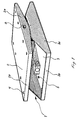
- Fig. 1
- is a perspective view of an embodiment of the device according to the invention,
- Fig. 2a
- is a perspective view of the upper plate dismounted from the lower plate,
- Fig. 2b
- is a perspective view of the lower plate with dismounted upper plate and dismounted drive means,
- Figs. 3a-c
- are end views of the device according to the invention, with parts of the upper and lower plates cut away in order to illustrate the positioning of the drive means, and illustrating alternative adjusted positions for the upper plate,
- Fig. 4
- is an end view of the apparatus according to the invention illustrating the alternative adjustment positions for the upper plate and a schematically indicated driver's seat mounted thereon, and
- Fig. 5
- is a bottom plane view of the upper plate, illustrating a modified embodiment with two drive means.
- As is clear especially from Figs. 1, 2a and 2b the
levelling device 1 according to the invention basically consists of anupper plate 2 and alower plate 3 which in the illustrated embodiment have a substantially square shape, as seen in a plane view, but which may naturally have any other suitable shape. Theupper plate 2 is provided with a number ofmounting holes 4 for mounting a driver's seat 11 (Fig. 4) thereon and thelower plate 3 is provided with a number ofmounting holes 5 for mounting the device directly on the vehicle or alternatively on a bracket or console. - The
upper plate 2 and thelower plate 3 are both provided with substantiallytriangular side walls side walls holes 6 and 7, respectively, for receiving abearing 8 for pivotal mounting of the plates relative to each other. The bearing is not illustrated in detail and may be of any suitable kind permitting a relatively frictionless pivoting of the plates in relation to each other. - In order to stabilize the pivotal connection between the plates the upper plate is preferably provided with a
support plate 9 which is fixed to, for instance welded to, the bottom side of theupper plate 2 adjacent and inwardly of one of theside walls 2a. This support plate is provided with a hole 9a corresponding to thehole 6 of theside wall 2a. In the same manner asupport plate 10 is welded to the bottom side of theupper plate 2 adjacent and inwardly of theopposite side wall 2a in order to support the other pivotal mounting. Likewise thissupport plate 10 is also provided with ahole 10a corresponding to thehole 6 in theother side wall 2a of the upper plate. - For strengthening the
upper plate 2 as well as thelower plate 3 these are preferably bent upwardly at the edges thereof not provided with side walls. These upwardly bent edges 2b and 3b, respectively, increase the torsional strength or stiffness of the plates and stabilize them. - For actuating the pivoting of the
upper plate 2 about thebearing 8 there is, according to the invention, employed a linearly working drive means 12 which is illustrated somewhat schematically in Figs. 2a, 3a-c and 5. In order to avoid load on the hydraulic system of the vehicle and in order not to run the risk of leakage of hydraulic fluid in the driver's compartment the device according to the invention preferably employs an electrical adjusting means such as SKF type CATR/L 12. The drive means 12 has a retractable andextendable operating rod 13 the outer free end of which is fixed in ablock 14 such as by means ofbolts 15 extended through theblock 14 and screwed into threaded bores in the end portion of theoperating rod 13. - On each side of the
operating rod 13 theblock 14 is provided witharms 16 which are firmly connected thereto and which at their opposite ends are pivotally mounted `in relation to theupper plate 2. Thearms 16 are pivotally mounted infurther support plates 17 which are welded to theupper plate 2 at a sufficient distance from each other to make sure that the drive means 12 can be received therebetween. In order not to obstruct the pivotal movement of the upper plate in relation to thelower plate 3 thesupport plates 17 slope down towards theplate 2, and one of the support plates is illustrated extended all the way down to the edge of the plate in order to further increase the stability. It is possible to give both support plates this shape. - The housing of the drive means 12 is provided with an
attachment 18, usually in the shape of a clevis, by means of which it is pivotally connected to asupport plate 19 welded to the upper side of thelower plate 3, whereby the pivotal connection is achieved in a well-known manner by means of apivoted mounting 20 which is not described in detail but which could for instance consist of a pin and a bushing. - In order to increase the stability and to lower the load on the drive means 12 this is, in the preferred embodiment, mounted at a position substantially centrally between the
side walls plates support plate 10, which in this case is given a greater height, so that one of thefurther support plates 17 can be eliminated. - For controlling the drive means 12, which is powered through the ordinary electrical system of the vehicle or possibly through a separate battery, there is provided a
control unit 21 which is only schematically indicated in Fig. 5. Thecontrol unit 21 is preferably an electronic control circuit composed of standard components and therefore not necessitating any detailed description thereof. The electronical circuit is provided in a protective casing which preferably also contains a not shown detecting means for detecting the position of theupper plate 2 and thus also for theseat 11 in relation to the horizontal. In this case, when the detecting means is also contained in the casing of thecontrol unit 21 this casing should naturally be mounted on the bottom side of theupper plate 2, as schematically illustrated in Fig. 5. The detecting means may be of any suitable kind, such as a mercury switch, an inertia sensitive pendulum or a photo-cell. - When the detecting device detects tilting of the
upper plate 2 in either direction in relation to the horizontal plane it delivers a corresponding signal to the control unit which is preferably provided with a time delay function of forinstance 1 to 3 seconds securing that the drive means is not activated by transitory tilts, so that the levelling device is not activated by smaller unevenness of the ground. - If the tilt of the vehicle remains after the time delay and the
control unit 21 activates the drive means 12 for extending thecontrol rod 13 this movement is transmitted to theupper plate 2 through thearms 16 and their connections with thesupport plates upper plate 2 is inclined or tilted from the position A in Figs. 3a and 4 and towards the position B (Figs. 3b and 4), whereby this movement continues until the detecting means detects that theupper plate 2 and thus the seat are in a horizontal position again. When thecontrol rod 13 of the drive means 12 is retracted this movement is likewise transmitted to theupper plate 2 through thearms 16 and thesupport plates 17 for swinging the upper plate awards the position C of Figs. 3c and 4. - In an embodiment where the distance between the upper and
lower plates upper plate 2 according to the invention may be tilted or pivoted approximately 13o to 15o in either direction in relation to thelower plate 3. However, the drive means 12 preferably comprises limit switches in connection with thecontrol rod 13, by means of which limit switches the stroke of the control rod and thereby the angles may be optionally adjusted. A typical value of the angle of adjustment has been found to be approximately 10o in either direction. - For reasons of appearance and most of all also for protecting the components a
rubber bellow 22, which is schematically illustrated in Fig. 4, is preferably fitted over the upper andlower plates - Although the device has so far been described with specific reference to an embodiment where the
upper plate 2 is only pivotal about an axis parallel with the lower plate it should also be realized that within the scope of the invention the device may also be modified in such away that the upper plate is adjustable about two axis which are positioned substantially perpendicularly in relation to each other. - By such a modification the
side walls bearings 8 attached thereto may be eliminated and thebearings 8 may be replaced by acentral support 23 which is schematically illustrated in Fig. 5 and which permits pivoting of theupper plate 2 about two axis which are parallel in relation to the lower plate. For pivoting the upper plate a second drive means 12', schematically illustrated in Fig. 5, is mounted such that its control rod 13' is extended perpendicularly to thecontrol rod 13 of the first drive means 12. In this case theupper plate 2 is naturally provided with corresponding additional support plates and arms and is the lower plate is provided with a corresponding additional support plate. Thecontrol unit 21 is also provided with a second detecting means for detecting the tilt of the upper plate about the additional axis. This modified embodiment does not bring about any increase in the vertical height of the device but possibly the dimensions of the upper and lower plates will have to be increased somewhat to make room for the two drive means. Moreover it may be necessary to give the support plates a specific shape in order to make room for the two drive means, but such modifications lie well within the competence of a man skilled in the art. - The invention should also in other respects be considered to encompass modifications and alterations obvious to a man skilled in the art, and the scope of the invention should therefore only be restricted by the enclosed patent claims.
Claims (8)
- Automatic levelling device for a vehicle seat (11), having at least one linearly working drive means (12, 12') operatively connected on the one hand to the vehicle seat, which is pivotal in relation to the vehicle about at least one axis (8; 23), and on the other hand to the vehicle, at least one detecting means for detecting the position of the seat in relation to the horizontal plane, said detecting means, when the seat (11) deviates from the horizontal plane, delivering a signal to the drive means (12, 12') for returning the seat to its horizontal position, and an upper plate (2) for supporting the seat (11), said upper plate being pivotally journalled (bearing 8; support 23) to a lower plate (3) to be mounted on the vehicle, the drive means (12, 12') being provided between the upper and lower plates (2, 3) completely within the space delimited by the plates, characterized in that the drive means (12, 12') extends substantially parallel to the lower plate (3), that is with a linearly working control rod (13) extendable and retractable respectively substantially parallel with the lower plate (3), and in that the free end of the control rod (13) is firmly connected to a block (14) provided with a pair of arms (16), which at one end are firmly attached to the block (14) and which at their other ends are pivotally mounted in support plates (10, 17) depending from the upper plate (2).
- Device according to claim 1, characterized in that the drive means (12, 12') consists (consist) of an electrical adjusting means.
- Device according to claims 1 or 2, characterized in that the housing of the drive means (12) is pivotally attached to a support plate (19) upright from the lower plate (3).
- Device according to any of the preceding claims, characterized in that the upper plate (2) may be tilted approximately 13° to 15°, preferably 10°, in relation to the lower plate (3) about the axis (bearing 8; support 23).
- Device according to claim 4, characterized in that the angle of adjustment may be set by controlling the stroke of the control rod (13) of the drive means (12) by means of limit switches provided in connection with the control rod (13).
- Device according to any of the preceding claims, characterized in that the distance between the upper plate (2) and the lower plate (3), when they are parallel, is approximately 10 to 11 centimeters.
- Device according to any of the preceding claims, characterized in that the device is provided with a control unit (21) receiving the signal from the detecting means and providing a time delay of between approximately 1 and 3 seconds, after receiving the signal from the detecting means, before the drive means (12, 12') is activated.
- Device according to any of the preceding claims, characterized by a rubber bellow (22) fitted over the upper plate (2) and the lower plate (3) for protecting the space therebetween.
Priority Applications (2)
| Application Number | Priority Date | Filing Date | Title |
|---|---|---|---|
| DE87902796T DE3786086T2 (en) | 1987-03-11 | 1987-03-11 | AUTOMATIC LEVEL CONTROL. |
| AT87902796T ATE90041T1 (en) | 1987-03-11 | 1987-03-11 | AUTOMATIC LEVEL CONTROL. |
Applications Claiming Priority (1)
| Application Number | Priority Date | Filing Date | Title |
|---|---|---|---|
| PCT/SE1987/000122 WO1988006984A1 (en) | 1987-03-11 | 1987-03-11 | Automatic levelling device |
Publications (2)
| Publication Number | Publication Date |
|---|---|
| EP0352256A1 EP0352256A1 (en) | 1990-01-31 |
| EP0352256B1 true EP0352256B1 (en) | 1993-06-02 |
Family
ID=20367163
Family Applications (1)
| Application Number | Title | Priority Date | Filing Date |
|---|---|---|---|
| EP87902796A Expired - Lifetime EP0352256B1 (en) | 1987-03-11 | 1987-03-11 | Automatic levelling device |
Country Status (12)
| Country | Link |
|---|---|
| US (1) | US5054739A (en) |
| EP (1) | EP0352256B1 (en) |
| JP (1) | JPH0764239B2 (en) |
| KR (1) | KR890700490A (en) |
| AT (1) | ATE90041T1 (en) |
| AU (2) | AU602139B2 (en) |
| BR (1) | BR8707975A (en) |
| CA (1) | CA1284764C (en) |
| DK (1) | DK172968B1 (en) |
| FI (1) | FI894076A (en) |
| NO (1) | NO169056C (en) |
| WO (1) | WO1988006984A1 (en) |
Families Citing this family (17)
| Publication number | Priority date | Publication date | Assignee | Title |
|---|---|---|---|---|
| US5588704A (en) * | 1992-08-13 | 1996-12-31 | Harza; Richard D. | Ergonomic antifatigue seating device and method |
| FR2735096B1 (en) * | 1995-06-09 | 1997-08-29 | Aerospatiale | ADJUSTABLE SAFETY SEAT FOR A VEHICLE SUCH AS AN AIRCRAFT. |
| AU688227B2 (en) * | 1996-02-05 | 1998-03-05 | Verward Pty. Ltd. | Seat for self-propelled narrow-track vehicle |
| AUPN786796A0 (en) * | 1996-02-05 | 1996-02-29 | Verward Pty Ltd (trading as Brooks Merchants) | Vehicle seat |
| US5884885A (en) * | 1996-07-18 | 1999-03-23 | Schmidt, Jr.; Anthony P. | Cradle assembly |
| SE9603786D0 (en) * | 1996-10-16 | 1996-10-16 | Klc Metallkonsult Ab | Self-leveling device for a seat |
| US6026920A (en) * | 1998-06-02 | 2000-02-22 | Edward G. Obeda | Dynamic seat-moving and leveling device |
| DE20101762U1 (en) * | 2001-02-01 | 2001-05-10 | Woerndl Matthias | Vehicle seat arrangement |
| US7490903B2 (en) * | 2006-05-23 | 2009-02-17 | Ruppe Fredy L | Tiltable seat mounting apparatus |
| US20080054150A1 (en) * | 2006-09-06 | 2008-03-06 | Stuby Lyle J | Seat tilting mechanism |
| US7707955B1 (en) | 2007-08-07 | 2010-05-04 | Sealift, Inc. | Transom platform lifting apparatus and method |
| US8950809B2 (en) | 2011-10-06 | 2015-02-10 | Thorley Industries Llc | Child restraint system with user interface |
| US10046677B2 (en) | 2013-04-23 | 2018-08-14 | Clearmotion Acquisition I Llc | Seat system for a vehicle |
| DK3434147T3 (en) * | 2017-07-28 | 2021-04-12 | Johannes Uhlenbrock | Chair |
| DE102018112004B4 (en) * | 2018-05-18 | 2021-08-05 | Grammer Aktiengesellschaft | Vehicle seat with a spring device |
| WO2021180764A1 (en) * | 2020-03-12 | 2021-09-16 | Medirent Ringgenberg | Chair |
| JP2023005484A (en) * | 2021-06-29 | 2023-01-18 | トヨタ自動車株式会社 | Chair |
Citations (1)
| Publication number | Priority date | Publication date | Assignee | Title |
|---|---|---|---|---|
| DE2141046A1 (en) * | 1971-08-17 | 1973-02-22 | Schulte Vieting Detlev Dipl In | REINFORCEMENT ELEMENT FOR PREFABRICATED THIN-SHELLED LARGE-AREA REINFORCED CONCRETE COMPOSITE PANELS |
Family Cites Families (22)
| Publication number | Priority date | Publication date | Assignee | Title |
|---|---|---|---|---|
| US2128273A (en) * | 1936-10-16 | 1938-08-30 | Bucyrus Erie Co | Leveling device |
| US2202009A (en) * | 1938-05-21 | 1940-05-28 | Bucyrus Erie Co | Leveling device |
| US2790119A (en) * | 1950-01-19 | 1957-04-23 | Bendix Aviat Corp | Servosystem stabilized platform |
| US2893134A (en) * | 1954-03-22 | 1959-07-07 | Preco Inc | Automatic leveling control and clinometer |
| US2872200A (en) * | 1955-08-16 | 1959-02-03 | Deere & Co | Leveling control for hillside machines |
| US2966937A (en) * | 1958-07-15 | 1961-01-03 | Rudolph C Rydberg | Self-levelling seat support |
| US3021107A (en) * | 1958-12-18 | 1962-02-13 | Kenneth C Salo | Self leveling tractor and implement seat |
| US3315934A (en) * | 1965-05-05 | 1967-04-25 | Taylor Ora Quinton | Self-leveling seat for tractors |
| US3269685A (en) * | 1965-05-28 | 1966-08-30 | Frank Hamachek Machine Company | Leveling control for electrically operating hydraulic leveling means |
| US3341165A (en) * | 1965-09-08 | 1967-09-12 | Taylor Ora Quinton | Automatic leveling seat for tractors and the like |
| DE1555946B2 (en) * | 1966-09-07 | 1978-04-13 | Kloeckner-Humboldt-Deutz Ag, 5000 Koeln | Work vehicle, especially tractor |
| US3741511A (en) * | 1971-06-01 | 1973-06-26 | G Streeter | Seat tilting structure |
| DE2142046A1 (en) * | 1971-08-21 | 1973-02-22 | Aristomenis Christodoulopoulos | CYBERNETIC SEAT CONTROL WHILE DRIVING |
| US3836162A (en) * | 1973-04-12 | 1974-09-17 | F Felkner | Self-levelling support for refrigerator or the like |
| DK484073A (en) * | 1973-09-03 | 1975-05-05 | L J Rasmussen | |
| DE2537174A1 (en) * | 1975-08-21 | 1977-03-03 | Rudolf Ing Grad Steigerwald | Lateral damping for vehicle seat - with pendant damped suspension on vertically sprung frame able to accommodate different driver weights |
| SE7603120L (en) * | 1976-03-09 | 1977-09-10 | Ostbergs Fabriks Ab | DEVICE IN FRONT OF THE TRAVELING WORK VEHICLE |
| NO140961C (en) * | 1976-08-03 | 1979-12-19 | Ivar Kalvatn | INSTALLATION OF CHAIR FOR USE IN BOATS OR VEHICLES |
| DE2637411A1 (en) * | 1976-08-19 | 1978-02-23 | Fritzmeier Kg Georg | SCISSOR SYSTEM FOR VEHICLE SEATS |
| US4095770A (en) * | 1976-11-01 | 1978-06-20 | Long Daniel C | Tiltable seat for tractor and the like |
| FR2450172A1 (en) * | 1979-03-02 | 1980-09-26 | Renard Jacques | Agricultural tractor seat support - has upper part double pivoted by perpendicular axes for adjustment and locked to lower at will |
| FR2472491A1 (en) * | 1979-12-26 | 1981-07-03 | Levy Pierre | Tractor seat inclination adjustment - has seat pivoted laterally with hydraulic cylinders setting angle and controlled by valve handle |
-
1987
- 1987-03-11 AT AT87902796T patent/ATE90041T1/en not_active IP Right Cessation
- 1987-03-11 AU AU72346/87A patent/AU602139B2/en not_active Ceased
- 1987-03-11 US US07/411,487 patent/US5054739A/en not_active Expired - Lifetime
- 1987-03-11 WO PCT/SE1987/000122 patent/WO1988006984A1/en active IP Right Grant
- 1987-03-11 BR BR8707975A patent/BR8707975A/en not_active IP Right Cessation
- 1987-03-11 JP JP62502261A patent/JPH0764239B2/en not_active Expired - Lifetime
- 1987-03-11 EP EP87902796A patent/EP0352256B1/en not_active Expired - Lifetime
- 1987-03-11 KR KR1019880701441A patent/KR890700490A/en not_active Application Discontinuation
-
1988
- 1988-02-18 CA CA000559257A patent/CA1284764C/en not_active Expired - Fee Related
- 1988-10-24 NO NO88884730A patent/NO169056C/en unknown
- 1988-11-08 DK DK198806220A patent/DK172968B1/en not_active IP Right Cessation
-
1989
- 1989-08-30 FI FI894076A patent/FI894076A/en not_active Application Discontinuation
-
1990
- 1990-11-28 AU AU67072/90A patent/AU623295B2/en not_active Ceased
Patent Citations (1)
| Publication number | Priority date | Publication date | Assignee | Title |
|---|---|---|---|---|
| DE2141046A1 (en) * | 1971-08-17 | 1973-02-22 | Schulte Vieting Detlev Dipl In | REINFORCEMENT ELEMENT FOR PREFABRICATED THIN-SHELLED LARGE-AREA REINFORCED CONCRETE COMPOSITE PANELS |
Also Published As
| Publication number | Publication date |
|---|---|
| AU623295B2 (en) | 1992-05-07 |
| KR890700490A (en) | 1989-04-25 |
| CA1284764C (en) | 1991-06-11 |
| NO169056B (en) | 1992-01-27 |
| JPH02502448A (en) | 1990-08-09 |
| DK622088D0 (en) | 1988-11-08 |
| WO1988006984A1 (en) | 1988-09-22 |
| EP0352256A1 (en) | 1990-01-31 |
| ATE90041T1 (en) | 1993-06-15 |
| AU6707290A (en) | 1991-02-14 |
| AU7234687A (en) | 1988-10-10 |
| JPH0764239B2 (en) | 1995-07-12 |
| FI894076A0 (en) | 1989-08-30 |
| BR8707975A (en) | 1990-04-17 |
| NO884730D0 (en) | 1988-10-24 |
| NO884730L (en) | 1988-10-24 |
| DK172968B1 (en) | 1999-10-25 |
| DK622088A (en) | 1988-11-08 |
| AU602139B2 (en) | 1990-10-04 |
| US5054739A (en) | 1991-10-08 |
| NO169056C (en) | 1992-05-06 |
| FI894076A (en) | 1989-08-30 |
Similar Documents
| Publication | Publication Date | Title |
|---|---|---|
| EP0352256B1 (en) | Automatic levelling device | |
| US5857535A (en) | Seat for self-propelled narrow-track vehicle | |
| US6206119B1 (en) | Electrical wheelchair with double frame structure | |
| US2284352A (en) | Seat | |
| CA2618759C (en) | Swivel seat and suspension apparatus | |
| US6640468B2 (en) | Vehicle mounted snowplow impact monitoring system and method | |
| ES2433125T3 (en) | Sensor device, adjustment device and work device | |
| EP0146791B1 (en) | A crane bracket for mounting over the chassis side members of a truck | |
| GB2213852A (en) | Bulldozer apparatus for a working vehicle | |
| US20040154844A1 (en) | Wheeled vehicle provided with an axle oscillating about a longitudinal axis | |
| AUPR560601A0 (en) | Self leveling tractor | |
| US4275800A (en) | Vehicle with variable height control station | |
| GB2325903A (en) | Kerb mounting wheeled conveyance | |
| JPH0144009Y2 (en) | ||
| JP3479417B2 (en) | Hitch support structure of work equipment | |
| JPS60179374A (en) | Anti-tilt device for tractor | |
| JPH0240730Y2 (en) | ||
| JPH0222Y2 (en) | ||
| JP2668526B2 (en) | Rice transplanter | |
| JPS5930650Y2 (en) | Agricultural tractor work equipment mounting device | |
| JPS61216606A (en) | Tilting control apparatus | |
| JPH027750Y2 (en) | ||
| KR0145536B1 (en) | Horizontal control device of a refrigerator | |
| US20070137070A1 (en) | Snow plow blade protection system | |
| JP3396794B2 (en) | Row coating machine |
Legal Events
| Date | Code | Title | Description |
|---|---|---|---|
| PUAI | Public reference made under article 153(3) epc to a published international application that has entered the european phase |
Free format text: ORIGINAL CODE: 0009012 |
|
| 17P | Request for examination filed |
Effective date: 19890823 |
|
| AK | Designated contracting states |
Kind code of ref document: A1 Designated state(s): AT BE CH DE FR GB IT LI LU NL SE |
|
| 17Q | First examination report despatched |
Effective date: 19920210 |
|
| GRAA | (expected) grant |
Free format text: ORIGINAL CODE: 0009210 |
|
| AK | Designated contracting states |
Kind code of ref document: B1 Designated state(s): AT BE CH DE FR GB IT LI LU NL SE |
|
| PG25 | Lapsed in a contracting state [announced via postgrant information from national office to epo] |
Ref country code: LI Effective date: 19930602 Ref country code: CH Effective date: 19930602 Ref country code: AT Effective date: 19930602 |
|
| REF | Corresponds to: |
Ref document number: 90041 Country of ref document: AT Date of ref document: 19930615 Kind code of ref document: T |
|
| REF | Corresponds to: |
Ref document number: 3786086 Country of ref document: DE Date of ref document: 19930708 |
|
| ITF | It: translation for a ep patent filed |
Owner name: DR. ING. A. RACHELI & C |
|
| REG | Reference to a national code |
Ref country code: CH Ref legal event code: PL |
|
| ET | Fr: translation filed | ||
| PG25 | Lapsed in a contracting state [announced via postgrant information from national office to epo] |
Ref country code: LU Free format text: LAPSE BECAUSE OF NON-PAYMENT OF DUE FEES Effective date: 19940331 |
|
| PLBE | No opposition filed within time limit |
Free format text: ORIGINAL CODE: 0009261 |
|
| STAA | Information on the status of an ep patent application or granted ep patent |
Free format text: STATUS: NO OPPOSITION FILED WITHIN TIME LIMIT |
|
| 26N | No opposition filed | ||
| EAL | Se: european patent in force in sweden |
Ref document number: 87902796.9 |
|
| PGFP | Annual fee paid to national office [announced via postgrant information from national office to epo] |
Ref country code: GB Payment date: 20000309 Year of fee payment: 14 |
|
| PGFP | Annual fee paid to national office [announced via postgrant information from national office to epo] |
Ref country code: DE Payment date: 20000329 Year of fee payment: 14 |
|
| PGFP | Annual fee paid to national office [announced via postgrant information from national office to epo] |
Ref country code: NL Payment date: 20000330 Year of fee payment: 14 Ref country code: FR Payment date: 20000330 Year of fee payment: 14 |
|
| PGFP | Annual fee paid to national office [announced via postgrant information from national office to epo] |
Ref country code: SE Payment date: 20000331 Year of fee payment: 14 |
|
| PGFP | Annual fee paid to national office [announced via postgrant information from national office to epo] |
Ref country code: BE Payment date: 20000413 Year of fee payment: 14 |
|
| PG25 | Lapsed in a contracting state [announced via postgrant information from national office to epo] |
Ref country code: GB Free format text: LAPSE BECAUSE OF NON-PAYMENT OF DUE FEES Effective date: 20010311 |
|
| PG25 | Lapsed in a contracting state [announced via postgrant information from national office to epo] |
Ref country code: SE Free format text: LAPSE BECAUSE OF NON-PAYMENT OF DUE FEES Effective date: 20010312 |
|
| PG25 | Lapsed in a contracting state [announced via postgrant information from national office to epo] |
Ref country code: BE Free format text: LAPSE BECAUSE OF NON-PAYMENT OF DUE FEES Effective date: 20010331 |
|
| BERE | Be: lapsed |
Owner name: WALLIN JAN Effective date: 20010331 |
|
| PG25 | Lapsed in a contracting state [announced via postgrant information from national office to epo] |
Ref country code: NL Free format text: LAPSE BECAUSE OF NON-PAYMENT OF DUE FEES Effective date: 20011001 |
|
| GBPC | Gb: european patent ceased through non-payment of renewal fee |
Effective date: 20010311 |
|
| EUG | Se: european patent has lapsed |
Ref document number: 87902796.9 |
|
| PG25 | Lapsed in a contracting state [announced via postgrant information from national office to epo] |
Ref country code: FR Free format text: LAPSE BECAUSE OF NON-PAYMENT OF DUE FEES Effective date: 20011130 |
|
| NLV4 | Nl: lapsed or anulled due to non-payment of the annual fee |
Effective date: 20011001 |
|
| REG | Reference to a national code |
Ref country code: FR Ref legal event code: ST |
|
| PG25 | Lapsed in a contracting state [announced via postgrant information from national office to epo] |
Ref country code: DE Free format text: LAPSE BECAUSE OF NON-PAYMENT OF DUE FEES Effective date: 20020101 |
|
| PG25 | Lapsed in a contracting state [announced via postgrant information from national office to epo] |
Ref country code: IT Free format text: LAPSE BECAUSE OF NON-PAYMENT OF DUE FEES Effective date: 20050311 |