US6640468B2 - Vehicle mounted snowplow impact monitoring system and method - Google Patents
Vehicle mounted snowplow impact monitoring system and method Download PDFInfo
- Publication number
- US6640468B2 US6640468B2 US10/084,129 US8412902A US6640468B2 US 6640468 B2 US6640468 B2 US 6640468B2 US 8412902 A US8412902 A US 8412902A US 6640468 B2 US6640468 B2 US 6640468B2
- Authority
- US
- United States
- Prior art keywords
- sensor
- switch
- frame
- vehicle
- snow plow
- Prior art date
- Legal status (The legal status is an assumption and is not a legal conclusion. Google has not performed a legal analysis and makes no representation as to the accuracy of the status listed.)
- Expired - Fee Related, expires
Links
Images


Classifications
-
- B—PERFORMING OPERATIONS; TRANSPORTING
- B60—VEHICLES IN GENERAL
- B60G—VEHICLE SUSPENSION ARRANGEMENTS
- B60G17/00—Resilient suspensions having means for adjusting the spring or vibration-damper characteristics, for regulating the distance between a supporting surface and a sprung part of vehicle or for locking suspension during use to meet varying vehicular or surface conditions, e.g. due to speed or load
- B60G17/015—Resilient suspensions having means for adjusting the spring or vibration-damper characteristics, for regulating the distance between a supporting surface and a sprung part of vehicle or for locking suspension during use to meet varying vehicular or surface conditions, e.g. due to speed or load the regulating means comprising electric or electronic elements
- B60G17/019—Resilient suspensions having means for adjusting the spring or vibration-damper characteristics, for regulating the distance between a supporting surface and a sprung part of vehicle or for locking suspension during use to meet varying vehicular or surface conditions, e.g. due to speed or load the regulating means comprising electric or electronic elements characterised by the type of sensor or the arrangement thereof
-
- E—FIXED CONSTRUCTIONS
- E01—CONSTRUCTION OF ROADS, RAILWAYS, OR BRIDGES
- E01H—STREET CLEANING; CLEANING OF PERMANENT WAYS; CLEANING BEACHES; DISPERSING OR PREVENTING FOG IN GENERAL CLEANING STREET OR RAILWAY FURNITURE OR TUNNEL WALLS
- E01H5/00—Removing snow or ice from roads or like surfaces; Grading or roughening snow or ice
- E01H5/04—Apparatus propelled by animal or engine power; Apparatus propelled by hand with driven dislodging or conveying levelling elements, conveying pneumatically for the dislodged material
- E01H5/06—Apparatus propelled by animal or engine power; Apparatus propelled by hand with driven dislodging or conveying levelling elements, conveying pneumatically for the dislodged material dislodging essentially by non-driven elements, e.g. scraper blades, snow-plough blades, scoop blades
-
- B—PERFORMING OPERATIONS; TRANSPORTING
- B60—VEHICLES IN GENERAL
- B60G—VEHICLE SUSPENSION ARRANGEMENTS
- B60G2300/00—Indexing codes relating to the type of vehicle
- B60G2300/09—Construction vehicles, e.g. graders, excavators
-
- B—PERFORMING OPERATIONS; TRANSPORTING
- B60—VEHICLES IN GENERAL
- B60G—VEHICLE SUSPENSION ARRANGEMENTS
- B60G2400/00—Indexing codes relating to detected, measured or calculated conditions or factors
- B60G2400/50—Pressure
-
- B—PERFORMING OPERATIONS; TRANSPORTING
- B60—VEHICLES IN GENERAL
- B60G—VEHICLE SUSPENSION ARRANGEMENTS
- B60G2400/00—Indexing codes relating to detected, measured or calculated conditions or factors
- B60G2400/60—Load
-
- B—PERFORMING OPERATIONS; TRANSPORTING
- B60—VEHICLES IN GENERAL
- B60G—VEHICLE SUSPENSION ARRANGEMENTS
- B60G2401/00—Indexing codes relating to the type of sensors based on the principle of their operation
- B60G2401/20—Switches, e.g. mercury or ball type switches
-
- B—PERFORMING OPERATIONS; TRANSPORTING
- B60—VEHICLES IN GENERAL
- B60G—VEHICLE SUSPENSION ARRANGEMENTS
- B60G2401/00—Indexing codes relating to the type of sensors based on the principle of their operation
- B60G2401/26—Resistance type, e.g. as level indicator
-
- B—PERFORMING OPERATIONS; TRANSPORTING
- B60—VEHICLES IN GENERAL
- B60G—VEHICLE SUSPENSION ARRANGEMENTS
- B60G2600/00—Indexing codes relating to particular elements, systems or processes used on suspension systems or suspension control systems
- B60G2600/04—Means for informing, instructing or displaying
- B60G2600/042—Monitoring means
-
- B—PERFORMING OPERATIONS; TRANSPORTING
- B60—VEHICLES IN GENERAL
- B60G—VEHICLE SUSPENSION ARRANGEMENTS
- B60G2600/00—Indexing codes relating to particular elements, systems or processes used on suspension systems or suspension control systems
- B60G2600/08—Failure or malfunction detecting means
-
- B—PERFORMING OPERATIONS; TRANSPORTING
- B60—VEHICLES IN GENERAL
- B60G—VEHICLE SUSPENSION ARRANGEMENTS
- B60G2800/00—Indexing codes relating to the type of movement or to the condition of the vehicle and to the end result to be achieved by the control action
- B60G2800/21—Traction, slip, skid or slide control
- B60G2800/214—Traction, slip, skid or slide control by varying the load distribution
-
- B—PERFORMING OPERATIONS; TRANSPORTING
- B60—VEHICLES IN GENERAL
- B60G—VEHICLE SUSPENSION ARRANGEMENTS
- B60G2800/00—Indexing codes relating to the type of movement or to the condition of the vehicle and to the end result to be achieved by the control action
- B60G2800/22—Braking, stopping
- B60G2800/222—Braking, stopping during collision
-
- B—PERFORMING OPERATIONS; TRANSPORTING
- B60—VEHICLES IN GENERAL
- B60G—VEHICLE SUSPENSION ARRANGEMENTS
- B60G2800/00—Indexing codes relating to the type of movement or to the condition of the vehicle and to the end result to be achieved by the control action
- B60G2800/90—System Controller type
- B60G2800/91—Suspension Control
- B60G2800/915—Suspension load distribution
-
- G—PHYSICS
- G05—CONTROLLING; REGULATING
- G05G—CONTROL DEVICES OR SYSTEMS INSOFAR AS CHARACTERISED BY MECHANICAL FEATURES ONLY
- G05G9/00—Manually-actuated control mechanisms provided with one single controlling member co-operating with two or more controlled members, e.g. selectively, simultaneously
- G05G9/02—Manually-actuated control mechanisms provided with one single controlling member co-operating with two or more controlled members, e.g. selectively, simultaneously the controlling member being movable in different independent ways, movement in each individual way actuating one controlled member only
- G05G9/04—Manually-actuated control mechanisms provided with one single controlling member co-operating with two or more controlled members, e.g. selectively, simultaneously the controlling member being movable in different independent ways, movement in each individual way actuating one controlled member only in which movement in two or more ways can occur simultaneously
- G05G9/047—Manually-actuated control mechanisms provided with one single controlling member co-operating with two or more controlled members, e.g. selectively, simultaneously the controlling member being movable in different independent ways, movement in each individual way actuating one controlled member only in which movement in two or more ways can occur simultaneously the controlling member being movable by hand about orthogonal axes, e.g. joysticks
- G05G9/04785—Manually-actuated control mechanisms provided with one single controlling member co-operating with two or more controlled members, e.g. selectively, simultaneously the controlling member being movable in different independent ways, movement in each individual way actuating one controlled member only in which movement in two or more ways can occur simultaneously the controlling member being movable by hand about orthogonal axes, e.g. joysticks the controlling member being the operating part of a switch arrangement
- G05G9/04788—Manually-actuated control mechanisms provided with one single controlling member co-operating with two or more controlled members, e.g. selectively, simultaneously the controlling member being movable in different independent ways, movement in each individual way actuating one controlled member only in which movement in two or more ways can occur simultaneously the controlling member being movable by hand about orthogonal axes, e.g. joysticks the controlling member being the operating part of a switch arrangement comprising additional control elements
Definitions
- Typical snowplow systems designed to be mounted on smaller vehicles operate by providing a plow blade pivotally mounted on a support arm which, in turn, is pivotally mounted to the vehicle frame.
- a first mechanism is used to raise or lower the plow by causing the support arm to pivot around an axis proximate the vehicle.
- This first mechanism is usually a hydraulic piston assembly or, in simpler cases, an electric winch. While plowing, the plow is in a lowered position and can pivot around a horizontal axis defined by a hinge which connects the plow to the distal end of the support arm.
- a spring or similar biasing mechanism extends from an attachment point on the support arm to another attachment point on the top of the plow.
- the spring controls the rotation of the plow around its axis of rotation by biasing the lower, leading edge of the plow in a forward direction.
- the plow In the event that the plow contacts a relatively immovable object, the plow is allowed to rotate around its hinge such that the leading edge rotates rearwardly, thereby stretching the spring. Once the object has passed under the leading edge, the spring pulls the top edge of the plow back, thereby rotating the leading edge forward to its normal operating position. This damping feature protects the vehicle frame from encountering excessive forces during a plowing operation.
- Rudimentary systems rely on the weight and shape of the plow to provide the downward force necessary to keep the plow close to the ground during operation. More advanced systems have additional measures for providing downward force. Such force is desirable when using a plow to scrape hard-packed snow and ice from a road's surface. Providing such a downward force must be done in a controlled manner to prevent injury to the plow and vehicle.
- Existing systems utilize hydraulic pressure sensors in order to maintain a predetermined downward pressure on the blade of the plow. Unfortunately, there are many problems pertaining to the complexity of these systems.
- the existing hydraulic systems necessarily include a significant number of electrical wires extending from the sensors to the plow control system. These wires are susceptible to breaking and corrosion. As snowplows are used in cold environments and typically come into contact with corrosive salts, minimizing the number of electrical wires exposed to these harsh conditions would be beneficial.
- the various embodiments of the present invention pertain generally to a plow system which includes a control system that monitors the downward pressure exerted by the blade as a function of the spatial relationship between the vehicle frame and the ground. As the downward pressure of the blade increases, the front of the vehicle is lifted somewhat, relieving some of the weight the vehicle places on its front suspension, thereby increasing the distance between the vehicle frame and the ground or an object substantially fixed relative to the ground, such as the front axle or wheel.
- the relative simplicity of this system allows it to be added to the front or the rear frames of existing sport utility vehicles or light trucks. Additionally, by constantly monitoring the performance and position of the vehicle's front suspension, the system lends itself to the inclusion of limit or overload measures to ensure the suspension will not be damaged during operation of the plow.
- One embodiment of the present invention includes a telescoping sensor linkage attached to the frame of the carrier vehicle with an upper bracket.
- the linkage is directed downwardly and abuts against a lower bracket which is fixed relative to the vehicle's front axle.
- the telescoping sensor linkage is constructed and arranged to sense and measure changes in the distance between the upper bracket and the lower bracket and sends this information, either mechanically or electronically, to a plurality of micro switches.
- the micro switches are operably attached to valve controllers which control the flow of hydraulic fluid through the hydraulic cylinders.
- One of these micro switches then, can be designated as a pressure increase switch while the other can be designated as a pressure decrease switch. Alternatively, more than two micro switches may be used.
- micro switches it may be desirable to use four micro switches to provide redundancy in the event that one or both of the other micro switches malfunctions. It may also be desire to designate two of the micro switches for use in a relatively light plowing operation such as light snow, and designate the other two micro switches for use during heavier operation such as plowing heavy snow and ice, spreading gravel, or grading operations.
- the distance between the upper and lower brackets of this embodiment is representative of a load placed on the suspended frame of the vehicle. It is understood that the device could be constructed and arranged to measure the distance between the suspended frame and the ground, however, the inclusion of a lower bracket provides a relatively clean surface against which the telescoping sensor can act. Such a mechanical sensor measuring distance to the ground by actually coming in contact therewith, would likely encounter obstacles such as snow and ice during operation, and would render such a configuration impractical.
- Another embodiment of the present invention includes an electronic proximity sensor, similarly mounted to the vehicle frame, and directed toward a lower mounting bracket which provides a flat, horizontal target against which the proximity sensor may measure distance.
- the proximity sensor could be directed at the ground and measure distance therefrom, the bracket provides a surface which is free from irregularities and, therefore, would provide a more accurate indication of the front-end loading the vehicle is experiencing due to the downward pressure of the plow.
- the electronic proximity sensor is electrically connected to an electronic control box which accepts data from the proximity sensor and uses it to control the flow of hydraulic fluid in the cylinder used to control the vertical position of the plow blade.
- the electronic control box also provides data to the vehicle operator who can then adjust the downward pressure of the blade and the mode of operation thereof, from the cab of the carrier vehicle.
- Another embodiment uses a variable resistor to convert the mechanical reading of changes in the elevation of the frame to an electrical representation.
- a mechanical linkage such as that described above, is operably connected with a potentiometer or variable resistor so that when the frame moves up and down, the current flowing out of the variable resistor changes, thereby providing a current to a control system having fluctuations representative of the changes in elevation of the frame.
- the various embodiments of the present invention provide multiple modes of operation of the plow blade.
- One such mode of operation is a “float” mode. While operating in the float mode, the valves porting fluid to either side of the hydraulic cylinder are left open, allowing it to move freely, so that the weight of the plow may be used to provide the necessary down pressure. As the plow blade encounters contours in the road surface, the hydraulic fluid is allowed to flow between other sides of the hydraulic cylinder, thereby allowing the plow blade to raise or lower as necessary and “float” over the surface of the road.
- the proximity sensor may be used as an overload protection device. If an extreme contour is encountered, the sensor would detect an abrupt change in the load on the vehicle's suspension, activate the hydraulic pump, and close the ports to the cylinder as necessary to raise or lower the plow blade.
- Another such mode of operation is the “down pressure” mode.
- the vehicle operator selects a desired amount of pressure that he or she wants the blade to be putting on the surface being plowed. This amount of pressure will correspond to a distance between the suspended vehicle frame and elevation which is relatively fixed to the ground such as that of a wheel or an axle. That distance is then monitored and corrections are made to the elevation of the snowplow such that the set distance or load on the vehicle's suspension is maintained during operation.
- Manual mode may be desired when various levels of ice buildup exist on a relatively flat surface and it is desired to use the plow blade to scrape the ice off of the surface, regardless of load.
- Another application of manual mode may be when it is desired to leave a gap between the bottom of the plow and the hard ground such as may be the case when using the plow to spread a layer of gravel or other granular material.
- a switch is provided for this mode of operation which allows the operator to raise and lower the blade to a certain elevation and sufficiently fix the height of the blade, relative to the vehicle, during operation.
- a plurality of operator control configurations are envisioned and described in more detail herein.
- FIG. 1 is a schematic drawing of an embodiment of a snow plow system of the present invention
- FIG. 2 is a schematic drawing of an alternative embodiment of a snow plow system of the present invention.
- FIG. 3 is a schematic drawing of another alternative embodiment of a snow plow system of the present invention.
- FIGS. 4A-E are diagrammatic views of a preferred embodiment of the control system of the present invention shown in various positions;
- FIG. 4F is a diagrammatic view of an alternative embodiment of the control system of the present invention.
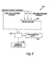
- FIG. 5 is a diagrammatic view of another alternative embodiment of the control system of the present invention.
- FIGS. 6A-D are diagrammatic side views of a control switch of the present invention in various positions corresponding to different modes of operation;
- FIG. 7 is a side elevation of a joystick controller of the present invention.
- FIG. 8 perspective view of an alternative embodiment of a handheld controller of the present invention.
- FIG. 9 is a perspective view of a control box of the present invention.
- FIG. 10 is a perspective view of an alternative joystick controller of the present invention.
- Snow plow system 100 which is attachable to an existing light truck such as a pickup truck or sport utility vehicle.
- Snow plow system 100 generally comprises a mounting bracket 180 , mountable to a vehicle frame 160 .
- the vehicle frame 160 is attached to an axle 210 , preferably through a suspension mechanism such as a vehicle spring 200 .
- the snow plow system 100 includes a support arm 110 which is attached to plow blade 120 at its forward end.
- the plow blade 120 is pivotally attached to support arm 110 and can pivot forwardly and rearwardly around a horizontal axis.
- a spring (not shown) may be provided to pull the top portion of the plow blade 120 rearward toward support arm 110 , thereby biasing the bottom edge of plow blade 120 forward.
- Support arm 110 is pivotally attached at its rearward end to the mounting bracket 180 , such that support arm 110 may be raised and lowered around a horizontal axis by positioner 130 .
- Positioner 130 is attached at one end to vehicle frame 160 and at the other end to support arm 110 .
- positioner 130 includes at least one hydraulic cylinder 132 .
- the hydraulic cylinder 132 houses a piston that may slide within the cylinder 132 and is connected to a push rod 134 which makes up the end of the cylinder 132 attached to support arm 110 .
- An oil distribution box houses valves used to port hydraulic oil to and from either side of the piston, thereby causing the piston to slide back and forth within the cylinder 132 , raising and lowering support arm 110 .
- Pressurized hydraulic fluid is supplied by a hydraulic oil pump (not shown).
- the snow plow system 100 measures the impact mounting bracket 180 has on vehicle frame 160 during operation and particularly whether the impact increases above or drops below a predetermined set load. This measurement is taken using sensor 140 that is attached to vehicle frame 160 .
- the sensor 140 measures fluctuations in the load felt by vehicle frame 160 by detecting variations in the distance between the vehicle frame 160 and a reference point.
- the reference point is a point fixed relative to at least one of the wheels such as bracket 220 attached to vehicle axle 210 , shown in FIG. 1, or the ground 240 , shown in FIG. 2 .
- Sensor 140 interprets these fluctuations as indicative of the impact felt by vehicle frame 160 from the mounting bracket 180 and sends corresponding data, mechanical or electrical, to control system 150 .
- the control system 150 uses the data to determine whether the load has changed from the predetermined set load, and what reaction is appropriate, as described below.
- Sensor 140 may be a proximity sensor, such as an electronic proximity sensor shown in FIGS. 1 and 2. Examples of acceptable electronic proximity sensors include ultrasonic, laser, infrared, SONAR, and RADAR. Alternatively, the sensor 140 may be a mechanical sensor as shown in FIG. 3 . In this embodiment, sensor 140 is attached to vehicle frame 160 and includes a telescoping linkage 142 that contacts a target surface that serves as a reference point, substantially fixed relative to at least one of the wheels such as a bracket 220 . By monitoring the telescoping linkage 142 as it expands and contracts, the mechanical sensor 140 detects variations in the distance between vehicle frame 160 and axle 210 .
- a telescoping linkage 142 that contacts a target surface that serves as a reference point, substantially fixed relative to at least one of the wheels such as a bracket 220 .
- Control system 150 receives load data from the sensor 140 and controls the positioner 130 used to pivot support arm 110 accordingly to maintain a target load selected by the vehicle operator.
- control system 150 is a closed-loop feedback system.
- the control system preferably includes a manual mode whereby control system 150 controls the positioner 130 in response to manual instruction provided from a user.
- control system 150 Upon receipt of load change data received from sensor 140 , control system 150 sends instructions to the positioner 130 , and upon receipt of these instructions, the positioner 130 causes the support arm 110 pivot accordingly.
- positioner 130 includes the hydraulic cylinder 132 , controlled by porting oil to either side of a piston (not shown) slideably housed therein.
- the piston is connected to the push rod 134 , shown in FIGS. 1-3, which in turn is attached to support arm 110 , and therefore, by so controlling the oil distribution, control system 150 thereby directs positioner 130 to pivot support arm 110 and completes the feedback system.
- control system 150 is electromechanical and provides feedback utilizing at least one switch 300 having at least two positions.
- the switch 300 changes positions in response to changes in the predetermined set load as described below.
- Data is conveyed from sensor 140 to control system 150 by movement of a sliding shaft 260 mechanically connected to sensor 140 . This movement is proportional to the fluctuations of the load felt by vehicle frame 160 .
- Sliding shaft 260 is mechanically connected to sensor 140 and is arranged to activate and deactivate micro switches 300 as the actual load increases or decreases relative to the predetermined set load as described below.
- control system 150 sends instructions to positioner 130 to pivot support arm 110 .
- These instructions take the form of electronic signals from micro switches 300 .
- micro switches 300 there are two micro switches 300 , one designated as a pressure increase switch 300 A and the other designated as a pressure decrease switch 300 B, shown in FIG. 4 A.
- These switches 300 are fixedly attached to bracket 316 , which holds the control system 150 to the vehicle frame 160 .
- Sliding shaft 260 is slideably attached to bracket 316 such that it can move relative to bracket 316 as shown in FIG. 4 A.
- Sliding shaft 260 has a cap 314 attached to one end to restrict the sliding movement from over-extension.
- Actuators 310 are fixedly attached to sliding shaft 260 by set screws 312 , which allow the locations of the actuators 310 to be adjusted, if necessary. Each micro switch 300 can come into contact with an actuator 310 , thereby activating the micro switch 300 .
- sliding shaft 260 will rest in its neutral position, shown in FIG. 4A, such that neither micro switch 300 touches an actuator and both micro switches 300 are therefore deactivated.
- sliding shaft 260 responds by moving to the left into the overload position, shown in FIG. 4B, such that micro switch 300 B contacts the actuator 310 B and the pressure decrease switch 300 B is activated.
- the activation of the pressure decrease switch 300 B causes the oil to be ported through the hydraulic cylinder 132 such that the pressure therein is relieved, causing the actuator 310 B to move to the right until the sliding shaft 260 achieves the neutral position once again.
- sliding shaft 260 responds by moving to the right into the underload position, shown in FIG. 4C, such that the micro switch 300 A contacts the actuator 310 A and the pressure increase switch 300 A is activated until the sliding shaft 260 moves to the left and the neutral position is again achieved.
- control system 150 may implement the two micro switches 300 for deriving additional information about the pressure on vehicle frame 160 , such as underloads that exceed a preset limit, shown in FIGS. 4D and 4E.
- FIG. 4D shows the circumstance where the load decreases past a set limit such that both micro switches 300 A and 300 B contact actuator 310 A.
- both switches 300 are activated, all oil ports are opened, thereby releasing all pressure; to prevent damaging the hydraulic system, mounting bracket 180 , and/or vehicle frame 160 .
- FIG. 4E shows the circumstance where the load decreases past yet a further limit such that micro switch 300 B contacts actuator 310 A but micro switch 300 A no longer contacts any actuator 310 .
- a microprocessor 605 is preferably operably connected to the switches 300 and is constructed and arranged for accepting input therefrom and keeping historical data pertaining to the positions of the switches 300 .
- the microprocessor registers a condition whereby switch 300 A is “off” and switch 300 B is “on”.
- the microprocessor also notes that this condition occurred immediately after an “on—on” condition, as was shown in FIG. 4 D.
- the microprocessor is thus able to distinguish the condition shown in FIG. 4E from the condition shown in FIG. 4B, and act accordingly, preferably by canceling all functions and releasing all pressures, in order to prevent equipment damage.
- control system 150 may implement three or four micro switches 300 , shown in FIG. 4F, thereby providing redundancy in the control system in the event that a micro switch 300 malfunctions.
- the redundancy is provided by designating two micro switches 300 as pressure increase switches—micro switches 300 A and 300 C—and designating the other two switches as pressure decrease switches—micro switches 300 B and 300 D. All of the switches 300 are shown diagrammatically as being operably connected to the microprocessor 605 . However, additional redundancy may be achieved by providing multiple microprocessors.
- micro switches 300 shown in FIG. 4F alternatively allows the control system 150 to operate micro switches 300 in varying modes, designating two micro switches 300 for use in relatively light plowing conditions—micro switch 300 A as a pressure increase switch and micro switch 300 B as a pressure decrease switch—and designating the other two micro switches 300 for use in relatively heavy plowing conditions—micro switch 300 C as a pressure increase switch and micro switch 300 D as a pressure decrease switch.
- These conditional designations may be achieved, for instance, by locating switches 300 C and 300 D in closer proximity to each other. This way, switches 300 A and 300 B are acted upon first by movement of the actuators 310 , signifying normal or light movement. 300 C and 300 D would become actuated only when more significant or heavy movement of the actuators 310 occurs.
- control system 150 may even implement only a single micro switch 300 for receiving data from sensor 140 .
- FIGS. 4A through 4F depict mechanical embodiments of the control system 150 .
- the control system 150 may make the transition from mechanical to electronic by using a device such as a variable resistor 600 .
- the variable resistor 600 is constructed and arranged such that the amount of resistive material current passing through the resistor encounters is proportionate to the distance measured by the sensor 140 .
- the current flowing through variable resistor 600 changes, thereby providing a current to the microprocessor 605 , preferably via an analog to digital converter (not shown) that has fluctuations representative of the changes in the load felt by vehicle frame 160 .
- the present invention may operate in multiple modes, and the control system 150 operates uniquely in each.
- One such mode of operation is a “down pressure” mode, or feedback mode as described above.
- this mode there is a predetermined set load that indicates the desired amount of pressure on the vehicle frame 160 and may be selected by the vehicle operator.
- control system 150 makes corrections to the elevation of the plow blade 120 such that the predetermined set load on the vehicle frame 160 is maintained during operation.
- Another mode of operation is the “float” mode.
- This mode allows snow plow blade 120 to “float” over the surface being plowed.
- the valves in the oil distribution box (not shown) which port fluid to either side of the hydraulic cylinder 132 are left open, thereby allowing the cylinder to move freely, so that the weight of plow blade 120 alone may be used to provide downward pressure.
- the hydraulic fluid is allowed to flow between opposite sides of the hydraulic cylinder 132 , thereby allowing the plow blade 120 to raise or lower as necessary.
- control system 150 may function to protect from an overload, but will not react to minor fluctuations in the load felt by vehicle frame 160 . If plow blade 120 encounters an extreme contour, sensor 140 detects an abrupt change in the load on vehicle frame 160 , and control system 150 activates the hydraulic pump and closes the ports to the cylinder 132 as necessary to raise or lower plow blade 120 and counteract the extreme contour.
- manual mode is desirable when multiple levels of ice have built up and exist on a relatively flat surface.
- manual operation mode allows the plow blade 120 to scrape the ice off the surface, regardless of load.
- the vehicle operator directs control system 150 to raise plow blade 120 and then stop at the desired height.
- the manual mode further allows the snow plow system 100 to maintain a gap between the bottom of plow blade 120 and ground 240 , which facilitates functions in addition to plowing snow such as spreading a layer of gravel or other granular material.
- control system 150 preferably includes a controller 610 , shown diagrammatically in FIG. 5, and depicted in various embodiments in FIGS. 7-10.
- the controller 610 may be fixedly positioned within the vehicle cab such that it is operable by the vehicle operator.
- the controller 610 may be embodied as a handheld remote, either tethered or wireless, useable within the vehicle cabin.
- Each of the various controller embodiments includes a switch 705 used to toggle the snow plow system 100 between the different modes of operation.
- a preferred embodiment of this switch 705 is shown in FIGS. 6A-6D, in each of the various positions of the switch 705 .
- the switch 705 could be wired in a variety of ways, a preferred embodiment has the up position, shown in FIG. 6A, corresponding to a “plow up” mode, whereby the plow 120 is held up when not in use.
- This switch position is preferably spring-loaded such that, when released, the switch returns to an “off” position.
- the next position, shown in FIG. 6B, is the off position. The off position holds the plow 120 in its present position.
- the switch 705 is moved to the plow up position of FIG. 6A until a desired height is achieved and then released.
- the switch 705 then automatically returns to the off position of FIG. 6 B and holds the plow 120 at the desired height.
- the next position, shown in FIG. 6C, corresponds to the float mode.
- the switch 705 is constructed and arranged to remain in this position when selected.
- the float mode energizes the control system 150 such that the feedback system is in operation.
- the final position, shown in FIG. 6D is a momentary “down” position similar to that of the up position shown in FIG. 6 A. The down position increases the downward pressure placed on the plow by adjusting the feedback loop accordingly.
- the microprocessor 605 is given a different target pressure.
- the switch 705 When the switch 705 is released, it returns to the float mode position of FIG. 6 C. However, the plow 120 is now “floating” with an exerted downward pressure. Thus, the plow system 100 is in a down-pressure mode.
- control system 150 Placing the control system 150 in float mode allows oil to flow freely to either side of the cylinder 132 . This creates a situation whereby the plow 120 follows contours in the plowing surface. The downward pressure exerted by the plow is a result of the weight of the plow 120 .
- the control system 150 uses data from the sensor 140 to ensure that any absolute limits set are not exceeded.
- FIGS. 7-10 show various embodiments of the controller 610 .
- FIG. 7 shows a preferred embodiment whereby the controller 610 comprises a handheld joystick 700 , operable within the cabin of the vehicle.
- the joystick 700 includes the mode switch 705 ergonomically positioned thereon.
- An LED 710 is operably placed on top of the joystick 700 and is preferably capable of emitting at least two colors, such as red and green, such that different meanings may be associated with each color.
- the LED 710 may be operably connected to the microprocessor 605 such that the microprocessor may cause the LED to emit a green light when the control system 150 is operating in the float mode, and a red light when the control system 150 is operating in the down pressure mode.
- FIG. 8 shows a controller 610 in the form of a handheld remote 720 , in tethered communication with the microprocessor 605 with a cord 725 .
- remote 720 includes the mode switch 705 and at least one LED indicator 710 . Additional buttons and indicators may also be provided such as plow angle control buttons 730 , plow light control/indicator 735 and power button/indicator 740 .
- FIG. 9 shows yet another preferred embodiment of controller 610 in the form of a control box 750 .
- the control box 750 is an advantageous embodiment of controller 610 in that it may be mounted overhead, and is relatively inexpensive to manufacture.
- the control box 750 is preferably pivotally mounted on a bracket 755 and communicates with the microprocessor 605 using a cord 760 .
- the control box 750 may include the same controls and indicators, 705 , 710 , 730 , 735 , and 740 as handheld remote 720 .
- FIG. 10 shows still another preferred embodiment of controller 610 in the form of a joystick controller 765 .
- switch 705 is embodied as a stick 770 moveably attached to a base 775 .
- the stick 770 is constructed and arranged so that it may be moved in one direction to instruct the microprocessor 605 to place the system 150 in “plow up” mode. Releasing the stick 770 places the system 150 in off mode, whereby the previous setting is maintained, as described above. Moving the stick 770 in an opposite direction, until a green LED indicator 710 is illuminated, places the system 150 in the float mode. Holding the stick 770 in this position for a predetermined time, indicated by the LED 710 shining a red light, places the system 150 in a down pressure mode.
- the stick 770 may be moved side to side as well in order to control the angle of the plow blade 120 . Switches 735 and 740 for lights and power, respectively, may be placed on the base 775 .
Landscapes
- Engineering & Computer Science (AREA)
- Mechanical Engineering (AREA)
- Architecture (AREA)
- Civil Engineering (AREA)
- Structural Engineering (AREA)
- Lifting Devices For Agricultural Implements (AREA)
Abstract
Description
Claims (53)
Priority Applications (2)
| Application Number | Priority Date | Filing Date | Title |
|---|---|---|---|
| US10/084,129 US6640468B2 (en) | 2001-02-27 | 2002-02-25 | Vehicle mounted snowplow impact monitoring system and method |
| CA002373781A CA2373781A1 (en) | 2001-02-27 | 2002-02-27 | Vehicle mounted snowplow impact monitoring system and method |
Applications Claiming Priority (2)
| Application Number | Priority Date | Filing Date | Title |
|---|---|---|---|
| US27180201P | 2001-02-27 | 2001-02-27 | |
| US10/084,129 US6640468B2 (en) | 2001-02-27 | 2002-02-25 | Vehicle mounted snowplow impact monitoring system and method |
Publications (2)
| Publication Number | Publication Date |
|---|---|
| US20020133981A1 US20020133981A1 (en) | 2002-09-26 |
| US6640468B2 true US6640468B2 (en) | 2003-11-04 |
Family
ID=26770630
Family Applications (1)
| Application Number | Title | Priority Date | Filing Date |
|---|---|---|---|
| US10/084,129 Expired - Fee Related US6640468B2 (en) | 2001-02-27 | 2002-02-25 | Vehicle mounted snowplow impact monitoring system and method |
Country Status (2)
| Country | Link |
|---|---|
| US (1) | US6640468B2 (en) |
| CA (1) | CA2373781A1 (en) |
Cited By (23)
| Publication number | Priority date | Publication date | Assignee | Title |
|---|---|---|---|---|
| US6701857B1 (en) * | 2003-01-16 | 2004-03-09 | Lynn David Jensen | Depth control device for planting implement |
| US20060021819A1 (en) * | 2004-07-30 | 2006-02-02 | Caterpillar Inc. | Work machine tool control console |
| US20060171163A1 (en) * | 2005-01-31 | 2006-08-03 | Sno-Way International, Inc. | Independent lighting system and method |
| US20060172559A1 (en) * | 2005-01-31 | 2006-08-03 | Menze William F | Independent lighting energy interruption system with advanced reconfiguration and method |
| US20070128013A1 (en) * | 2005-12-01 | 2007-06-07 | Grant Hanson | Apparatus protecting vehicle with bucket when bucket strikes fixed object |
| US20070214683A1 (en) * | 2006-03-03 | 2007-09-20 | Almadani Mazen W | Lost motion mechanism for movable vehicle implements |
| US20070277405A1 (en) * | 2006-06-01 | 2007-12-06 | Deere & Company | Control system for an electronic float feature for a loader |
| US20080178497A1 (en) * | 2007-01-29 | 2008-07-31 | Dimauro Anthony R | System and method for expeditious snowplow mounting |
| US20080201994A1 (en) * | 2007-01-17 | 2008-08-28 | Muncie Power Products, Inc. | Electrohydraulic control system for a vehicle |
| US20080230364A1 (en) * | 2006-05-15 | 2008-09-25 | Paul Treuthardt | Joystick control device |
| US20090040780A1 (en) * | 2005-01-31 | 2009-02-12 | Menze William F | Independent Lighting Energy Interruption System With Energy Subdivisioning And Method |
| US8732988B2 (en) | 2006-11-30 | 2014-05-27 | Glenridge, Inc. | Implement with linkage assembly and work assembly wherein work assembly has dynamic skid shoe and a scraping edge |
| US8793907B2 (en) | 2012-06-01 | 2014-08-05 | Northern Star Industries, Inc. | Snowplow blade articulator assembly with passive downforce mechanism |
| US8840353B2 (en) | 2011-09-20 | 2014-09-23 | Walter M. Hopkins | Vehicle mounted highway refuse collector |
| US8881433B2 (en) | 2006-11-30 | 2014-11-11 | Glenridge, Inc. | Implement attaching to a forward motion-producing machine for elevating an edge encountering an immovable object |
| DE102015222847A1 (en) * | 2015-11-19 | 2017-05-24 | Robert Bosch Gmbh | Method for protecting a unit for clearing snow on a vehicle |
| US9826677B2 (en) | 2014-12-16 | 2017-11-28 | Cnh Industrial Canada, Ltd. | Seed implement incorporating a down pressure sensing and adjustment system |
| US9885159B1 (en) | 2016-01-13 | 2018-02-06 | Michael Lee Curtis | Vehicle debris clearing device |
| US10066361B2 (en) | 2016-04-07 | 2018-09-04 | 906 Engineering Corp. | Plow lift and down pressure control mechanisms, systems, and methods |
| US11427979B1 (en) * | 2020-01-19 | 2022-08-30 | Chris Lee Nelson | Plow collateral damage mitigating system |
| US20230257952A1 (en) * | 2022-02-16 | 2023-08-17 | Paladin Grands Group, Inc. | Movable back drag blade for snow blower |
| US11820197B2 (en) | 2022-02-09 | 2023-11-21 | Honda Motor Co., Ltd. | Vehicle control arm assembly |
| US12148300B1 (en) | 2020-01-19 | 2024-11-19 | Chris Lee Nelson | Plow collateral damage mitigating system |
Families Citing this family (5)
| Publication number | Priority date | Publication date | Assignee | Title |
|---|---|---|---|---|
| CA2519960A1 (en) * | 2004-09-15 | 2006-03-15 | Ludington Technologies, Inc. | Universal control adapter system |
| JP7164294B2 (en) * | 2017-10-24 | 2022-11-01 | 株式会社小松製作所 | work vehicle |
| ES2947616T3 (en) | 2019-11-19 | 2023-08-14 | Bucher Municipal Ag | Automotive sweeper for cleaning walkable and/or walkable floor surfaces |
| CN111664826B (en) * | 2020-06-28 | 2024-09-27 | 三一汽车制造有限公司 | Distance detection device and work vehicle |
| CN112549891A (en) * | 2020-11-23 | 2021-03-26 | 上海威曼汽车零部件有限公司 | Light trailer air suspension system |
Citations (4)
| Publication number | Priority date | Publication date | Assignee | Title |
|---|---|---|---|---|
| US5265356A (en) * | 1992-10-14 | 1993-11-30 | Winter Kent L | Snowplow and hydraulic system for same |
| US5829174A (en) | 1994-04-08 | 1998-11-03 | Sno-Way International, Inc. | Articulated snowplow system |
| US5832637A (en) | 1993-04-26 | 1998-11-10 | Aguado; Aleck P. | Method of operating a snowplow |
| US5901476A (en) * | 1997-06-26 | 1999-05-11 | Buonfiglio; Nick J. | Plow lift system |
-
2002
- 2002-02-25 US US10/084,129 patent/US6640468B2/en not_active Expired - Fee Related
- 2002-02-27 CA CA002373781A patent/CA2373781A1/en not_active Abandoned
Patent Citations (7)
| Publication number | Priority date | Publication date | Assignee | Title |
|---|---|---|---|---|
| US5265356A (en) * | 1992-10-14 | 1993-11-30 | Winter Kent L | Snowplow and hydraulic system for same |
| US5832637A (en) | 1993-04-26 | 1998-11-10 | Aguado; Aleck P. | Method of operating a snowplow |
| US5987785A (en) | 1993-04-26 | 1999-11-23 | Sno-Way International, Inc. | Reactive controlled mechanism for a snow-plow |
| US6044579A (en) | 1993-04-26 | 2000-04-04 | Sno-Way International, Inc. | Articulated snowplow system |
| US6154986A (en) | 1993-04-26 | 2000-12-05 | Sno-Way International | Articulated snowplow system |
| US5829174A (en) | 1994-04-08 | 1998-11-03 | Sno-Way International, Inc. | Articulated snowplow system |
| US5901476A (en) * | 1997-06-26 | 1999-05-11 | Buonfiglio; Nick J. | Plow lift system |
Cited By (39)
| Publication number | Priority date | Publication date | Assignee | Title |
|---|---|---|---|---|
| US6701857B1 (en) * | 2003-01-16 | 2004-03-09 | Lynn David Jensen | Depth control device for planting implement |
| US20060021819A1 (en) * | 2004-07-30 | 2006-02-02 | Caterpillar Inc. | Work machine tool control console |
| US7635045B2 (en) * | 2004-07-30 | 2009-12-22 | Caterpillar Inc. | Machine tool control console |
| US7410281B2 (en) | 2005-01-31 | 2008-08-12 | Sno-Way International, Inc. | Independent lighting energy interruption system with advanced reconfiguration and method |
| US7438458B2 (en) | 2005-01-31 | 2008-10-21 | Sno-Way International, Inc. | Independent lighting energy interruption system and method |
| US7137724B2 (en) | 2005-01-31 | 2006-11-21 | Sno-Way International, Inc. | Independent lighting system and method |
| US20090040780A1 (en) * | 2005-01-31 | 2009-02-12 | Menze William F | Independent Lighting Energy Interruption System With Energy Subdivisioning And Method |
| US7762698B2 (en) | 2005-01-31 | 2010-07-27 | Sno-Way International, Inc. | Independent lighting energy interruption system with energy subdivisioning and method |
| US20110103087A1 (en) * | 2005-01-31 | 2011-05-05 | Menze William F | Independent Lighting Energy Interruption System With Energy Subdivisioning and Method |
| US20060172558A1 (en) * | 2005-01-31 | 2006-08-03 | Menze William F | Independent lighting energy interruption system and method |
| US20060171163A1 (en) * | 2005-01-31 | 2006-08-03 | Sno-Way International, Inc. | Independent lighting system and method |
| US8162521B2 (en) | 2005-01-31 | 2012-04-24 | Sno-Way International, Inc. | Independent lighting energy interruption system with energy subdivisioning and method |
| US20060172559A1 (en) * | 2005-01-31 | 2006-08-03 | Menze William F | Independent lighting energy interruption system with advanced reconfiguration and method |
| US8046939B2 (en) | 2005-12-01 | 2011-11-01 | Grant Hanson | Apparatus protecting vehicle with accessory when scraping edge of accessory strikes fixed object |
| US20070128013A1 (en) * | 2005-12-01 | 2007-06-07 | Grant Hanson | Apparatus protecting vehicle with bucket when bucket strikes fixed object |
| US20090093934A1 (en) * | 2005-12-01 | 2009-04-09 | Grant Hanson | Apparatus Protecting Vehicle With Bucket When Bucket Strikes Fixed Object |
| WO2007064693A3 (en) * | 2005-12-01 | 2009-05-14 | Grant Hanson | Apparatus protecting vehicle with accessory when scraping edge of accessory strikes fixed object |
| US20070214683A1 (en) * | 2006-03-03 | 2007-09-20 | Almadani Mazen W | Lost motion mechanism for movable vehicle implements |
| US7565756B2 (en) | 2006-03-03 | 2009-07-28 | Parker-Hannifin Corporation | Lost motion mechanism for movable vehicle implements |
| US20080230364A1 (en) * | 2006-05-15 | 2008-09-25 | Paul Treuthardt | Joystick control device |
| US7478489B2 (en) * | 2006-06-01 | 2009-01-20 | Deere & Company | Control system for an electronic float feature for a loader |
| US20070277405A1 (en) * | 2006-06-01 | 2007-12-06 | Deere & Company | Control system for an electronic float feature for a loader |
| US8881433B2 (en) | 2006-11-30 | 2014-11-11 | Glenridge, Inc. | Implement attaching to a forward motion-producing machine for elevating an edge encountering an immovable object |
| US8732988B2 (en) | 2006-11-30 | 2014-05-27 | Glenridge, Inc. | Implement with linkage assembly and work assembly wherein work assembly has dynamic skid shoe and a scraping edge |
| US9080297B2 (en) | 2006-11-30 | 2015-07-14 | Glenridge, Inc. | Implement with linkage assembly and work assembly wherein work assembly has dynamic skid shoe and a scraping edge |
| US20080201994A1 (en) * | 2007-01-17 | 2008-08-28 | Muncie Power Products, Inc. | Electrohydraulic control system for a vehicle |
| US20080178497A1 (en) * | 2007-01-29 | 2008-07-31 | Dimauro Anthony R | System and method for expeditious snowplow mounting |
| US8840353B2 (en) | 2011-09-20 | 2014-09-23 | Walter M. Hopkins | Vehicle mounted highway refuse collector |
| US8793907B2 (en) | 2012-06-01 | 2014-08-05 | Northern Star Industries, Inc. | Snowplow blade articulator assembly with passive downforce mechanism |
| US9315958B2 (en) | 2012-06-01 | 2016-04-19 | The Toro Company | Snowplow blade articulator assembly with passive downforce mechanism |
| US9826677B2 (en) | 2014-12-16 | 2017-11-28 | Cnh Industrial Canada, Ltd. | Seed implement incorporating a down pressure sensing and adjustment system |
| DE102015222847A1 (en) * | 2015-11-19 | 2017-05-24 | Robert Bosch Gmbh | Method for protecting a unit for clearing snow on a vehicle |
| US9885159B1 (en) | 2016-01-13 | 2018-02-06 | Michael Lee Curtis | Vehicle debris clearing device |
| US10066361B2 (en) | 2016-04-07 | 2018-09-04 | 906 Engineering Corp. | Plow lift and down pressure control mechanisms, systems, and methods |
| US11427979B1 (en) * | 2020-01-19 | 2022-08-30 | Chris Lee Nelson | Plow collateral damage mitigating system |
| US12148300B1 (en) | 2020-01-19 | 2024-11-19 | Chris Lee Nelson | Plow collateral damage mitigating system |
| US11820197B2 (en) | 2022-02-09 | 2023-11-21 | Honda Motor Co., Ltd. | Vehicle control arm assembly |
| US20230257952A1 (en) * | 2022-02-16 | 2023-08-17 | Paladin Grands Group, Inc. | Movable back drag blade for snow blower |
| US12601130B2 (en) * | 2022-02-16 | 2026-04-14 | Paladin Brands Group, Inc. | Movable back drag blade for snow blower |
Also Published As
| Publication number | Publication date |
|---|---|
| CA2373781A1 (en) | 2002-08-27 |
| US20020133981A1 (en) | 2002-09-26 |
Similar Documents
| Publication | Publication Date | Title |
|---|---|---|
| US6640468B2 (en) | Vehicle mounted snowplow impact monitoring system and method | |
| US7707811B1 (en) | Header flotation and lift system with dual mode operation for a plant cutting machine | |
| US6588187B2 (en) | Harvester row unit height control with electrohydraulic proportional valve structure | |
| JP4038106B2 (en) | Electronically controlled fluid pressure system for lowering the boom in an emergency | |
| US7954556B2 (en) | Using a can bus engine torque/speed message as load feedback for implement draft control | |
| CA2648442A1 (en) | Method and apparatus for controlling the depth of an agricultural work unit mounted to a frame that can be raised and lowered by a cylinder assembly | |
| US7721813B2 (en) | Implement/hitch draft control using hitch cylinder pressure as load feedback | |
| US7430953B2 (en) | Loading implement and process for loading implement | |
| EP1640512A3 (en) | Implement damping and control systems | |
| US11408144B2 (en) | Variable float and variable blade impact | |
| US6698112B2 (en) | Course-grooming vehicle with a rear tool carrier | |
| US7430983B2 (en) | Loader bucket orientation indicator | |
| US12467230B2 (en) | Working machine | |
| JPS6341842Y2 (en) | ||
| JPH0513126Y2 (en) | ||
| JP3538582B2 (en) | Working device lifting and lowering control device | |
| JPH0122409Y2 (en) | ||
| JPH0348762B2 (en) | ||
| JPH0114084Y2 (en) | ||
| JPH0126183Y2 (en) | ||
| JP2668526B2 (en) | Rice transplanter | |
| JPH0726884Y2 (en) | Agricultural depth control device for agricultural tractors | |
| KR20170108682A (en) | Work Vechicle for Agriculture | |
| JPH0238570Y2 (en) | ||
| JPS6232806A (en) | Posture controller of rice planter |
Legal Events
| Date | Code | Title | Description |
|---|---|---|---|
| AS | Assignment |
Owner name: DIVERSIFIED ASSETS DEVELOPMENT, INC., MICHIGAN Free format text: ASSIGNMENT OF ASSIGNORS INTEREST;ASSIGNOR:M.P. MENZE RESEARCH AND DEVELOPMENT, INC.;REEL/FRAME:015139/0725 Effective date: 20030606 Owner name: LUDINGTON TECHNOLOGIES, INC., MICHIGAN Free format text: ASSIGNMENT OF ASSIGNORS INTEREST;ASSIGNOR:DIVERSIFIED ASSETS DEVELOPMENT INC.;REEL/FRAME:015145/0497 Effective date: 20031204 |
|
| AS | Assignment |
Owner name: CURTIS INDUSTRIES, LLC, MASSACHUSETTS Free format text: ASSIGNMENT OF ASSIGNORS INTEREST;ASSIGNOR:CURTIS INDUSTRIES HOLDINGS, LLC;REEL/FRAME:017344/0131 Effective date: 20060317 Owner name: CURTIS INDUSTRIES HOLDINGS, LLC, MASSACHUSETTS Free format text: ASSIGNMENT OF ASSIGNORS INTEREST;ASSIGNORS:CURTIS TRACTOR CAB, INC.;CURTIS INTERNATIONAL, INC.;REEL/FRAME:017344/0102 Effective date: 20060317 Owner name: MERRILL LYNCH CAPITAL, AS ADMINISTRATIVE AGENT, IL Free format text: SECURITY AGREEMENT;ASSIGNOR:CURTIS INDUSTRIES, LLC;REEL/FRAME:017344/0169 Effective date: 20060320 |
|
| FPAY | Fee payment |
Year of fee payment: 4 |
|
| REMI | Maintenance fee reminder mailed | ||
| AS | Assignment |
Owner name: CURTIS INDUSTRIES, LLC, MASSACHUSETTS Free format text: RELEASE BY SECURED PARTY;ASSIGNOR:GE BUSINESS FINANCIAL SERVICES INC. (FORMELY KNOWN AS MERRILL LYNCH BUSINESS FINANCIAL SERVICES INC);REEL/FRAME:026647/0564 Effective date: 20110713 |
|
| FPAY | Fee payment |
Year of fee payment: 8 |
|
| SULP | Surcharge for late payment |
Year of fee payment: 7 |
|
| REMI | Maintenance fee reminder mailed | ||
| LAPS | Lapse for failure to pay maintenance fees | ||
| STCH | Information on status: patent discontinuation |
Free format text: PATENT EXPIRED DUE TO NONPAYMENT OF MAINTENANCE FEES UNDER 37 CFR 1.362 |
|
| STCH | Information on status: patent discontinuation |
Free format text: PATENT EXPIRED DUE TO NONPAYMENT OF MAINTENANCE FEES UNDER 37 CFR 1.362 |
|
| FP | Lapsed due to failure to pay maintenance fee |
Effective date: 20151104 |