EP0351379B1 - Machine à cylindrer pour le traitement de cuir, peaux et autres en évitant la formation de déchets aux bords - Google Patents
Machine à cylindrer pour le traitement de cuir, peaux et autres en évitant la formation de déchets aux bords Download PDFInfo
- Publication number
- EP0351379B1 EP0351379B1 EP89830307A EP89830307A EP0351379B1 EP 0351379 B1 EP0351379 B1 EP 0351379B1 EP 89830307 A EP89830307 A EP 89830307A EP 89830307 A EP89830307 A EP 89830307A EP 0351379 B1 EP0351379 B1 EP 0351379B1
- Authority
- EP
- European Patent Office
- Prior art keywords
- roller
- cylinder
- carriage
- machine according
- pressing cylinder
- Prior art date
- Legal status (The legal status is an assumption and is not a legal conclusion. Google has not performed a legal analysis and makes no representation as to the accuracy of the status listed.)
- Expired - Lifetime
Links
- 239000010985 leather Substances 0.000 title claims description 8
- 238000005096 rolling process Methods 0.000 title description 8
- 239000002699 waste material Substances 0.000 title description 2
- 239000000463 material Substances 0.000 claims description 40
- 238000011282 treatment Methods 0.000 claims description 2
- 230000006835 compression Effects 0.000 description 2
- 238000007906 compression Methods 0.000 description 2
- 238000006073 displacement reaction Methods 0.000 description 2
- 239000008207 working material Substances 0.000 description 2
- 239000003638 chemical reducing agent Substances 0.000 description 1
- 238000004040 coloring Methods 0.000 description 1
- 230000001143 conditioned effect Effects 0.000 description 1
- 238000010586 diagram Methods 0.000 description 1
- 230000008030 elimination Effects 0.000 description 1
- 238000003379 elimination reaction Methods 0.000 description 1
- 230000002093 peripheral effect Effects 0.000 description 1
- 238000005498 polishing Methods 0.000 description 1
Images

Classifications
-
- C—CHEMISTRY; METALLURGY
- C14—SKINS; HIDES; PELTS; LEATHER
- C14B—MECHANICAL TREATMENT OR PROCESSING OF SKINS, HIDES OR LEATHER IN GENERAL; PELT-SHEARING MACHINES; INTESTINE-SPLITTING MACHINES
- C14B1/00—Manufacture of leather; Machines or devices therefor
- C14B1/30—Pressing or rolling leather
- C14B1/34—Pressing or rolling leather by rotating movement of the pressing or rolling elements
- C14B1/36—Bridge leather-rolling machines
Definitions
- This operation is an operation which has the purpose of polishing, hardening and compacting the leather. It is executed by exerting a mechanical action by means of a cylinder - from which the term "rolling" is derived - which rolls on the material to be treated by exerting a compression action which often amounts to a few tens of tonnes.
- the machine comprises (see figs. 1 to 3): a structure 1 comprising a bench 1A, the upper surface 18 of which constitutes the work surface, two uprights 1C and an upper cross member 1D; a carriage 3 which can be slid along the cross member 1D and which fulfills the function of supporting a crazy pressure roller or cylinder 5, which rotates around its own horizontal axis and moves with the carriage 3, said roller or cylinder having the possibility of moving vertically and therefore of varying its distance from the worktop 1B, while being urged against it.
- the horizontal translational movement of the carriage 3 is generally controlled by a screw or another system.
- the action of the roller 5 and its pressure contact on the material M to be treated are ensured by hydraulic or mechanical systems and by an elastic system (consisting of springs or hydraulic accumulators with gas) in order to compensate for the variations in thickness of the material .
- the material M is therefore located between the work surface 1B and the movable roller 5, and it is traversed by the roller 5 over its entire length, alternately one or more times; successively, if said material M has a width greater than that of the roller, it is moved manually by the attendant operator, so as to ensure that the rolling is carried out over the entire surface.
- the second drawback is able to cause damage to the very structure of the material and also changes in coloring in the region of the entry and exit edge, due to very high localized pressures; this requires cutting and therefore the elimination of these highly deformed areas, and consequently with a significant loss of material percentages in addition to that of time for the execution of the operation.
- Patent DE-C-637 551 describes a rolling machine of the type in question, comprising a work plan and a carriage movable above said plan and carrying a pressure roller or cylinder with means for pushing the latter to the work surface and the material spread thereon for processing.
- This machine also includes stop means for stopping the pressure roller or cylinder at a distance from the work surface less than the thickness to which the material must be reduced. This prevents the roller or cylinder from coming into contact with the work surface.
- the first of the two drawbacks indicated is therefore eliminated. But the second drawback remains and again it risks increasing, if a braking device is not provided, which must intervene on the roller or cylinder when it has just left the material and which must cease its braking action when the roller or cylinder stops its rotation.
- the invention aims to eliminate said second drawback.
- the rolling machine comprises motorization means for imposing on said roller or cylinder rotations in opposite directions as a function of the direction of movement of the carriage.
- Said motorization means intervene before the contact of the roller or cylinder with the material to be treated takes place and at least until the contact has occurred. Means can also be provided for braking the pressure roller or cylinder.
- the above abutment means are adjustable in depending on the thickness of the material to be treated.
- the pressure roller or cylinder is practically supported by oscillating levers stressed by thrust systems with piston-cylinder; the amplitude of the movement of said levers is adjusted by screw means in correlation with the thickness of the material in work.
- a control switch for reversing the movement of the carriage and of the pressure roller or cylinder is actuated by one of said levers as a function of the displacement to which the said lever is subjected according to the lowering of the pressure roller or cylinder which passes the edge of the working material.
- 11A is indicated the bench of structure 1 and by 11B is indicated the surface upper constituting the work plan.
- M is indicated the material placed on the work surface 11B.
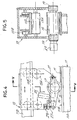
- 11D is indicated the upper cross member along which the carriage 13 slides. The above-mentioned carriage, according to FIGS. 4 and 5, is engaged in the cross member 11D by means of lower wheels or rollers 13A and upper wheels 13B.
- the pressure roller or cylinder 15 is mounted by means of supports 17 on a pair of levers 19 which are articulated at 21 to the structure of the carriage 13.
- the pressure roller or cylinder 15 is coupled to a motor and braking group generally indicated by 23, equipped with a suitable reducer; group 23 is able to actuate the rotating cylinder in both directions with an inversion which can be accompanied by a mechanical or electromagnetic braking action.
- the group 23 can be placed outside one of the levers 19.
- the levers 19 are urged to exert pressure towards the surface of the work surface 11B and therefore to act on the material M by means of cylinder-piston thrust systems 25.
- the angular amplitude of the levers 19 around the joints 21 towards the plane of work 11B is limited by the presence of rods 27 which, by passing through suitable seats drilled in the carriage 13, have adjustment sleeves 29 screwed onto the rods 27 and capable of stopping the levers 19 in a position such as a stop be created and that an adjustable and desired spacing of the pressure roller or cylinder of the worktop 11B is obtained.
- the setting depends on the thickness S of the material M in work, or better still on the final thickness So which will be reached by the material M.
- At least one of the levers 19 is capable of acting on a switch 31 which is predisposed to control the reversal of the movement of the carriage and the reversal of the direction of rotation of the pressure roller or cylinder 15 in accordance with the direction of movement of the carriage 13; reversing the direction of rotation of the cylinder 15 can be facilitated by a temporary braking action.
- the switch can be adjustable depending on the thickness of the material.
- the pressure roller or cylinder acts on the material M
- the working pressure is exerted by the push cylinders 25.
- the cylinder 15 loses contact with the material M, it can undergo only a small stroke of lowering towards the work surface 11B, this stroke being limited by the stop represented by the adjustment sleeves 29; the consecutive and limited movement of the levers 19 causes the switch 31 to start operating and in this way reversing the movement of the carriage and the rotation of the pressure roller or cylinder 15.
- the cylinder 15 thus quickly comes back into contact with material M without slipping on it and without damage from the edge of the material itself.
- the substantial difference between traditional machines and the machine according to the invention consists in the fact that the pressure roller or cylinder 15 is kept away from the work surface 11B and it is rotated and braked by its own motor system 23 at the most. less when it is not in contact on the material M to be rolled, the rotation and the reversal of the direction of rotation of the roller or cylinder being no longer conditioned by the contact between roller and work surface.
- This motor system 23 of the roller or cylinder 15 has the function of slowing and stopping the roller when it leaves the working material and reverses the direction of rotation before causing it to rise again on the material M, by imposing a tangential speed roughly corresponding to that of translation of the carriage.
- roller or cylinder 15 does not come into contact with the work surface 11B when it descends from the leather and the roller itself will no longer descend from the value So, equal to the thickness of the material deformed, but considerably less.
- the roller or cylinder 15 comes back into contact with the material M to be rolled, it is already rotating at a peripheral speed equal to that of translation of the carriage, so that it does not cause any displacement of the material M but it rises on it and it should only be lifted in small quantities.
Landscapes
- Engineering & Computer Science (AREA)
- Manufacturing & Machinery (AREA)
- Mechanical Engineering (AREA)
- Chemical & Material Sciences (AREA)
- Organic Chemistry (AREA)
- Metal Rolling (AREA)
- Soil Working Implements (AREA)
- Milling, Drilling, And Turning Of Wood (AREA)
Applications Claiming Priority (2)
| Application Number | Priority Date | Filing Date | Title |
|---|---|---|---|
| IT8809441A IT1224977B (it) | 1988-07-05 | 1988-07-05 | Macchina cilindratrice per il trattamento di cuoio, pelli ed altro escludendo la generazione di scarti ai bordi |
| IT944188 | 1988-07-05 |
Publications (3)
| Publication Number | Publication Date |
|---|---|
| EP0351379A2 EP0351379A2 (fr) | 1990-01-17 |
| EP0351379A3 EP0351379A3 (fr) | 1991-09-04 |
| EP0351379B1 true EP0351379B1 (fr) | 1995-09-27 |
Family
ID=11130191
Family Applications (1)
| Application Number | Title | Priority Date | Filing Date |
|---|---|---|---|
| EP89830307A Expired - Lifetime EP0351379B1 (fr) | 1988-07-05 | 1989-07-04 | Machine à cylindrer pour le traitement de cuir, peaux et autres en évitant la formation de déchets aux bords |
Country Status (4)
| Country | Link |
|---|---|
| EP (1) | EP0351379B1 (it) |
| DE (1) | DE68924379T2 (it) |
| ES (1) | ES2077588T3 (it) |
| IT (1) | IT1224977B (it) |
Family Cites Families (3)
| Publication number | Priority date | Publication date | Assignee | Title |
|---|---|---|---|---|
| DE637551C (de) * | 1934-12-02 | 1936-10-30 | Badische Maschinenfabriku Eise | Karrenlederwalze |
| FR1106805A (fr) * | 1954-07-13 | 1955-12-23 | D App Modernes Soc Ind De Cons | Machine à brillanter et à repasser les fourrures |
| AT258450B (de) * | 1964-06-03 | 1967-11-27 | Strojosvit Np | Steuereinrichtung zum selbsttätigen Reversieren eines Wagens samt Walze an Leder-Brückenwalzmaschinen |
-
1988
- 1988-07-05 IT IT8809441A patent/IT1224977B/it active
-
1989
- 1989-07-04 EP EP89830307A patent/EP0351379B1/fr not_active Expired - Lifetime
- 1989-07-04 ES ES89830307T patent/ES2077588T3/es not_active Expired - Lifetime
- 1989-07-04 DE DE68924379T patent/DE68924379T2/de not_active Expired - Fee Related
Also Published As
| Publication number | Publication date |
|---|---|
| IT1224977B (it) | 1990-10-30 |
| DE68924379D1 (de) | 1995-11-02 |
| IT8809441A0 (it) | 1988-07-05 |
| EP0351379A3 (fr) | 1991-09-04 |
| DE68924379T2 (de) | 1996-03-21 |
| EP0351379A2 (fr) | 1990-01-17 |
| ES2077588T3 (es) | 1995-12-01 |
Similar Documents
| Publication | Publication Date | Title |
|---|---|---|
| JPH01160849A (ja) | 積層窓ガラスの組立て装置 | |
| CN217668424U (zh) | 一种钢格板生产用修边装置 | |
| FR2494156A1 (fr) | Mecanisme de reperage, de positionnement et d'immobilisation de palettes pour machine transfert a postes multiples | |
| FI79258C (fi) | Fanersvarv. | |
| EP0351379B1 (fr) | Machine à cylindrer pour le traitement de cuir, peaux et autres en évitant la formation de déchets aux bords | |
| FR2478002A1 (fr) | Vehicule sans conducteur a commande de vitesse | |
| FR2510460A1 (fr) | Dispositif pour perforer ou decouper des feuilles minces | |
| EP0389317B1 (fr) | Positionnement d'une feuille de verre défilant sur un convoyeur | |
| WO2000005086A1 (fr) | Dispositif pour la pose d'un joint sur une carrosserie de vehicule et son procede de mise en oeuvre | |
| EP0084509B1 (fr) | Mécanisme d'entrainement réversible à vitesse variable des convoyeurs d'un laminoir à pâte | |
| FR2635094A1 (fr) | Procede de commande ou de regulation de bandes de materiau et jeu de rouleaux pour la mise en oeuvre de ce procede | |
| EP0018868B1 (fr) | Machine pour le refendage de brames par oxycoupage | |
| CA1052346A (en) | Apparatus for coiling striplike material | |
| FR2660226A1 (fr) | Outil de robot pour la pose d'un joint annulaire. | |
| US4892608A (en) | Automatic transverse splicing device for uncured elastomeric sheet material | |
| EP0071541B1 (fr) | Procédé et machine pour le façonnage des arêtes de vitrages | |
| EP0301983A1 (fr) | Machine pour poser le cordon formant joint d'étanchéité entre les deux plaques de verre d'une double vitrage rectangulaire ou carré | |
| FR2629448A1 (fr) | Appareillage pour decouper une piece en un materiau du type verre ou ceramique le long d'une ligne incisee | |
| FR2501098A1 (fr) | Machine pour le decoupage de rouleaux de tissu | |
| FR2574431A1 (fr) | Applicateur de peaux assiste par une energie exterieure | |
| FR2846266A1 (fr) | Dispositif et procede pour poncer un fut en bois | |
| EP0290344B1 (fr) | Procédé et dispositif pour le calandrage des vitrages feuilletés | |
| FR2532951A1 (fr) | Echarneuse continue pour tannerie | |
| RU2068314C1 (ru) | Устройство для отгибки и задачи конца полосы рулона | |
| FR2586707A1 (fr) | Dispositif d'entrainement d'une peau, adaptable sur une machine de tannerie |
Legal Events
| Date | Code | Title | Description |
|---|---|---|---|
| PUAI | Public reference made under article 153(3) epc to a published international application that has entered the european phase |
Free format text: ORIGINAL CODE: 0009012 |
|
| AK | Designated contracting states |
Kind code of ref document: A2 Designated state(s): DE ES FR |
|
| PUAL | Search report despatched |
Free format text: ORIGINAL CODE: 0009013 |
|
| AK | Designated contracting states |
Kind code of ref document: A3 Designated state(s): DE ES FR |
|
| 17P | Request for examination filed |
Effective date: 19911218 |
|
| 17Q | First examination report despatched |
Effective date: 19931129 |
|
| GRAA | (expected) grant |
Free format text: ORIGINAL CODE: 0009210 |
|
| AK | Designated contracting states |
Kind code of ref document: B1 Designated state(s): DE ES FR |
|
| REF | Corresponds to: |
Ref document number: 68924379 Country of ref document: DE Date of ref document: 19951102 |
|
| REG | Reference to a national code |
Ref country code: ES Ref legal event code: FG2A Ref document number: 2077588 Country of ref document: ES Kind code of ref document: T3 |
|
| PLBE | No opposition filed within time limit |
Free format text: ORIGINAL CODE: 0009261 |
|
| STAA | Information on the status of an ep patent application or granted ep patent |
Free format text: STATUS: NO OPPOSITION FILED WITHIN TIME LIMIT |
|
| 26N | No opposition filed | ||
| PGFP | Annual fee paid to national office [announced via postgrant information from national office to epo] |
Ref country code: FR Payment date: 20000630 Year of fee payment: 12 |
|
| PGFP | Annual fee paid to national office [announced via postgrant information from national office to epo] |
Ref country code: ES Payment date: 20000712 Year of fee payment: 12 |
|
| PGFP | Annual fee paid to national office [announced via postgrant information from national office to epo] |
Ref country code: DE Payment date: 20000922 Year of fee payment: 12 |
|
| PG25 | Lapsed in a contracting state [announced via postgrant information from national office to epo] |
Ref country code: ES Free format text: LAPSE BECAUSE OF NON-PAYMENT OF DUE FEES Effective date: 20010705 |
|
| PG25 | Lapsed in a contracting state [announced via postgrant information from national office to epo] |
Ref country code: FR Free format text: LAPSE BECAUSE OF NON-PAYMENT OF DUE FEES Effective date: 20020329 |
|
| PG25 | Lapsed in a contracting state [announced via postgrant information from national office to epo] |
Ref country code: DE Free format text: LAPSE BECAUSE OF NON-PAYMENT OF DUE FEES Effective date: 20020501 |
|
| REG | Reference to a national code |
Ref country code: FR Ref legal event code: ST |
|
| REG | Reference to a national code |
Ref country code: ES Ref legal event code: FD2A Effective date: 20020810 |