EP0350149A2 - Verfahren zum Aufrechterhalten der richtigen Zeit in einem verteilten Verarbeitungssystem - Google Patents
Verfahren zum Aufrechterhalten der richtigen Zeit in einem verteilten Verarbeitungssystem Download PDFInfo
- Publication number
- EP0350149A2 EP0350149A2 EP89304046A EP89304046A EP0350149A2 EP 0350149 A2 EP0350149 A2 EP 0350149A2 EP 89304046 A EP89304046 A EP 89304046A EP 89304046 A EP89304046 A EP 89304046A EP 0350149 A2 EP0350149 A2 EP 0350149A2
- Authority
- EP
- European Patent Office
- Prior art keywords
- time
- node
- local clock
- local
- clerk
- Prior art date
- Legal status (The legal status is an assumption and is not a legal conclusion. Google has not performed a legal analysis and makes no representation as to the accuracy of the status listed.)
- Withdrawn
Links
- 238000000034 method Methods 0.000 title claims abstract description 97
- 238000012545 processing Methods 0.000 title claims abstract description 47
- 230000004044 response Effects 0.000 claims description 33
- 230000000875 corresponding effect Effects 0.000 claims 28
- 229940035564 duration Drugs 0.000 claims 2
- 238000010586 diagram Methods 0.000 description 12
- 230000001934 delay Effects 0.000 description 8
- 238000004891 communication Methods 0.000 description 6
- 230000006854 communication Effects 0.000 description 6
- 230000008569 process Effects 0.000 description 5
- 241000238876 Acari Species 0.000 description 4
- 230000003247 decreasing effect Effects 0.000 description 4
- 101100172132 Mus musculus Eif3a gene Proteins 0.000 description 3
- 238000012360 testing method Methods 0.000 description 3
- 230000009471 action Effects 0.000 description 2
- 230000001174 ascending effect Effects 0.000 description 2
- 230000005540 biological transmission Effects 0.000 description 2
- 230000008859 change Effects 0.000 description 2
- 230000000694 effects Effects 0.000 description 2
- 230000006870 function Effects 0.000 description 2
- 229940036310 program Drugs 0.000 description 2
- 230000001360 synchronised effect Effects 0.000 description 2
- 230000006399 behavior Effects 0.000 description 1
- 238000012937 correction Methods 0.000 description 1
- 239000013078 crystal Substances 0.000 description 1
- 238000001514 detection method Methods 0.000 description 1
- 238000007689 inspection Methods 0.000 description 1
- 230000007257 malfunction Effects 0.000 description 1
- 230000000737 periodic effect Effects 0.000 description 1
- 238000012546 transfer Methods 0.000 description 1
Images







Classifications
-
- H—ELECTRICITY
- H04—ELECTRIC COMMUNICATION TECHNIQUE
- H04J—MULTIPLEX COMMUNICATION
- H04J3/00—Time-division multiplex systems
- H04J3/02—Details
- H04J3/06—Synchronising arrangements
- H04J3/0635—Clock or time synchronisation in a network
- H04J3/0638—Clock or time synchronisation among nodes; Internode synchronisation
- H04J3/0658—Clock or time synchronisation among packet nodes
- H04J3/0661—Clock or time synchronisation among packet nodes using timestamps
- H04J3/0667—Bidirectional timestamps, e.g. NTP or PTP for compensation of clock drift and for compensation of propagation delays
Definitions
- the present invention relates to distributed processing systems, and specifically to a method of maintaining a correct time in a plurality of nodes of a distributed processing system.
- LAN Local Area Networks
- Fig. 1 One such distributed data processing system network 29 is shown in Fig. 1.
- the network consists of multiple nodes 30 which pass information along connecting lines 32.
- the connecting lines 32 may be twisted-pair wires, coaxial cables, or the like.
- the nodes 30 may be any of various types of devices hooked to the network, such as VAXclusters provided by Digital Equipment Corporation, microcomputers, intelligent workstations, mainframe computers or the like.
- All nodes in the network 29 contain software responsible for organizing and coordinating the flow of information between the nodes.
- One type of such software is dedicated to the mechanics of establishing a signal connection between nodes, of transmitting information between nodes, and of ending the connection when the information transmittal is complete.
- Such software operates according to one of a variety of communication protocols, such as Digital Network Architecture (DNA) or Open System Interconnection (OSI), which are well known in the art and will not be described herein.
- a second type of software in the nodes is dedicated, not to the mechanics of information transmittal, but to generating the information being transmitted, i.e., to application programs.
- application programs include word processors, mail programs, data base managers, etc.
- a third type of software in the nodes provides an easy-to-use interface between the application programs and various other hardware or software.
- Software programs of this third type are called “clerks,” “clerk software,” or “clerk programs” because they handle the details of information transfer for the application programs.
- Application programs interfacing with clerks are called “clients,” “client software,” or “client programs” because the application programs are being served by the clerks.
- Nodes containing clerk software are called clerk nodes.
- Fig. 2 shows a clerk program 40 in a memory 44 of a node 41.
- Clerk program 40 provides an interface between the network via lines 32 and an application program 42, which is also in memory 44 of node 41.
- Clerk program 40 which is executed by a processor 46 in the node 41, transmits and receives information to and from network 29 via lines 32.
- Clerk program 40 communicates with application program 42 via locations (not shown) in memory 44 under control of application program 42.
- Many types of clerk programs similar to clerk program 40 may exist to handle the various needs of application programs.
- Fig. 2 also shows a local clock 48 of node 41.
- Local clock 48 is incremented regularly (if it is digital) or increased at a regular rate (if it is analog) to keep what is called “local time” for node 41. This incrementing is accomplished by an increment circuit 49.
- Local clock 48 is accessed, i.e., set and read, by clerk program 40 in node 41.
- Clerk program 40 also serves as an interface to local clock 48 for application program 42.
- clerk program 40 of Fig. 2 is called a "time service" clerk because it services requests for the local time from application program 42.
- the network of Fig. 1 uses a method called “carrier-sensing multiple access with collision detection” (CSMA/CD) as defined in IEEE Standard 802.3.
- CSMA/CD carrier-sensing multiple access with collision detection
- all nodes on the network are of equal importance.
- a node 30 can "send" information on the network only when no other node is trying to send information. If a node tries to send information at the same time that another node is also trying to send information, each node will wait a randomly-determined period of time and then attempt to resend its information. Since the period of time each node waits before attempting a resend is randomly determined, it is probable that both resends will be successful.
- Every node on the CSMA/CD network "listens" to all information sent over the network. If any node "sees” information intended for that node, the node will receive the information and take appropriate action.
- Information passing between the nodes of the network is organized into packets. Each packet contains data or control information surrounded by control and routing information.
- Network 29 of Fig. 1 operates using the Ethernet standard for data transmission. This standard governs the protocol used in transmitting data at a low conceptual level. It is compatible with the OSI and DNA communications protocols.
- Packets on an Ethernet network may be sent using one of two basic methods: unicasting and multicasting.
- unicasting a packet is sent from a first node to a second node.
- the destination address field of the packet indicates that the packet is destined for a single node.
- multicasting a single node broadcasts information to multiple nodes and the destination address field of the packet indicates that the packet is destined for a group of nodes.
- UTC Universal Coordinated Time
- Baux International Time Bureau
- PDT Pacific Daylight Time
- a clock is simply a device that provides a measure of UTC.
- the UTC time standard runs at a rate that is almost constant since it is based on ultra-stable atomic clocks.
- UT1 is inferred from astronomical observations. To keep UTC and UT1 approximately equal, occasional corrections of exactly one second -- called "leap" seconds -- are inserted into the UTC time scale when necessary.
- C i of a digital clock is given by:
- a clock is said to be monotonic if its measure of time is never decreasing, i.e., if C(i,t2) ⁇ C(i,t1) for t2 > t1.
- the resolution of a clock is the maximum time interval that can elapse without there being any change in the value of the clock.
- the resolution is denoted by p.
- ⁇ ij (t)
- I(i,t)
- a time interval is said to be correct if ⁇ W(i,t) ⁇ ⁇ t ⁇ ⁇ W(i,t) ⁇ , i.e., the interval contains UTC.
- a set of M local clocks is said to be synchronized if the clocks' intervals overlap, i.e., W(1,t)/) W(2,t),..., W(M,t) ⁇ 0. If the clocks are correct, they must be synchronized.
- clocks Two basic types of clocks exist: clocks that obtain time from an external source, such as radio signals, and clocks that are self-contained, such as crystal clocks.
- Clocks of the first type measure UTC with a known bound on the inaccuracy which depends on the propagation delay of the radio signal and implementation specific details. If operating correctly, the time and inaccuracy reported by clocks of the first type define an interval that contains the instantaneous value of UTC.
- Clocks of the second type supply the time in the form of a scalar and there is no inherent notion of inaccuracy. However, clocks of the second type do have bounds on their drifts, which is denoted by ⁇ max.
- Time in a data processing system, is used in at least three ways.
- a first use is to time and order events. In many processes performed by data processing systems (for example, event logging), it is desirable to be able to determine an order of occurrence for several events.
- a second use for time in a data processing system is to determine an interval of time that has elapsed between two events. Examples include system timeouts, Ethernet packet lifetimes, and I/O timeouts.
- a third use for time in a data processing system is to schedule future execution of events. If an event is to begin execution at a time near a scheduled time, an inaccuracy of the clock must be known and bounded within certain predetermined limits.
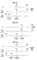
- node A and node B of a distributed processing system are to perform different steps of the following process at UTC times time1 and time2, respectively, UTC time1: copy file1 to file2 (by node A) UTC time2: copy file3 to file1 (by node B) where UTC time1 precedes UTC time2.
- UTC time1 copy file1 to file2 (by node A)
- UTC time2 copy file3 to file1 (by node B) where UTC time1 precedes UTC time2.
- the order of performance of the steps is critical.
- the local clock of node B may reach a local time2 before the local clock of node A reaches a local time1.
- the local clock of node B may have been mis-set at some previous time. Therefore, even though the local clock of node B is being incremented at correct intervals, local time2 of node B precedes local time1 of node A. Alternately, as shown in the timing diagram of Fig.
- the amount by which the local clock of node B is being incremented may be larger than the amount by which the amount by which node A is being incremented. Again, such a condition will cause local time2 of node B to precede local time1 of node A.
- the present invention overcomes the problems and disadvantages of the prior art by providing correct time from server nodes to clerk nodes at the request of the clerk nodes.
- the invention comprises a method for maintaining correct time in a clerk node in a distributed processing system also containing a plurality of server nodes.
- the clerk and server nodes are connected together and the server nodes provide time information to the system.
- Each of the nodes includes a local clock keeping a local time and each of the local clocks has a local drift value associated therewith representing a bound on the rate at which that local time deviates from a correct time value.
- the method comprises the steps performed by the clerk node of: requesting an updated time interval from at least one of the server nodes when the local inaccuracy of the local clock of the clerk node exceeds a predetermined maximum inaccuracy value; noting a request time according to the local clock of the clerk node when the clerk node requests the updated time interval; receiving from the server nodes respective updated time interval representations and corresponding delay values; noting, for each receipt of the updated time interval representations and corresponding delay values, a different response time according to the local clock of the clerk node; calculating a correct time interval from the received updated time interval representations, the received delay values, the noted request time, the noted response times, and the resolution value of the local clock of the clerk node, wherein the correct time is contained within said calculated correct time interval; and adjusting the local time kept by the local clock of the clerk node according to the calculated correct time interval.
- the invention further comprises a method for maintaining a correct time in a clerk node including the steps performed by the server node of: receiving a request for an updated time interval from another node when the local inaccuracy of the local clock of the other node exceeds a predetermined maximum inaccuracy value; noting a receipt time according to the local clock of the server node when the server node receives the request from the other node; calculating a delay value from the noted receipt time; calculating an updated time interval representation from the local time of the local clock of the server node and the inaccuracy of the local clock of the server node; and sending the updated time interval representation and the corresponding delay value to the other node.
- the method of the present invention is preferably carried out by data processing hardware executing a plurality of software programs. That hardware is preferably contained in nodes of a network such as network 29 shown in Fig. 1. As shown in Fig. 2, a node 41 which executes clerk program 40 is called a clerk node. The purpose of clerk node 41 is to service requests for a local time of local clock 48. As explained above, information passes from the connecting lines 32 into the clerk node 41 and to clerk program 40 executing on clerk node 41. Clerk program 40 updates its local clock 48 based on information received over lines 32 and, in response to requests from application program 42, reads the local time from local clock 48 and supplies it to application program 42.
- other nodes of the network execute similar software programs to clerk program 40, and supply time information to other application programs.
- server nodes execute software programs called server programs.
- Server programs send time information to clerk and server nodes over lines 32.
- time maintainer nodes also called time maintainers
- time provider nodes also called time providers
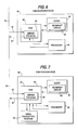
- Fig. 6 shows an embodiment of a time maintainer node 80.
- Time maintainer node 80 is connected to the network via lines 32. Similar to clerk node 40, time maintainer node 80 contains a processor 82 and a local clock 84.
- Local clock 84 contains an incrementation circuit 88 for periodically increasing the local time of local clock 84 by a predetermined resolution value.
- processor 82 Upon receiving a request for an updated time from a clerk node over the network, processor 82 executes a server program 86, which is stored in a memory 87 (preferably RAM) of time maintainer node 80. Server program 86 sends time information from server node 80's local clock 84 a to requesting clerk node over the network.
- server program 86 sends time information from server node 80's local clock 84 a to requesting clerk node over the network.
- Some time maintainer nodes may also include a battery back-up clock and non-volatile memory.
- the non-volatile memory stores a base local time and inaccuracy at a time T r , which can be recovered in case of system failure.
- the battery back-up clock continues keeping a local time during system failure.
- Fig. 7 shows a second type of server node 80′ called a time provider node.
- time provider node 80′ contains a processor 82′ and a local clock 84′.
- a server program 86′ which is stored in a memory 87′ of the time provider node 80′ and executed by processor 82′ of the node 80′, sends time information from the local clock 84′ over the network upon receiving a request from a clerk node.
- a requesting clerk node does not perceive any difference between time maintainer node 80 and time provider node 80′.
- Clerk programs use identical protocols to communicate with both types of nodes and the information received by a clerk program from both types of server nodes preferably has the same format.
- Time maintainer node 80 updates its local clock using the same method as clerk nodes, which is described in detail below.
- Time provider 80′ updates its local clock 84′ by accessing an external time source.
- time provider node 80′ contains a radio transmitter/receiver 94 which is used to receive time signals from a UTC broadcasting source, such as the WWV in Denver, Colorado. These received time signals are used by server program 86′ to update local clock 84′ of time provider node 80′.
- time provider nodes could alternatively access some other independent time source outside the network that provided time information not contaminated by any system delays, drifts of the local clock, or other inaccuracies.
- a time provider node that cannot access its external source will alternately update its local clock using the same method as time maintainer and clerk nodes.
- a method according to this invention will be described with respect to clerk node 40 shown in Fig. 2, although it should be understood that a network using the present invention may include other clerk nodes operating according to the method described below.
- the description of the operation of clerk nodes in accordance with the present invention will be presented in two parts.
- the first part describes how a clerk maintains its local clock and knowledge of the inaccuracy of its clock.
- This first part includes the method by which a local clock of a clerk node is correctly and monotonically adjusted to compensate for drift.
- the second part describes how a clerk node resynchronizes (obtains a new estimate of the time from the server nodes).
- This second part describes under what circumstances a clerk resynchronizes, the protocol for obtaining time estimates from server nodes, and an algorithm for computing an optimal correct time interval from these estimates.
- a local clock such as local clock 48 of Fig. 2, preferably comprises a software register representing the current time.
- This register preferably is updated by incrementation circuit 49, which may comprise a service routine invoked by a hardware interrupt of a periodic timer. In such an embodiment, these interrupts are called "ticks.”
- the time between ticks determines the resolution p of the local clock, which, in a preferred embodiment, equals 10 ms.
- An interrupt service routine services tick interrupts and increments the local clock by p. By changing the amount of the increment while keeping the time between ticks constant, the clock drift can be artificially altered, causing local clock 48 to gain or lose time. Alternatively, one could alter the time between ticks while keeping the software increment at a predetermined value.
- Fig. 8 shows a flow chart for a procedure called "AdjustClk_Start,” which is executed at a "resynchronization time,” T r , to begin incrementing the local clock by a new incrementation value instead of by the predetermined value p.
- Fig. 9 shows a flow chart for a procedure called "AdjustClk_End,” which is executed at a time T r + D (where D is the duration for which the new incrementation value is used) to end incrementing the local clock by the new incrementation value and resume incrementing by p.
- and, in the preferred embodiment, adj ⁇ 1.) "I rate " represents a rate at which the inaccuracy of the local clock increases in response to the drift of the local clock. Under normal operation, I rate ⁇ max, i.e., I rate equals the maximum drift of the local clock. However, while the local clock is being adjusted I rate is decreased to compensate for the drift increment rate, k.
- a current time, T i is set to T r (Step 100).
- Step 104 If T r is equal to T a (Step 104), then the local clock is already set correctly and no further adjustment is needed. If T r is not equal to T a , however, and if T a is greater than T r (Step 106), then k, the rate at which to alter the drift of the local clock is positive (Step 108) so that the local clock will gain time. Otherwise, k is negative (Step 110) so that the local clock will lose time.
- I rate the rate at which the inaccuracy of the local clock increases in response to the drift of the local clock, must be set to reflect the changed drift value of the local clock.
- I rate is calculated according to the following formula: (Step 112). Because, in the preferred embodiment, the absolute value of the adjustment rate,
- the procedure AdjustClk_End is then scheduled to execute at time T r + D (Step 116) and clock increment circuit 49 begins incrementing local clock 48 by (1 + k)p (Step 118).
- the Steps of Fig. 9 return local clock 48 to its regular incrementation procedure.
- I rate is negative, I i ′ ⁇ I i .
- Both T i ′ and I i ′ are stored in memory 44 to be used by clerk 40 in determining a time to resynchronize as described below.
- Step 128 the amount to alter the clock's drift, k, is set to zero because the clock adjusting procedure is done. Similarly, the rate of increase of the inaccuracy is reset to its original value of ⁇ max in Step 130.
- the preferred embodiment computes the next time to resynchronize, T, according to the following rule (where "max” is a function that selects a maximum of two values and "Synchold” is a predetermined value representing the shortest time allowed between resynchronizations in the preferred embodiment).
- T T a + max(synchold, (I max - I a )/ ⁇ max. (I max - I a )/ ⁇ max represents a time when the inaccuracy of local clock 48 will equal or exceed I max .
- clerk program 40 obtains the time from a particular server node by making an explicit request to the server program of that node for the time and then waiting for a response.
- This method of access has two features. First, it makes it possible for a clerk to measure the delay incurred due to the communication protocol overhead and, hence, makes it possible to bound the inaccuracy of the received time. Second, it requires no specific underlying communications hardware.
- Fig. 10 is a time-space diagram of a request from a clerk, such as clerk program 40, and a response from a server program, such as server program 86 of time maintainer node 80 or server program 86′ of time provider node 80′.
- the value of the clerk's clock at time t i is denoted by C c (t i ) and the value of the server's clock at time t i is denoted by C s (t i ).
- a double arrow denotes a message transmission and a single arrow denotes a message reception.
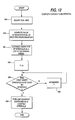
- Fig. 11 is a flow chart of a preferred method performed by the clerk node for making the request illustrated by Fig. 10.
- the clerk decides that it is time to resynchronize (Step 200)
- the clerk reads its local clock which returns the value C c (t1) (Step 202).
- the clerk then initiates a request to the server (Step 204) the request is transmitted at time t2 after an unknown sending delay S c , as shown in Fig. 10, and the request is received by the server at time t4 after unknown delays of cs and r s .
- the clerk waits until it receives a response from the server (Step 208) in the form of an interval [u,v], and a delay w.
- the interval [u,v] is represented by a midpoint value and an inaccuracy value. Other embodiments could represent [u,v] by two endpoints.
- the response from the server is received at time C c (t8) (Step 210) after incurring random delays similar to those of the request, namely S s , sc , and r c .
- the time seen by the clerk at t1 can be bounded by C s (t4) + w - (C c (t8) - C c (t1)) ⁇ C s (t1) ⁇ C s (t4), but it can never be known exactly.
- the effect of the drift of the clerk with respect to the server over the time period of the exchange is neglected.
- the interval bounding C s (t1) can be reduced.
- the timestamp C c (t8) actually corresponds to the value of local clock 48 in the range [C c (t8),C c (t8) + p], where p is the resolution of local clock 48.
- W(i,t4) [u,v] rather than a scalar value.
- U(i,t1) [u + w - (C c (t8) + p - C c (t1)),v]
- the clerk complies U(i,t i ) in this manner (Step 212).
- the value w which is returned with the time to the clerk, corresponds to the known delay at the server after the time which is reported to the clerk (and hence, it may include any deterministic component of S s ).
- the server does not include any deterministic component of r s in the value of w returned as this delay occurs before t4.
- w should reflect the delay at the server as accurately as possible, but w should never be greater than the actual delay incurred.
- request and response packets may be lost or servers may become unavailable, a clerk waits only a predetermined time for a response to a request.
- Fig. 12 is a flow chart of the preferred method used by clerk program 40 in accordance with of the present invention to compute the smallest interval guaranteed to contain UTC.
- T r the value at the next resynchronization time
- Step 254 all the endpoints of the intervals U(j,T r ) are arranged into a list in ascending order.
- a counter, f representing the number of existing faulty servers is set to zero (Step 256) and the list is scanned in ascending order to find the first endpoint that is contained in at least M - f intervals (Step 258). This point, if found, is a lower endpoint of the smallest time interval containing UTC. If no such point is found then there are more than f faulty servers.
- the counter f is incremented (Step 260), control returns to Step 258, and a smaller number of intervals is scanned for a common endpoint.
- Step 258 If the lower endpoint is found (Step 258), then the list is scanned in descending order to find a second endpoint that is contained in at least M - f intervals (Step 262). This point is an upper endpoint of the smallest time interval containing UTC.
- Scanning the list for the first upper and lower endpoints is accomplished more easily if the elements of the list are marked as maximum end points or minimum end points depending on whether they correspond to ⁇ U(j,T r ) ⁇ or ⁇ U(j,T r ) ⁇ , respectively.
- Fig. 13 contains a flow chart describing a method for finding the lower endpoint of the best correct time interval efficiently. This method is used in Step 262 of Fig. 12.
- IntersectingInts represents a number of intervals containing a tentative minimum endpoint.
- MostInts represents number of intervals containing a current minimum endpoint.
- a third loop counter, i is initialized to "2" to indicate that the second list element is being considered as the tentative minimum endpoint.
- the first element in the ordered list of endpoints of Step 254 of Fig. 12 is designated as the current minimum endpoint by setting Minpoint to "1" (Step 270).
- the initial value of IntersectingInts indicates that only one interval thus far contains the tentative minimum endpoint indicated by the counter i.
- the initial value of MostInts indicates that the first endpoint in the list (designated by Minpoint) is contained in one interval.
- Step 272 If the ith list element is greater than the tentative minimum endpoint designated by Minpoint (Step 272), then the counter IntersectingInts is incremented (Step 274), and a test is performed to determine if the counter IntersectingInts is greater than the counter MostInts (Step 276). If yes, the counter MostInts is set to IntersectingInts, the number of intervals containing the ith list element is saved, and the current value of i is saved as the tentative minimum endpoint (Step 278). Otherwise, if IntersectingInts is not greater than MostInts, control passes to Step 282.
- Step 272 If the ith list element is not greater than the tentative minimum endpoint (Step 272), then the counter IntersectingInts is decremented (Step 280) and control passes to Step 282.
- Step 282 a test is performed to determine if more endpoints in the list have yet to be examined. If yes, i is incremented (Step 284) and Steps 272 through 282 are repeated to examine another endpoint. If no, then all of the 2M-1 elements in the list of endpoints have been checked and control passes to Step 286.
- Step 286 a test is performed to determine if an endpoint within M-f intervals has been found. If yes, a minimum endpoint has been found (Step 288). Otherwise, no endpoint is contained in at least M-f intervals (Step 290).
- a similar algorithm can be used to find the maximum endpoint of the best correct time, as required by Step 262 of Fig. 12, by searching the endpoint list in descending order.
- the result of the method of Figs. 12 and 13 is the time (with inaccuracy) that the clerk's clock should read when the clock value becomes T r , i.e., ⁇ T a ,I a >.
- a clerk preferably uses the times from all the servers that are available. Other embodiments, however, may use the times from fewer than all of the servers.
- Fig. 14 is a flow chart for making adjustments for leap seconds by clerk program 40. If a current time, T, of local clock 48 plus a current inaccuracy, I, of local clock 48 is midnight of either March 31, or June 30, September 30, or December 31 (Step 300) then the current inaccuracy, I, is incremented by "1" (Step 304). This adjustment is always performed whether or not a leap second actually occurs. Other embodiments may compensate for leap seconds only in response to a command from a human operator.
- a description of the operation of server nodes consists of four parts. These parts are: how servers initialize and operate; how time maintainer nodes periodically obtain a new time from other servers; how time maintainer nodes can be manually reset; and how servers periodically check for faulty servers.
- Fig. 15 is a flow chart performed by a server in responding to a clerk node's requests, as demonstrated in Fig. 10.
- a server waits until it receives a request from a clerk (Step 220) and notes a time of receipt C s (t4) (Step 222). This time of receipt is later than the actual arrival time of the request by r s .
- the server processes the request by computing its own inaccuracy at time C s (t4) and by noting a known component of delay w (Step 226).
- the server transmits the local time interval and w to the requesting clerk at time C s (t6) (Step 228). This action takes a time S s .
- delays r s and S s are random and unpredictable.
- a time provider initializes by obtaining the time from an external source. It then attempts to discover other servers, by means of the protocols described below, for the purpose of periodically checking for faulty servers.
- a time maintainer When a time maintainer initializes, it first attempts to discover other servers, as described below. If other servers are available, it obtains the time from them as if it were a clerk node. If no other servers are available (meaning that the initializing server is the first server to be started), but the time maintainer has a battery back-up clock and non-volatile memory in which T i and I i are stored (as shown in Fig. 6), the time maintainer sets its local clock to the time of the battery clock and restores T i and I i from the stored values.
- the timer maintainer If the timer maintainer does not have a battery clock, it waits either for other server nodes (such as time providers) to become available or for a command from a human operator to reset the time. In the latter case, the time maintainer simply accepts the new time without recourse to any consistency checks.
- server nodes such as time providers
- Time maintainers resynchronize periodically to compensate for the drift of their local clocks and to reduce the width of their time intervals.
- a time maintainer determines when to synchronize by the same method used by clerks, which is described in connection with Figs. 10-13.
- a time maintainer When resynchronizing, a time maintainer also performs the algorithm described below for detecting faulty servers and, in addition, adjusts its clock to the correct time in the same way that clerks do (see Figs. 8-9).
- time providers do not resynchronize to other servers because time providers obtain time from an external source. The inaccuracy of the time obtained by time providers is implementation specific because it depends on the hardware used to obtain the external time.
- a manual reset method exists in the preferred embodiment whereby the time can be updated by resetting the time at single time maintainer. To protect against a human operator erroneously supplying an incorrect value of time, the manual reset method requires the time interval supplied by the human operator to be contained in the local time interval of the server being reset.
- the manual reset method described below does not allow large changes to the current time kept by a local clock. It does, however, allow a human operator to reduce the inaccuracy of a local clock or to make small changes to the value of the clock.
- Fig. 16 shows a flow chart of the algorithm that a preferred embodiment of a time maintainer node executes in response to the receipt of manual reset request including a new time interval.
- the new time interval is denoted by ⁇ T m , I m > and the time at which the manual reset request is received, as measured by the local clock, is denoted by T u .
- Step 320 the correct time is computed as described in connection with Figs. 12 and 13 (Step 320).
- This Step determines the actual time ⁇ T a , I a > corresponding to the future instant at which the local clock will read T r .
- the interval ⁇ T m , I m >, which corresponds to local time T u is translated to its equivalent value ⁇ T′ m , I′ m >, corresponding to local time T r , according to the formula given above in connection with Step 252 of Fig. 12 (Step 326).
- Step 328 If ⁇ T′ m , I′ m > is not contained in the interval ⁇ T a , I a > (Step 328), the manual reset request is rejected and an error is noted (Step 330). Otherwise the request is accepted and control passes to Step 332 where T a is set to T′ m and I a is set to I′ m .
- procedure AdjustClk-Start shown in Fig. 8 is initiated to adjust the local clock of the time maintainer node (Step 334).
- the time maintainer must complete the adjustment accomplished by the Steps shown in Fig. 16 before resynchronizing to other servers. Otherwise, the manual reset request may not take effect. It is only necessary to reset a single time maintainer. All other time maintainers will conform to the new time once they resynchronize.
- the time kept by the nodes in a network is incorrect due to operator error or some catastrophic failure and not to failures in the servers themselves.
- the present invention employs epoch numbers which allow groups of servers to be decoupled, and which make it possible to introduce a new value of time into the distributed system by introducing it into one of the decoupled groups.
- each server is assigned an epoch number.
- Servers preferably include their epoch numbers in their responses to requests for the time. Clerks always ignore this parameter.
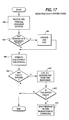
- a server resynchronizes or checks for faulty servers, it ignores servers with epoch numbers differ lengthyent from its own, as shown in Step 402 of Fig. 17, thereby decoupling that server from servers of a different epoch.
- a server epoch number can only be changed by a human operator. Whenever a new epoch number is assigned to a given server, that server must reinitialize according to the procedure described above. A human operator changes the epoch number at a single server and supplies it with the correct time if the server is a time maintainer node.
- the human operator can migrate the other servers to the new (correct) epoch by changing their epoch numbers, one at a time, to correspond to that of the new epoch.
- each server's epoch number is changed, it will reinitialize and obtain the correct time.
- each server notes any servers whose epoch numbers are different from its own.
- server nodes periodically check to see if other server nodes are faulty but operational.
- the method used is to obtain the time from all available servers, compute the best correct time interval, and see if any servers do not agree with the correct time.
- the time is obtained from all available servers including the time from the clock of the server node executing the method (Step 400).
- Time intervals obtained from servers of a different epoch (Step 402) than the executing server node (see below) are discarded and logged (Step 404).
- the correct time interval corresponding to the resynchronization time T r is computed using the algorithm presented in connection with the resynchronization of clerk nodes (Figs. 12-13), and the value of f, representing the number of faulty servers resulting in this interval, is recorded (Step 406). If the value of f is not zero, there are faulty servers (Step 408) and an event including the identification of all servers and their respective times is logged (Step 410). If the executing server's own time interval is not contained in the computed correct interval, then the executing server is faulty (Step 412). In this case, the executing server must refrain from responding to requests for the time until it has corrected itself (Step 414). A faulty time maintainer corrects itself by adjusting its clock as described above (for clerk nodes) in Figs. 8 and 9. A faulty timer provider attempts to correct itself by obtaining the correct time from the external reference.
- Time maintainers preferably execute the procedure of Fig. 17 whenever they resynchronize.
- Time providers preferably execute the procedure at predetermined intervals.
- time providers may include a local clock which is kept correct by periodically polling a device that receives the external signal (such as a WWV receiver).
- a time provider node For the purpose of accomodating leap seconds, such a time provider node must make adjustments for leap seconds using the method used by time maintainers and clerks. More specifically, at the time of a potential leap second as measured by T + I, the inaccuracy must be increased by one second by a method similar to that of Fig. 14.
Landscapes
- Engineering & Computer Science (AREA)
- Computer Networks & Wireless Communication (AREA)
- Signal Processing (AREA)
- Computer And Data Communications (AREA)
- Synchronisation In Digital Transmission Systems (AREA)
- Multi Processors (AREA)
Applications Claiming Priority (2)
| Application Number | Priority Date | Filing Date | Title |
|---|---|---|---|
| US07/213,746 US4894846A (en) | 1988-06-30 | 1988-06-30 | Method for maintaining a correct time in a distributed processing system |
| US213746 | 2002-08-06 |
Publications (2)
| Publication Number | Publication Date |
|---|---|
| EP0350149A2 true EP0350149A2 (de) | 1990-01-10 |
| EP0350149A3 EP0350149A3 (de) | 1992-10-28 |
Family
ID=22796338
Family Applications (1)
| Application Number | Title | Priority Date | Filing Date |
|---|---|---|---|
| EP19890304046 Withdrawn EP0350149A3 (de) | 1988-06-30 | 1989-04-24 | Verfahren zum Aufrechterhalten der richtigen Zeit in einem verteilten Verarbeitungssystem |
Country Status (5)
| Country | Link |
|---|---|
| US (1) | US4894846A (de) |
| EP (1) | EP0350149A3 (de) |
| JP (1) | JPH0251715A (de) |
| AU (1) | AU601904B2 (de) |
| CA (1) | CA1323109C (de) |
Cited By (4)
| Publication number | Priority date | Publication date | Assignee | Title |
|---|---|---|---|---|
| EP0613271A3 (de) * | 1993-02-22 | 1995-05-03 | Honeywell Inc | Verfahren und Anlage zur Zeit-Synchronisierung von Bus-LANs, mit hierarchischen Netzen. |
| US5436936A (en) * | 1990-08-14 | 1995-07-25 | Tecnomen Oy | Compensation of a clock operating error |
| WO2001020827A1 (de) * | 1999-09-13 | 2001-03-22 | Siemens Aktiengesellschaft | Anordnung zum synchronisieren von über ein kommunikationsnetz gekoppelten kommunikationssystemkomponenten |
| EP1729433A1 (de) * | 2005-05-31 | 2006-12-06 | Bosch Rexroth AG | Verfahren zur Laufzeitkorrektur in einer Kommunikationsstruktur |
Families Citing this family (36)
| Publication number | Priority date | Publication date | Assignee | Title |
|---|---|---|---|---|
| US5293374A (en) * | 1989-03-29 | 1994-03-08 | Hewlett-Packard Company | Measurement system control using real-time clocks and data buffers |
| US5440730A (en) * | 1990-08-09 | 1995-08-08 | Bell Communications Research, Inc. | Time index access structure for temporal databases having concurrent multiple versions |
| US5774377A (en) * | 1991-07-30 | 1998-06-30 | Hewlett-Packard Company | Method and apparatus for monitoring a subsystem within a distributed system for providing an archive of events within a certain time of a trap condition |
| US5386542A (en) * | 1991-10-31 | 1995-01-31 | International Business Machines Corporation | System for generating a time reference value in the MAC layer of an ISO/OSI communications model among a plurality of nodes |
| GB2271251B (en) * | 1992-10-01 | 1996-08-14 | Digital Equipment Int | Timer synchronisation system |
| US5694537A (en) * | 1995-07-31 | 1997-12-02 | Canon Information Systems, Inc. | Network device which selects a time service provider |
| US5781449A (en) * | 1995-08-10 | 1998-07-14 | Advanced System Technologies, Inc. | Response time measurement apparatus and method |
| US5748941A (en) * | 1995-11-09 | 1998-05-05 | Xerox Corporation | System and method for synchronizing control clocks for a modular printing system |
| US6134234A (en) * | 1996-07-19 | 2000-10-17 | Nokia Telecommunications Oy | Master-slave synchronization |
| US6125368A (en) * | 1997-02-28 | 2000-09-26 | Oracle Corporation | Fault-tolerant timestamp generation for multi-node parallel databases |
| US6078956A (en) * | 1997-09-08 | 2000-06-20 | International Business Machines Corporation | World wide web end user response time monitor |
| JP3323782B2 (ja) * | 1997-09-09 | 2002-09-09 | 株式会社日立製作所 | 情報の記録方法 |
| JP3348146B2 (ja) * | 1997-12-05 | 2002-11-20 | 株式会社日立製作所 | 通信制御装置 |
| US6748451B2 (en) | 1998-05-26 | 2004-06-08 | Dow Global Technologies Inc. | Distributed computing environment using real-time scheduling logic and time deterministic architecture |
| US6477571B1 (en) | 1998-08-11 | 2002-11-05 | Computer Associates Think, Inc. | Transaction recognition and prediction using regular expressions |
| US6357040B1 (en) * | 1998-10-21 | 2002-03-12 | Wildseed Limited | Usage characteristic based software customization |
| US6502062B1 (en) * | 1999-06-21 | 2002-12-31 | Lucent Technologies Inc. | System and method for scheduling data delivery using flow and stretch algorithms |
| US7062556B1 (en) * | 1999-11-22 | 2006-06-13 | Motorola, Inc. | Load balancing method in a communication network |
| US6708281B1 (en) * | 2000-07-10 | 2004-03-16 | Advanced Micro Devices, Inc. | Methods for providing estimates of the current time in a computer system including a local time source having one of several possible levels of trust with regard to timekeeping |
| US6742048B1 (en) | 2000-07-10 | 2004-05-25 | Advanced Micro Devices, Inc. | Multilevel network for distributing trusted time and delegating levels of trust regarding timekeeping |
| DE10206865C1 (de) * | 2002-02-18 | 2003-05-15 | Daimler Chrysler Ag | Reaktionszeit-Beschränkung eines Software-Prozesses |
| US7506023B2 (en) * | 2002-06-13 | 2009-03-17 | International Business Machines Corporation | Apparatus, system and method of relating time set on one computer system to time set on another computer system |
| US8724615B1 (en) | 2005-10-11 | 2014-05-13 | Atmel Corporation | Method and apparatus for generation of a system master timebase of a computing device using indirect signalling of timing information |
| US7899894B2 (en) | 2006-08-30 | 2011-03-01 | International Business Machines Corporation | Coordinated timing network configuration parameter update procedure |
| US7783913B2 (en) * | 2007-01-31 | 2010-08-24 | International Business Machines Corporation | Facilitating recovery in a coordinated timing network |
| US7797414B2 (en) * | 2007-01-31 | 2010-09-14 | International Business Machines Corporation | Establishing a logical path between servers in a coordinated timing network |
| US7783736B2 (en) | 2007-01-31 | 2010-08-24 | International Business Machines Corporation | Definition of an active stratum-1 server in a coordinated timing network |
| US9112626B2 (en) * | 2007-01-31 | 2015-08-18 | International Business Machines Corporation | Employing configuration information to determine the role of a server in a coordinated timing network |
| US8738792B2 (en) * | 2007-01-31 | 2014-05-27 | International Business Machines Corporation | Server time protocol messages and methods |
| US7689718B2 (en) * | 2007-01-31 | 2010-03-30 | International Business Machines Corporation | Channel subsystem server time protocol commands and system therefor |
| ATE536681T1 (de) * | 2007-10-04 | 2011-12-15 | Harman Becker Automotive Sys | Datennetzwerk mit zeitsynchronisationsmechanismus |
| US8416811B2 (en) * | 2008-04-10 | 2013-04-09 | International Business Machines Corporation | Coordinated timing network having servers of different capabilities |
| US7925916B2 (en) | 2008-04-10 | 2011-04-12 | International Business Machines Corporation | Failsafe recovery facility in a coordinated timing network |
| US20090307610A1 (en) * | 2008-06-10 | 2009-12-10 | Melonie Elizabeth Ryan | Method for a plurality of users to be simultaneously matched to interact one on one in a live controlled environment |
| US7873862B2 (en) * | 2008-10-21 | 2011-01-18 | International Business Machines Corporation | Maintaining a primary time server as the current time server in response to failure of time code receivers of the primary time server |
| CN102970125A (zh) * | 2012-10-25 | 2013-03-13 | 中兴通讯股份有限公司 | 近距离同步时间的方法及装置 |
Family Cites Families (6)
| Publication number | Priority date | Publication date | Assignee | Title |
|---|---|---|---|---|
| US4677614A (en) * | 1983-02-15 | 1987-06-30 | Emc Controls, Inc. | Data communication system and method and communication controller and method therefor, having a data/clock synchronizer and method |
| US4530091A (en) * | 1983-07-08 | 1985-07-16 | At&T Bell Laboratories | Synchronization of real-time clocks in a packet switching system |
| US4551833A (en) * | 1983-08-10 | 1985-11-05 | At&T Bell Laboratories | Distributed monitoring of packet transmission delay |
| JPS616953A (ja) * | 1984-06-21 | 1986-01-13 | Fujitsu Ltd | タイマ補正方式 |
| US4746920A (en) * | 1986-03-28 | 1988-05-24 | Tandem Computers Incorporated | Method and apparatus for clock management |
| JPS638813A (ja) * | 1986-06-27 | 1988-01-14 | Nec Corp | ロ−カルエリアネツトワ−クに於ける時刻統一方式 |
-
1988
- 1988-06-30 US US07/213,746 patent/US4894846A/en not_active Expired - Lifetime
-
1989
- 1989-04-24 EP EP19890304046 patent/EP0350149A3/de not_active Withdrawn
- 1989-05-19 AU AU35003/89A patent/AU601904B2/en not_active Ceased
- 1989-06-19 JP JP1156643A patent/JPH0251715A/ja active Pending
- 1989-06-29 CA CA000604308A patent/CA1323109C/en not_active Expired - Fee Related
Cited By (5)
| Publication number | Priority date | Publication date | Assignee | Title |
|---|---|---|---|---|
| US5436936A (en) * | 1990-08-14 | 1995-07-25 | Tecnomen Oy | Compensation of a clock operating error |
| EP0613271A3 (de) * | 1993-02-22 | 1995-05-03 | Honeywell Inc | Verfahren und Anlage zur Zeit-Synchronisierung von Bus-LANs, mit hierarchischen Netzen. |
| WO2001020827A1 (de) * | 1999-09-13 | 2001-03-22 | Siemens Aktiengesellschaft | Anordnung zum synchronisieren von über ein kommunikationsnetz gekoppelten kommunikationssystemkomponenten |
| US7085276B1 (en) | 1999-09-13 | 2006-08-01 | Siemens Aktiengesellschaft | System for synchronizing communications system components coupled via a communications network |
| EP1729433A1 (de) * | 2005-05-31 | 2006-12-06 | Bosch Rexroth AG | Verfahren zur Laufzeitkorrektur in einer Kommunikationsstruktur |
Also Published As
| Publication number | Publication date |
|---|---|
| US4894846A (en) | 1990-01-16 |
| AU3500389A (en) | 1990-05-17 |
| CA1323109C (en) | 1993-10-12 |
| EP0350149A3 (de) | 1992-10-28 |
| JPH0251715A (ja) | 1990-02-21 |
| AU601904B2 (en) | 1990-09-20 |
Similar Documents
| Publication | Publication Date | Title |
|---|---|---|
| EP0350149A2 (de) | Verfahren zum Aufrechterhalten der richtigen Zeit in einem verteilten Verarbeitungssystem | |
| US6199169B1 (en) | System and method for synchronizing time across a computer cluster | |
| US6665316B1 (en) | Organization of time synchronization in a distributed system | |
| CA2195459C (en) | Disciplined time scale generator for primary reference clocks | |
| EP1525693B1 (de) | Clock-synchronisationsmethode für fehlertolerante ethernet-netzwerke | |
| EP1280024B1 (de) | Uhrensynchronisation in einem verteilten System | |
| US5428645A (en) | Anonymous time synchronization method | |
| EP0135764B1 (de) | Taktsynchronisation in einem verteilten Rechnernetz | |
| US5887029A (en) | Method of scheduling spatially separated control events with an industrial controller | |
| Cristian et al. | Probabilistic internal clock synchronization | |
| US5327468A (en) | Synchronization of time-of-day clocks in a distributed processing network system | |
| EP1239620A2 (de) | Relative Zeitsynchronisation zwischen drei oder mehr System | |
| US20040223515A1 (en) | Method and apparatus for the synchronization of a system time of a communications network with a clock reference | |
| EP0539704A1 (de) | Konstruktion für die genaue Verteilung eines Zeitreferenzwertes auf einem ringförmigen lokalen Netzwerk | |
| US5519726A (en) | Industrial controller with coordinated timing | |
| US6801951B1 (en) | System and method for fault-tolerant clock synchronization using interactive convergence | |
| GB2198018A (en) | Simultaneous data communication | |
| US6714611B1 (en) | Wireless network with user clock synchronization | |
| Kopetz et al. | A synchronization strategy for a time-triggered multicluster real-time system | |
| US5925107A (en) | Verifying a time-of-day counter | |
| EP1198911A1 (de) | Synchronisierungsverfahren und -system für taktquellen bei insbesondere paketvermittelnden kommunikationssystemen | |
| Mills | Experiments in network clock synchronization | |
| Thambidurai et al. | Clock synchronization in MAFT | |
| JPH11223687A (ja) | 複数計算機間の内部時計同期方式 | |
| Chakravarthi et al. | A fine-grain clock synchronization mechanism for QoS based communication on myrinet |
Legal Events
| Date | Code | Title | Description |
|---|---|---|---|
| PUAI | Public reference made under article 153(3) epc to a published international application that has entered the european phase |
Free format text: ORIGINAL CODE: 0009012 |
|
| 17P | Request for examination filed |
Effective date: 19890516 |
|
| AK | Designated contracting states |
Kind code of ref document: A2 Designated state(s): DE FR GB IT NL |
|
| PUAL | Search report despatched |
Free format text: ORIGINAL CODE: 0009013 |
|
| AK | Designated contracting states |
Kind code of ref document: A3 Designated state(s): DE FR GB IT NL |
|
| 17Q | First examination report despatched |
Effective date: 19960627 |
|
| GRAG | Despatch of communication of intention to grant |
Free format text: ORIGINAL CODE: EPIDOS AGRA |
|
| GRAG | Despatch of communication of intention to grant |
Free format text: ORIGINAL CODE: EPIDOS AGRA |
|
| GRAG | Despatch of communication of intention to grant |
Free format text: ORIGINAL CODE: EPIDOS AGRA |
|
| GRAH | Despatch of communication of intention to grant a patent |
Free format text: ORIGINAL CODE: EPIDOS IGRA |
|
| GRAH | Despatch of communication of intention to grant a patent |
Free format text: ORIGINAL CODE: EPIDOS IGRA |
|
| STAA | Information on the status of an ep patent application or granted ep patent |
Free format text: STATUS: THE APPLICATION IS DEEMED TO BE WITHDRAWN |
|
| 18D | Application deemed to be withdrawn |
Effective date: 19991101 |