EP0349918B1 - Disposition de glissière, en particulier pour siège de voiture - Google Patents
Disposition de glissière, en particulier pour siège de voiture Download PDFInfo
- Publication number
- EP0349918B1 EP0349918B1 EP89111952A EP89111952A EP0349918B1 EP 0349918 B1 EP0349918 B1 EP 0349918B1 EP 89111952 A EP89111952 A EP 89111952A EP 89111952 A EP89111952 A EP 89111952A EP 0349918 B1 EP0349918 B1 EP 0349918B1
- Authority
- EP
- European Patent Office
- Prior art keywords
- rail
- teeth
- toothed
- slide
- border
- Prior art date
- Legal status (The legal status is an assumption and is not a legal conclusion. Google has not performed a legal analysis and makes no representation as to the accuracy of the status listed.)
- Expired - Lifetime
Links
- 239000011248 coating agent Substances 0.000 claims description 15
- 238000000576 coating method Methods 0.000 claims description 15
- 229910052782 aluminium Inorganic materials 0.000 claims description 11
- XAGFODPZIPBFFR-UHFFFAOYSA-N aluminium Chemical compound [Al] XAGFODPZIPBFFR-UHFFFAOYSA-N 0.000 claims description 11
- 239000002966 varnish Substances 0.000 claims description 7
- 229910000831 Steel Inorganic materials 0.000 claims description 3
- 239000010959 steel Substances 0.000 claims description 3
- 229920003002 synthetic resin Polymers 0.000 claims description 3
- 239000000057 synthetic resin Substances 0.000 claims description 3
- 239000000843 powder Substances 0.000 claims description 2
- 238000007767 slide coating Methods 0.000 claims 7
- 239000004411 aluminium Substances 0.000 claims 2
- 238000005299 abrasion Methods 0.000 description 7
- 239000000463 material Substances 0.000 description 7
- 230000009471 action Effects 0.000 description 2
- 230000008901 benefit Effects 0.000 description 2
- 238000011109 contamination Methods 0.000 description 2
- 238000006073 displacement reaction Methods 0.000 description 2
- 230000000694 effects Effects 0.000 description 2
- 238000009434 installation Methods 0.000 description 2
- 230000009191 jumping Effects 0.000 description 2
- 239000004922 lacquer Substances 0.000 description 2
- 238000004519 manufacturing process Methods 0.000 description 2
- 230000036316 preload Effects 0.000 description 2
- 230000001681 protective effect Effects 0.000 description 2
- 239000000853 adhesive Substances 0.000 description 1
- 230000001070 adhesive effect Effects 0.000 description 1
- 238000009749 continuous casting Methods 0.000 description 1
- 238000003618 dip coating Methods 0.000 description 1
- 239000000428 dust Substances 0.000 description 1
- 238000001125 extrusion Methods 0.000 description 1
- 230000002349 favourable effect Effects 0.000 description 1
- 239000000945 filler Substances 0.000 description 1
- 230000009969 flowable effect Effects 0.000 description 1
- 238000007654 immersion Methods 0.000 description 1
- 230000001771 impaired effect Effects 0.000 description 1
- 238000012423 maintenance Methods 0.000 description 1
- 230000007257 malfunction Effects 0.000 description 1
- 230000007246 mechanism Effects 0.000 description 1
- 239000007769 metal material Substances 0.000 description 1
- 239000003973 paint Substances 0.000 description 1
- 230000009467 reduction Effects 0.000 description 1
- 230000008439 repair process Effects 0.000 description 1
- 229920005989 resin Polymers 0.000 description 1
- 239000011347 resin Substances 0.000 description 1
- 230000000284 resting effect Effects 0.000 description 1
Images

Classifications
-
- B—PERFORMING OPERATIONS; TRANSPORTING
- B60—VEHICLES IN GENERAL
- B60N—SEATS SPECIALLY ADAPTED FOR VEHICLES; VEHICLE PASSENGER ACCOMMODATION NOT OTHERWISE PROVIDED FOR
- B60N2/00—Seats specially adapted for vehicles; Arrangement or mounting of seats in vehicles
- B60N2/02—Seats specially adapted for vehicles; Arrangement or mounting of seats in vehicles the seat or part thereof being movable, e.g. adjustable
- B60N2/04—Seats specially adapted for vehicles; Arrangement or mounting of seats in vehicles the seat or part thereof being movable, e.g. adjustable the whole seat being movable
- B60N2/06—Seats specially adapted for vehicles; Arrangement or mounting of seats in vehicles the seat or part thereof being movable, e.g. adjustable the whole seat being movable slidable
- B60N2/08—Seats specially adapted for vehicles; Arrangement or mounting of seats in vehicles the seat or part thereof being movable, e.g. adjustable the whole seat being movable slidable characterised by the locking device
- B60N2/0831—Movement of the latch
- B60N2/0837—Movement of the latch pivoting
- B60N2/085—Movement of the latch pivoting about a transversal axis
-
- B—PERFORMING OPERATIONS; TRANSPORTING
- B60—VEHICLES IN GENERAL
- B60N—SEATS SPECIALLY ADAPTED FOR VEHICLES; VEHICLE PASSENGER ACCOMMODATION NOT OTHERWISE PROVIDED FOR
- B60N2/00—Seats specially adapted for vehicles; Arrangement or mounting of seats in vehicles
- B60N2/02—Seats specially adapted for vehicles; Arrangement or mounting of seats in vehicles the seat or part thereof being movable, e.g. adjustable
- B60N2/04—Seats specially adapted for vehicles; Arrangement or mounting of seats in vehicles the seat or part thereof being movable, e.g. adjustable the whole seat being movable
- B60N2/06—Seats specially adapted for vehicles; Arrangement or mounting of seats in vehicles the seat or part thereof being movable, e.g. adjustable the whole seat being movable slidable
- B60N2/07—Slide construction
- B60N2/0702—Slide construction characterised by its cross-section
- B60N2/072—Complex cross-section, e.g. obtained by extrusion
-
- B—PERFORMING OPERATIONS; TRANSPORTING
- B60—VEHICLES IN GENERAL
- B60N—SEATS SPECIALLY ADAPTED FOR VEHICLES; VEHICLE PASSENGER ACCOMMODATION NOT OTHERWISE PROVIDED FOR
- B60N2/00—Seats specially adapted for vehicles; Arrangement or mounting of seats in vehicles
- B60N2/02—Seats specially adapted for vehicles; Arrangement or mounting of seats in vehicles the seat or part thereof being movable, e.g. adjustable
- B60N2/04—Seats specially adapted for vehicles; Arrangement or mounting of seats in vehicles the seat or part thereof being movable, e.g. adjustable the whole seat being movable
- B60N2/06—Seats specially adapted for vehicles; Arrangement or mounting of seats in vehicles the seat or part thereof being movable, e.g. adjustable the whole seat being movable slidable
- B60N2/08—Seats specially adapted for vehicles; Arrangement or mounting of seats in vehicles the seat or part thereof being movable, e.g. adjustable the whole seat being movable slidable characterised by the locking device
- B60N2/0812—Location of the latch
- B60N2/0825—Location of the latch outside the rail
Definitions
- the invention relates to an adjustment rail arrangement for motor vehicle seats and the like.
- a fixedly mountable aluminum guide rail with a toothed strip, with latching openings separated from one another by tooth elements, with a slide rail that can be mounted on a seat and guided through the guide rail, and with locking devices that comprise a locking lever made of steel.
- the state of the art for the variant with a swivel axis running transversely to the longitudinal axis of the slide rail results, for example, from DE-A-30 31 610, while the state of the art for the variant with a swivel axis running parallel to the longitudinal axis of the slide rail, for example, derives from the GB -A-2 188 543.
- the invention has for its object the disruptive abrasion on the aluminum guide rail in adjusting rail arrangements of the type under consideration or to reduce it to a minimum.
- toothed elements of the toothed rack and / or at least the foremost tooth of the locking lever which is closest to the pivot axis is provided with a low-friction sliding coating in a contact area.
- the object is achieved in that the tooth elements of the toothed rack and / or the teeth of the locking lever are provided with a low-friction sliding coating in a contact area.
- DE-A-27 02 576 describes an adjusting rail arrangement in which one rail is provided with a sliding shoe made of hard material in a contact area with which it rests on the other rail.
- the elements of the associated locking mechanism are designed in a conventional manner and without a low-friction sliding coating. This also essentially applies to the disclosure of DE-A-25 45 763, according to which plastic sliding bodies are arranged between the rails of a slide rail guide for vehicle seats without taking protective measures against wear with respect to the elements of the locking devices which are movable relative to one another.
- the particular advantage of the solution according to the invention is that a low-friction sliding coating on the tooth elements of the toothed rack or on at least one tooth of the locking lever can be attached inexpensively and with little technical effort in a variety of ways, and then the undesirable abrasion on the aluminum guide rail is effective prevented, but at least reduced to such an extent that, with normal use of the adjustment devices, the annoying black aluminum dust hardly occurs even over a longer period of time.
- a plastic cap can be placed on the teeth of the toothed strip and / or on the at least one tooth of the locking lever, it being possible for a continuous plastic part to be provided for several adjacent teeth.
- the plastic cap or the plastic part can be held on the teeth solely by the clamping action of an elastically deformable plastic material and / or by latching suitable latching elements on the plastic parts on the one hand, and the teeth or the toothed rack and the locking lever on the other.
- the plastic elements can also be glued to the teeth and / or adjacent parts of the toothed rack or the locking lever using a suitable adhesive.
- a particularly advantageous possibility also consists in using narrow plastic strips in the contact surfaces that come into frictional contact with one another, which can also be clamped again and / or locked and / or glued.
- a further advantageous possibility is to provide a varnish-like coating as a sliding coating for the tooth elements of the toothed rack and / or at least one tooth of the locking lever, which coating can be applied in any suitable manner, in particular in the form of a powder coating.
- Resin varnishes are particularly suitable as varnishes for the production of a low-friction sliding coating, which may contain a filler that improves the sliding effect.
- Such varnishes can be applied to the carefully degreased and cleaned teeth of the toothed rack and the locking lever by dip coating, whereby the synthetic resin material can be particularly securely fixed to the teeth by providing continuous bores in which the inflowing paint forms securing webs.
- the lacquer layer can also be secured by a corresponding surface structure of the teeth, in particular by tooth-shaped grooves running in the profile direction, the desired shape of the sliding coating on the free End faces of the teeth can be achieved according to the invention in that the teeth are held essentially vertically and with the free end faces downwards immediately after immersion, ie as long as the synthetic resin lacquer is still flowable.
- Suitable sliding materials or varnishes are described, for example, in DE-A-12 62 688 and in DE-Z: Industriean Attacher, No. 96 v. November 27, 1981, 103rd year, page 29.
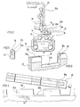
- FIG 3 shows an adjustment rail arrangement with a guide rail 10 and a slide rail 12 which is fixedly mounted on the vehicle floor during use.
- the two rails 10, 12 are as shown in FIG 3 becomes clear as an aluminum continuous casting profile which is connected to one another using bearing balls 14 in such a way that the guide rail 10 encloses the base part of the slide rail and supports or supports such that the slide rail 12 in the direction of the longitudinal axis A of the guide rail 10 movable or displaceable and reliably secured against lifting upwards.
- FIG. 1 and 4 each show the rails in their installation position, and with reference to this installation position the terms “above” and “below” and similar terms are used in the present description.)
- a locking lever 18 On one or upwardly projecting mounting flange 12a, with the upper angled end of which a seat is screwed or otherwise firmly connected, a locking lever 18 is articulated by means of a hinge pin 16, which is pressed downwards by means of a strong tension spring 20, ie in FIG. 1 and 2 is biased counterclockwise.
- a plurality of angled teeth 18a, in the exemplary embodiment 3, are formed on the locking lever 18.
- the locking lever is moved with the aid of an operating element (not shown) against the spring action of the tension spring 20 from the position shown in FIG. 1 pivoted clockwise to the position shown in FIG. 2, with its teeth 18a disengaged from the toothed splint 22.
- the slide rail 12 can be adjusted relative to the guide rail in the direction of the longitudinal axis A thereof, which in practice means that the seat (not shown) connected to the slide rail is moved forward or backward.
- the user has the impression that his seat is now in the correct position, he releases the control element, so that the locking lever 18 swings back in the direction of the toothed rail 22.
- plastic part 24 will normally have more or less rounded free edges.
- the plastic part 24 is, in the simplest case, only pushed onto the teeth 18a of the locking lever 18 and holds there due to a clamping force that can be predetermined by the shape and a suitable elasticity of the material.
- a clamping force that can be predetermined by the shape and a suitable elasticity of the material.
- better protection against loss or displacement of the plastic part 24 is achieved if the plastic part 24 is glued to the adjacent surfaces of the teeth or the adjacent base of the locking lever 18.
- locking means can be provided, which serve to secure the plastic part 24 on the locking lever 18 and the exact positioning of the plastic part 24.
- the plastic part 24 prevents any disruptive frictional contact between the guide surface 22c, the toothed rail 22 and the teeth 18a of the locking lever 18.
- the tooth flanks of the teeth 22a and 18a, apart from the front flank of the foremost tooth 18a, are not covered with a plastic layer, the exact positioning of the teeth 18a in the locking grooves 22b is maintained with narrow tolerances. 1 to 4 is achieved by a single, permanently connected to the locking lever 18 plastic part 24 in a simple and inexpensive manner that in the contact areas between the teeth 18a and the elements 22a, 22b of the rack 22 a low-friction sliding coating is present, which prevents unwanted abrasion on the aluminum guide rail 10.
- a web-like plastic part 26 to the toothed strip 22 in such a way that this strip-shaped plastic part protrudes upward above the end face of the teeth 22a or over the guide surface 22c.
- the plastic part 26 can be inserted into a groove in the toothed rail 22, as shown in FIG. 5, or in a fold provided on the side of the toothed rail 22, as shown in FIG. 6.
- the invention cannot be implemented only in the case of adjusting rail arrangements in which the locking lever can be pivoted about a horizontal axis running transversely to the direction of displacement, as in the exemplary embodiment 1 to 5 is the case, but also in such adjustment rail arrangements in which the locking lever is pivotable about an axis running parallel to the adjustment direction and has teeth which engage in closed openings of the toothed rail, the webs between the separate openings of the teeth correspond to the embodiment explained above.
- the teeth of the locking lever can be enclosed by the elements of a continuous plastic part in such a way that the metal material of the teeth does not come into direct contact with the side surface of the webs and causes abrasion there.
Landscapes
- Engineering & Computer Science (AREA)
- Aviation & Aerospace Engineering (AREA)
- Transportation (AREA)
- Mechanical Engineering (AREA)
- Seats For Vehicles (AREA)
Claims (9)
- Agencement de rails de réglage pour sièges de véhicules automobiles et analogues comportant un rail de guidage en aluminium (10) montable de manière fixe, muni d'une bande dentée (22) présentant des ouvertures d'enclenchement (22b) séparées les unes des autres par des éléments de dents (22a), une glissière (12) montable sur un siège et guidée par le rail de guidage, et des dispositifs d'arrêt (16, 18, 20) qui comportent un levier d'arrêt (18) en acier qui est fixé de manière pivotante sur la glissière (12) autour d'un axe de pivotement (pivot 16) qui s'étend transversalement à l'axe longitudinal (A) de la glissière (12), qui est soumis à une prétension par ressort dirigée contre la bande dentée et qui est muni sur son bord longitudinal tourné vers la bande dentée (22) de dents recourbées (18a) qui peuvent s'enclencher avec les ouvertures d'enclenchement (22b) de la bande dentée (22) et qui peuvent pénétrer dans les ouvertures d'enclenchement (22b) et en ressortir par pivotement du levier d'arrêt (18) autour d'un axe de pivotement pour enclencher ensemble de manière amovible la glissière (12) et le rail de guidage (10) dans des positions relatives axiales prédéterminées par le pas de la bande dentée (22) et par les dents (18a) du levier d'arrêt (18), caractérisé en ce que les éléments de dents (22a) de la bande dentée (22) et/ou moins la dent (18a) antérieure du levier d'arrêt (18) la plus proche de l'axe de pivotement sont munis dans un domaine de contact d'un revêtement de glissement (24) de faible frottement.
- Agencement de rails de réglage pour sièges de véhicules automobiles et analogues comportant un rail de guidage en aluminium montable de manière fixe, muni d'une bande dentée présentant des ouvertures d'enclenchement séparées les unes des autres par des éléments de dents, une glissière montable sur un siège et guidée par le rail de guidage, et des dispositifs d'arrêt qui comportent un levier d'arrêt en acier qui est fixé de manière pivotante sur la glissière autour d'un axe de pivotement (qui s'étend parallèlement à l'axe longitudinal de la glissière, qui est soumis à une prétension par ressort dirigée contre la bande dentée et qui est muni sur son bord longitudinal tourné vers la bande dentée de dents recourbées qui peuvent s'enclencher avec les ouvertures d'enclenchement du rail denté et qui peuvent pénétrer dans les ouvertures d'enclenchement et en ressortir par pivotement du levier d'arrêt pour enclencher ensemble de manière amovible la glissière et le rail de guidage dans des positions relatives axiales prédéterminées par le pas du rail denté et par les dents du levier d'arrêt, caractérisé en ce que les éléments de dents de la bande dentée et/ou les dents du levier d'arrêt sont munis dans un domaine de contact d'un revêtement de glissement de faible frottement.
- Agencement de rails de réglage selon la revendication 1 ou 2, caractérisé en ce que le revêtement de glissement consiste en matière plastique.
- Agencement de rails de réglage selon la revendication 3, caractérisé en ce que le revêtement de glissement comporte un capuchon en matière plastique.
- Agencement de rails de réglage selon la revendication 4, caractérisé en ce que le capuchon en matière plastique constitue un élément d'une pièce en matière plastique (24) qui comporte des revêtements de glissement pour plusieurs dents (18a).
- Agencement de rails de réglage selon la revendication 3, caractérisé en ce que le revêtement de glissement comporte des bandes en matière plastique (26) reliées à la bande dentée (22) et qui font saillie au-dessus de la surface de guidage (22c) de la bande dentée (22).
- Agencement de rails de réglage selon la revendication 3 ou 4, caractérisé en ce que le capuchon en matière plastique est relié à la pièce contiguë (18, 22) par emboîtement et/ou enclenchement et/ou collage.
- Agencement de rails de réglage selon la revendication 1 ou 2, caractérisé en ce que le revêtement de glissement est constitué par une couche de vernis.
- Agencement de rails de réglage selon la revendication 8, caractérisé en ce que la couche de vernis est obtenue par revêtement de poudre à l'aide d'un vernis de résine synthétique.
Applications Claiming Priority (2)
| Application Number | Priority Date | Filing Date | Title |
|---|---|---|---|
| DE3822452A DE3822452A1 (de) | 1988-07-02 | 1988-07-02 | Verstellschienenanordnung, insbesondere fuer pkw-sitze |
| DE3822452 | 1988-07-02 |
Publications (3)
| Publication Number | Publication Date |
|---|---|
| EP0349918A2 EP0349918A2 (fr) | 1990-01-10 |
| EP0349918A3 EP0349918A3 (en) | 1990-03-28 |
| EP0349918B1 true EP0349918B1 (fr) | 1993-01-20 |
Family
ID=6357832
Family Applications (1)
| Application Number | Title | Priority Date | Filing Date |
|---|---|---|---|
| EP89111952A Expired - Lifetime EP0349918B1 (fr) | 1988-07-02 | 1989-06-30 | Disposition de glissière, en particulier pour siège de voiture |
Country Status (2)
| Country | Link |
|---|---|
| EP (1) | EP0349918B1 (fr) |
| DE (2) | DE3822452A1 (fr) |
Families Citing this family (9)
| Publication number | Priority date | Publication date | Assignee | Title |
|---|---|---|---|---|
| DE4111544A1 (de) * | 1991-04-09 | 1992-10-15 | Worm Hans Gmbh Co Kg | Kugelfuehrung |
| IT1250346B (it) * | 1991-11-21 | 1995-04-07 | Elcat Spa | Dispositivo di regolazione longitudinale dei sedili di autoveicoli. |
| FR2730196B1 (fr) * | 1995-02-03 | 1997-04-04 | Faure Bertrand Equipements Sa | Glissiere verrouillable en position pour sieges de vehicules automobiles |
| DE19602250A1 (de) * | 1996-01-23 | 1997-07-24 | Teves Gmbh Alfred | Vorrichtung zur manuellen Längsverstellung eines Fahrzeugsitzes |
| EP0875187A3 (fr) * | 1997-04-24 | 2001-01-03 | Tchai Holding B.V. | Dispositif de présentation de produits |
| JP3295627B2 (ja) * | 1997-10-21 | 2002-06-24 | 富士機工株式会社 | シートスライド装置 |
| DE10206300B4 (de) | 2002-02-11 | 2005-12-22 | Keiper Gmbh & Co.Kg | Längseinsteller für einen Fahrzeugsitz |
| US7293752B2 (en) * | 2004-10-28 | 2007-11-13 | Lear Corporation | Positive engagement latch for a vehicle seat |
| US7581706B2 (en) | 2006-06-26 | 2009-09-01 | Lear Corporation | Shape memory alloy (SMA) system |
Family Cites Families (9)
| Publication number | Priority date | Publication date | Assignee | Title |
|---|---|---|---|---|
| DE1262688B (de) * | 1962-04-21 | 1968-03-07 | Metallgesellschaft Ag | Gleitwerkstoff |
| US3507472A (en) * | 1967-05-16 | 1970-04-21 | Howell Ind Inc | Seat mounting with telescopically arranged slide means |
| DE1906369A1 (de) * | 1969-02-08 | 1970-09-03 | Bbc Brown Boveri & Cie | Strombegrenzender Schalter mit Schlaganker |
| FR2044082A5 (fr) * | 1969-05-08 | 1971-02-19 | Peugeot & Renault | |
| DE2545763B2 (de) * | 1975-10-13 | 1979-06-21 | Ausscheidung in: 25 59 653 C Rob. Hammerstein GmbH, 5650 Solingen | Gleitschlenenfiihnuig für längs verschiebbare Fahrzeugsitze |
| DE2702576C2 (de) * | 1977-01-22 | 1982-11-11 | C. Rob. Hammerstein Gmbh, 5650 Solingen | Gleitschienenführung für Fahrzeugsitze |
| DE2729770C2 (de) * | 1977-07-01 | 1982-03-18 | C. Rob. Hammerstein Gmbh, 5650 Solingen | Feststellvorrichtung für Gleitschienenführungen eines Fahrzeugsitzes |
| IT7953821U1 (it) * | 1979-12-19 | 1981-06-19 | Gilardini Spa | Dispositivo di bloccaggio di una estremita' di una cintura di sicurezza per autoveicoli, rispetto ad una guida di scorrimento di un sedile. |
| JPH0615312B2 (ja) * | 1986-04-07 | 1994-03-02 | 株式会社大井製作所 | 自動車用シートスライド装置 |
-
1988
- 1988-07-02 DE DE3822452A patent/DE3822452A1/de not_active Withdrawn
-
1989
- 1989-06-30 EP EP89111952A patent/EP0349918B1/fr not_active Expired - Lifetime
- 1989-06-30 DE DE8989111952T patent/DE58903326D1/de not_active Expired - Fee Related
Also Published As
| Publication number | Publication date |
|---|---|
| DE3822452A1 (de) | 1990-01-04 |
| EP0349918A2 (fr) | 1990-01-10 |
| EP0349918A3 (en) | 1990-03-28 |
| DE58903326D1 (de) | 1993-03-04 |
Similar Documents
| Publication | Publication Date | Title |
|---|---|---|
| DE3049241C2 (fr) | ||
| DE69508742T2 (de) | Schubladenführung | |
| EP0345438A2 (fr) | Rideau écran on dispositif pour un coffre de véhicule automobile | |
| DE102009001308B4 (de) | Elektrisch höhenverstellbare Kopfstützvorrichtung eines Kraftfahrzeugsitzes | |
| DE3031610A1 (de) | Einstellvorrichtung zur stufenweisen sitzverschiebung fuer fahrzeuge | |
| DE2800908A1 (de) | Sitzverstellvorrichtung fuer fahrzeuge | |
| DE3242593A1 (de) | Hoehenverstellvorrichtung fuer einen kraftfahrzeug-sicherheitsgurt | |
| EP1854657B1 (fr) | Dispositif d'enjambement pour un évidement entre un siège de véhicule et le plancher d'un coffre à bagages | |
| DE2545763A1 (de) | Gleitschienenfuehrung fuer fahrzeugsitze | |
| DE19738202C2 (de) | Fahrzeugsitz mit einer höhenverstellbaren Kopfstütze | |
| DE2304031A1 (de) | Gleitvorrichtung | |
| DE2753307A1 (de) | Hoehen- und neigungsverstelleinrichtung fuer fahrzeugsitze | |
| EP1188603A1 (fr) | Surverrouillage pour dispositif de réglage longitudinal d'un siège de véhicule | |
| DE3401305A1 (de) | Vorrichtung zur stufenweisen regulierung der hoehe der verankerung von dreipunkt-sicherheitsgurten fuer fahrzeuge | |
| EP0349918A2 (fr) | Disposition de glissière, en particulier pour siège de voiture | |
| DE3149518A1 (de) | Sicherheitsgurtsystem fuer kraftfahrzeuge | |
| DE2820151A1 (de) | Gleitschiene zum vorwaerts- und rueckwaertsbewegen von fahrzeugsitzen, insbesondere kraftfahrzeugsitzen | |
| DE2601730A1 (de) | Anschnallgurtsystem | |
| EP0786371B1 (fr) | Dispositif pour le réglage manuel en position longitudinal d'un siège de véhicule | |
| DE102007014420A1 (de) | Vorrichtung zum Festlegen von Gegenständen | |
| DE3545974C1 (de) | Vorrichtung zum selbsttaetigen Festsetzen eines Betaetigungsgliedes einer Kraftfahrzeugfeststellbremse in dessen Betaetigungsstellung | |
| DE69012787T2 (de) | Lagebremse für Schiebetüren. | |
| DE3822453A1 (de) | Verstellschienenanordnung, insbesondere fuer pkw-sitze | |
| DE102013000741B4 (de) | Vorrichtung zur lösbaren Befestigung von Einbauteilen | |
| DE102004038392B4 (de) | Umlenkvorrichtung für einen Sicherheitsgurt |
Legal Events
| Date | Code | Title | Description |
|---|---|---|---|
| PUAI | Public reference made under article 153(3) epc to a published international application that has entered the european phase |
Free format text: ORIGINAL CODE: 0009012 |
|
| AK | Designated contracting states |
Kind code of ref document: A2 Designated state(s): DE ES FR GB |
|
| PUAL | Search report despatched |
Free format text: ORIGINAL CODE: 0009013 |
|
| AK | Designated contracting states |
Kind code of ref document: A3 Designated state(s): DE ES FR GB |
|
| 17P | Request for examination filed |
Effective date: 19900926 |
|
| 17Q | First examination report despatched |
Effective date: 19910906 |
|
| GRAA | (expected) grant |
Free format text: ORIGINAL CODE: 0009210 |
|
| AK | Designated contracting states |
Kind code of ref document: B1 Designated state(s): DE ES FR GB |
|
| PG25 | Lapsed in a contracting state [announced via postgrant information from national office to epo] |
Ref country code: GB Effective date: 19930120 Ref country code: FR Effective date: 19930120 Ref country code: ES Free format text: THE PATENT HAS BEEN ANNULLED BY A DECISION OF A NATIONAL AUTHORITY Effective date: 19930120 |
|
| REF | Corresponds to: |
Ref document number: 58903326 Country of ref document: DE Date of ref document: 19930304 |
|
| EN | Fr: translation not filed | ||
| GBV | Gb: ep patent (uk) treated as always having been void in accordance with gb section 77(7)/1977 [no translation filed] |
Effective date: 19930120 |
|
| PLBE | No opposition filed within time limit |
Free format text: ORIGINAL CODE: 0009261 |
|
| STAA | Information on the status of an ep patent application or granted ep patent |
Free format text: STATUS: NO OPPOSITION FILED WITHIN TIME LIMIT |
|
| 26N | No opposition filed | ||
| PGFP | Annual fee paid to national office [announced via postgrant information from national office to epo] |
Ref country code: DE Payment date: 19980710 Year of fee payment: 10 |
|
| PG25 | Lapsed in a contracting state [announced via postgrant information from national office to epo] |
Ref country code: DE Free format text: LAPSE BECAUSE OF NON-PAYMENT OF DUE FEES Effective date: 20000503 |