EP0349918B1 - Slide rail arrangement, especially for motor vehicle seats - Google Patents
Slide rail arrangement, especially for motor vehicle seats Download PDFInfo
- Publication number
- EP0349918B1 EP0349918B1 EP89111952A EP89111952A EP0349918B1 EP 0349918 B1 EP0349918 B1 EP 0349918B1 EP 89111952 A EP89111952 A EP 89111952A EP 89111952 A EP89111952 A EP 89111952A EP 0349918 B1 EP0349918 B1 EP 0349918B1
- Authority
- EP
- European Patent Office
- Prior art keywords
- rail
- teeth
- toothed
- slide
- border
- Prior art date
- Legal status (The legal status is an assumption and is not a legal conclusion. Google has not performed a legal analysis and makes no representation as to the accuracy of the status listed.)
- Expired - Lifetime
Links
- 239000011248 coating agent Substances 0.000 claims description 15
- 238000000576 coating method Methods 0.000 claims description 15
- 229910052782 aluminium Inorganic materials 0.000 claims description 11
- XAGFODPZIPBFFR-UHFFFAOYSA-N aluminium Chemical compound [Al] XAGFODPZIPBFFR-UHFFFAOYSA-N 0.000 claims description 11
- 239000002966 varnish Substances 0.000 claims description 7
- 229910000831 Steel Inorganic materials 0.000 claims description 3
- 239000010959 steel Substances 0.000 claims description 3
- 229920003002 synthetic resin Polymers 0.000 claims description 3
- 239000000057 synthetic resin Substances 0.000 claims description 3
- 239000000843 powder Substances 0.000 claims description 2
- 238000007767 slide coating Methods 0.000 claims 7
- 239000004411 aluminium Substances 0.000 claims 2
- 238000005299 abrasion Methods 0.000 description 7
- 239000000463 material Substances 0.000 description 7
- 230000009471 action Effects 0.000 description 2
- 230000008901 benefit Effects 0.000 description 2
- 238000011109 contamination Methods 0.000 description 2
- 238000006073 displacement reaction Methods 0.000 description 2
- 230000000694 effects Effects 0.000 description 2
- 238000009434 installation Methods 0.000 description 2
- 230000009191 jumping Effects 0.000 description 2
- 239000004922 lacquer Substances 0.000 description 2
- 238000004519 manufacturing process Methods 0.000 description 2
- 230000036316 preload Effects 0.000 description 2
- 230000001681 protective effect Effects 0.000 description 2
- 239000000853 adhesive Substances 0.000 description 1
- 230000001070 adhesive effect Effects 0.000 description 1
- 238000009749 continuous casting Methods 0.000 description 1
- 238000003618 dip coating Methods 0.000 description 1
- 239000000428 dust Substances 0.000 description 1
- 238000001125 extrusion Methods 0.000 description 1
- 230000002349 favourable effect Effects 0.000 description 1
- 239000000945 filler Substances 0.000 description 1
- 230000009969 flowable effect Effects 0.000 description 1
- 238000007654 immersion Methods 0.000 description 1
- 230000001771 impaired effect Effects 0.000 description 1
- 238000012423 maintenance Methods 0.000 description 1
- 230000007257 malfunction Effects 0.000 description 1
- 230000007246 mechanism Effects 0.000 description 1
- 239000007769 metal material Substances 0.000 description 1
- 239000003973 paint Substances 0.000 description 1
- 230000009467 reduction Effects 0.000 description 1
- 230000008439 repair process Effects 0.000 description 1
- 229920005989 resin Polymers 0.000 description 1
- 239000011347 resin Substances 0.000 description 1
- 230000000284 resting effect Effects 0.000 description 1
Images

Classifications
-
- B—PERFORMING OPERATIONS; TRANSPORTING
- B60—VEHICLES IN GENERAL
- B60N—SEATS SPECIALLY ADAPTED FOR VEHICLES; VEHICLE PASSENGER ACCOMMODATION NOT OTHERWISE PROVIDED FOR
- B60N2/00—Seats specially adapted for vehicles; Arrangement or mounting of seats in vehicles
- B60N2/02—Seats specially adapted for vehicles; Arrangement or mounting of seats in vehicles the seat or part thereof being movable, e.g. adjustable
- B60N2/04—Seats specially adapted for vehicles; Arrangement or mounting of seats in vehicles the seat or part thereof being movable, e.g. adjustable the whole seat being movable
- B60N2/06—Seats specially adapted for vehicles; Arrangement or mounting of seats in vehicles the seat or part thereof being movable, e.g. adjustable the whole seat being movable slidable
- B60N2/08—Seats specially adapted for vehicles; Arrangement or mounting of seats in vehicles the seat or part thereof being movable, e.g. adjustable the whole seat being movable slidable characterised by the locking device
- B60N2/0831—Movement of the latch
- B60N2/0837—Movement of the latch pivoting
- B60N2/085—Movement of the latch pivoting about a transversal axis
-
- B—PERFORMING OPERATIONS; TRANSPORTING
- B60—VEHICLES IN GENERAL
- B60N—SEATS SPECIALLY ADAPTED FOR VEHICLES; VEHICLE PASSENGER ACCOMMODATION NOT OTHERWISE PROVIDED FOR
- B60N2/00—Seats specially adapted for vehicles; Arrangement or mounting of seats in vehicles
- B60N2/02—Seats specially adapted for vehicles; Arrangement or mounting of seats in vehicles the seat or part thereof being movable, e.g. adjustable
- B60N2/04—Seats specially adapted for vehicles; Arrangement or mounting of seats in vehicles the seat or part thereof being movable, e.g. adjustable the whole seat being movable
- B60N2/06—Seats specially adapted for vehicles; Arrangement or mounting of seats in vehicles the seat or part thereof being movable, e.g. adjustable the whole seat being movable slidable
- B60N2/07—Slide construction
- B60N2/0702—Slide construction characterised by its cross-section
- B60N2/072—Complex cross-section, e.g. obtained by extrusion
-
- B—PERFORMING OPERATIONS; TRANSPORTING
- B60—VEHICLES IN GENERAL
- B60N—SEATS SPECIALLY ADAPTED FOR VEHICLES; VEHICLE PASSENGER ACCOMMODATION NOT OTHERWISE PROVIDED FOR
- B60N2/00—Seats specially adapted for vehicles; Arrangement or mounting of seats in vehicles
- B60N2/02—Seats specially adapted for vehicles; Arrangement or mounting of seats in vehicles the seat or part thereof being movable, e.g. adjustable
- B60N2/04—Seats specially adapted for vehicles; Arrangement or mounting of seats in vehicles the seat or part thereof being movable, e.g. adjustable the whole seat being movable
- B60N2/06—Seats specially adapted for vehicles; Arrangement or mounting of seats in vehicles the seat or part thereof being movable, e.g. adjustable the whole seat being movable slidable
- B60N2/08—Seats specially adapted for vehicles; Arrangement or mounting of seats in vehicles the seat or part thereof being movable, e.g. adjustable the whole seat being movable slidable characterised by the locking device
- B60N2/0812—Location of the latch
- B60N2/0825—Location of the latch outside the rail
Definitions
- the invention relates to an adjustment rail arrangement for motor vehicle seats and the like.
- a fixedly mountable aluminum guide rail with a toothed strip, with latching openings separated from one another by tooth elements, with a slide rail that can be mounted on a seat and guided through the guide rail, and with locking devices that comprise a locking lever made of steel.
- the state of the art for the variant with a swivel axis running transversely to the longitudinal axis of the slide rail results, for example, from DE-A-30 31 610, while the state of the art for the variant with a swivel axis running parallel to the longitudinal axis of the slide rail, for example, derives from the GB -A-2 188 543.
- the invention has for its object the disruptive abrasion on the aluminum guide rail in adjusting rail arrangements of the type under consideration or to reduce it to a minimum.
- toothed elements of the toothed rack and / or at least the foremost tooth of the locking lever which is closest to the pivot axis is provided with a low-friction sliding coating in a contact area.
- the object is achieved in that the tooth elements of the toothed rack and / or the teeth of the locking lever are provided with a low-friction sliding coating in a contact area.
- DE-A-27 02 576 describes an adjusting rail arrangement in which one rail is provided with a sliding shoe made of hard material in a contact area with which it rests on the other rail.
- the elements of the associated locking mechanism are designed in a conventional manner and without a low-friction sliding coating. This also essentially applies to the disclosure of DE-A-25 45 763, according to which plastic sliding bodies are arranged between the rails of a slide rail guide for vehicle seats without taking protective measures against wear with respect to the elements of the locking devices which are movable relative to one another.
- the particular advantage of the solution according to the invention is that a low-friction sliding coating on the tooth elements of the toothed rack or on at least one tooth of the locking lever can be attached inexpensively and with little technical effort in a variety of ways, and then the undesirable abrasion on the aluminum guide rail is effective prevented, but at least reduced to such an extent that, with normal use of the adjustment devices, the annoying black aluminum dust hardly occurs even over a longer period of time.
- a plastic cap can be placed on the teeth of the toothed strip and / or on the at least one tooth of the locking lever, it being possible for a continuous plastic part to be provided for several adjacent teeth.
- the plastic cap or the plastic part can be held on the teeth solely by the clamping action of an elastically deformable plastic material and / or by latching suitable latching elements on the plastic parts on the one hand, and the teeth or the toothed rack and the locking lever on the other.
- the plastic elements can also be glued to the teeth and / or adjacent parts of the toothed rack or the locking lever using a suitable adhesive.
- a particularly advantageous possibility also consists in using narrow plastic strips in the contact surfaces that come into frictional contact with one another, which can also be clamped again and / or locked and / or glued.
- a further advantageous possibility is to provide a varnish-like coating as a sliding coating for the tooth elements of the toothed rack and / or at least one tooth of the locking lever, which coating can be applied in any suitable manner, in particular in the form of a powder coating.
- Resin varnishes are particularly suitable as varnishes for the production of a low-friction sliding coating, which may contain a filler that improves the sliding effect.
- Such varnishes can be applied to the carefully degreased and cleaned teeth of the toothed rack and the locking lever by dip coating, whereby the synthetic resin material can be particularly securely fixed to the teeth by providing continuous bores in which the inflowing paint forms securing webs.
- the lacquer layer can also be secured by a corresponding surface structure of the teeth, in particular by tooth-shaped grooves running in the profile direction, the desired shape of the sliding coating on the free End faces of the teeth can be achieved according to the invention in that the teeth are held essentially vertically and with the free end faces downwards immediately after immersion, ie as long as the synthetic resin lacquer is still flowable.
- Suitable sliding materials or varnishes are described, for example, in DE-A-12 62 688 and in DE-Z: Industriean Attacher, No. 96 v. November 27, 1981, 103rd year, page 29.
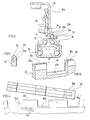
- FIG 3 shows an adjustment rail arrangement with a guide rail 10 and a slide rail 12 which is fixedly mounted on the vehicle floor during use.
- the two rails 10, 12 are as shown in FIG 3 becomes clear as an aluminum continuous casting profile which is connected to one another using bearing balls 14 in such a way that the guide rail 10 encloses the base part of the slide rail and supports or supports such that the slide rail 12 in the direction of the longitudinal axis A of the guide rail 10 movable or displaceable and reliably secured against lifting upwards.
- FIG. 1 and 4 each show the rails in their installation position, and with reference to this installation position the terms “above” and “below” and similar terms are used in the present description.)
- a locking lever 18 On one or upwardly projecting mounting flange 12a, with the upper angled end of which a seat is screwed or otherwise firmly connected, a locking lever 18 is articulated by means of a hinge pin 16, which is pressed downwards by means of a strong tension spring 20, ie in FIG. 1 and 2 is biased counterclockwise.
- a plurality of angled teeth 18a, in the exemplary embodiment 3, are formed on the locking lever 18.
- the locking lever is moved with the aid of an operating element (not shown) against the spring action of the tension spring 20 from the position shown in FIG. 1 pivoted clockwise to the position shown in FIG. 2, with its teeth 18a disengaged from the toothed splint 22.
- the slide rail 12 can be adjusted relative to the guide rail in the direction of the longitudinal axis A thereof, which in practice means that the seat (not shown) connected to the slide rail is moved forward or backward.
- the user has the impression that his seat is now in the correct position, he releases the control element, so that the locking lever 18 swings back in the direction of the toothed rail 22.
- plastic part 24 will normally have more or less rounded free edges.
- the plastic part 24 is, in the simplest case, only pushed onto the teeth 18a of the locking lever 18 and holds there due to a clamping force that can be predetermined by the shape and a suitable elasticity of the material.
- a clamping force that can be predetermined by the shape and a suitable elasticity of the material.
- better protection against loss or displacement of the plastic part 24 is achieved if the plastic part 24 is glued to the adjacent surfaces of the teeth or the adjacent base of the locking lever 18.
- locking means can be provided, which serve to secure the plastic part 24 on the locking lever 18 and the exact positioning of the plastic part 24.
- the plastic part 24 prevents any disruptive frictional contact between the guide surface 22c, the toothed rail 22 and the teeth 18a of the locking lever 18.
- the tooth flanks of the teeth 22a and 18a, apart from the front flank of the foremost tooth 18a, are not covered with a plastic layer, the exact positioning of the teeth 18a in the locking grooves 22b is maintained with narrow tolerances. 1 to 4 is achieved by a single, permanently connected to the locking lever 18 plastic part 24 in a simple and inexpensive manner that in the contact areas between the teeth 18a and the elements 22a, 22b of the rack 22 a low-friction sliding coating is present, which prevents unwanted abrasion on the aluminum guide rail 10.
- a web-like plastic part 26 to the toothed strip 22 in such a way that this strip-shaped plastic part protrudes upward above the end face of the teeth 22a or over the guide surface 22c.
- the plastic part 26 can be inserted into a groove in the toothed rail 22, as shown in FIG. 5, or in a fold provided on the side of the toothed rail 22, as shown in FIG. 6.
- the invention cannot be implemented only in the case of adjusting rail arrangements in which the locking lever can be pivoted about a horizontal axis running transversely to the direction of displacement, as in the exemplary embodiment 1 to 5 is the case, but also in such adjustment rail arrangements in which the locking lever is pivotable about an axis running parallel to the adjustment direction and has teeth which engage in closed openings of the toothed rail, the webs between the separate openings of the teeth correspond to the embodiment explained above.
- the teeth of the locking lever can be enclosed by the elements of a continuous plastic part in such a way that the metal material of the teeth does not come into direct contact with the side surface of the webs and causes abrasion there.
Landscapes
- Engineering & Computer Science (AREA)
- Aviation & Aerospace Engineering (AREA)
- Transportation (AREA)
- Mechanical Engineering (AREA)
- Seats For Vehicles (AREA)
Description
Die Erfindung betrifft eine Verstellschienenanordnung für Kraftfahrzeugsitze und dgl. mit einer ortsfest montierbaren Aluminiumführungsschiene, mit einer Zahnleiste, mit durch Zahnelemente voneinander getrennten Rastöffnungen mit einer an einem Sitz montierbaren, durch die Führungsschiene geführten Gleitschiene und mit Arretiereinrichtungen, welche einen aus Stahl bestehenden Arretierhebel umfassen, der um eine quer zur Längsache oder um eine parallel zur Längsachse der Gleitschiene verlaufende Schwenkachse schwenkbar an der Gleitschiene befestigt ist, unter einer gegen die Zahnleiste gerichteten Federvorspannung steht und an seiner der Zahnleiste zugewandten Längskante mit abgewinkelten Zähnen versehen ist, die mit den Rastöffnungen der Zahnleiste verrastbar und durch Schwenken des Arretierhebels um eine Schwenkachse aus den Rastöffnungen heraus- und in diese hineinbewegbar sind, um Gleitschiene und Führungsschiene in durch die Zahnteilung der Zahnleiste und der Zähne des Arretierhebels vorgegebenen axialen Relativstellungen lösbar miteinander zu verrasten.The invention relates to an adjustment rail arrangement for motor vehicle seats and the like. With a fixedly mountable aluminum guide rail, with a toothed strip, with latching openings separated from one another by tooth elements, with a slide rail that can be mounted on a seat and guided through the guide rail, and with locking devices that comprise a locking lever made of steel. which is pivotably attached to the slide rail about a pivot axis running transversely to the longitudinal axis or about a parallel axis to the longitudinal axis of the slide rail, is under a spring preload directed against the toothed strip and is provided with angled teeth on its longitudinal edge facing the toothed strip, which has the latching openings of the toothed strip can be locked and moved by pivoting the locking lever about a pivot axis out of the latching openings and into these to slide rail and guide rail in by the tooth pitch of the rack and the teeth of the Locking lever releasably lock predetermined axial relative positions together.
Dabei ergibt sich der Stand der Technik für die Variante mit quer zur Längsachse der Gleitschiene verlaufender Schwenkachse beispielsweise aus der DE-A-30 31 610, während sich der Stand der Technik für die Variante mit parallel zur Längsachse der Gleitschiene verlaufender Schwenkachse beispielsweise aus der GB-A-2 188 543 ergibt.The state of the art for the variant with a swivel axis running transversely to the longitudinal axis of the slide rail results, for example, from DE-A-30 31 610, while the state of the art for the variant with a swivel axis running parallel to the longitudinal axis of the slide rail, for example, derives from the GB -A-2 188 543.
Allgemein sind derartige Verstellschienenanordnungen weit verbreitet und gestatten es dem Fahrer eines Kraftfahrzeugs oder dgl., den Fahrersitz bezüglich der Bedienelemente des Fahrzeugs in die für ihn günstigste Position zu bringen. In entsprechender Weise dienen die Sitzverstellungen bei Beifahrern und Passagieren dazu, die Einstellung einer möglichst bequemen Sitzhaltung zu ermöglichen. In allen Fällen muß dabei trotz der Verstellbarkeit der Sitze gewährleistet sein, daß diese auch bei extremen Belastungen, beispielsweise beim Frontalaufprall eines Kraftfahrzeugs, sicher in der eingestellten Lage gehalten werden, was bei den Verstellschienenanordnungen der betrachteten Art auch zuverlässig gewährleistet ist, da die Anzahl der kammartig ineinander greifenden Zähne der Zahnleiste einerseits und des Arretierhebels andererseits, die Materialstärke der Zähne und die am Arretierhebel wirksame Federvorspannung ein Herausspringen der Zähne des Arretierhebels aus der Zahnung der Zahnleiste zuverlässig verhindern.In general, such adjustment rail arrangements are widespread and allow the driver of a motor vehicle or the like to place the driver's seat in the position most favorable to him with regard to the operating elements of the vehicle bring to. In a corresponding manner, the seat adjusters for passengers and passengers serve to enable the most comfortable sitting position possible. In all cases, despite the adjustability of the seats, it must be ensured that these are held securely in the set position even under extreme loads, for example in the event of a frontal impact of a motor vehicle, which is also reliably ensured in the case of the adjustment rail arrangements of the type under consideration, since the number of comb-like interdigitated teeth of the toothed rack on the one hand and the locking lever on the other hand, the material thickness of the teeth and the spring preload effective on the locking lever reliably prevent the teeth of the locking lever from jumping out of the teeth of the toothed rack.
Bei der Verwendung von Aluminium-Führungsschienen, deren Einsatz wegen ihres geringen Gewichts erwünscht ist und die mit hoher Präzision durch Strangpressen hergestellt werden können, hat es sich als nachteilig erwiesen, daß beim Verstellen des Sitzes durch den Kontakt zwischen dem bezüglich der Schwenkachse des Arretierhebels vordersten Zahn desselben und dem freien äußeren Rand der Zahnleiste der Aluminium-Führungsschiene mit der Zeit ein beträchtlicher Abrieb an der Zahnleiste entsteht, der einen schmierigen schwarzen Belag bildet, welcher bei Wartungs- und Reparaturarbeiten nur schlecht zu entfernen ist und die Gefahr einer Verschmutzung der Bekleidung und der Hände der Fahrzeugbenutzer mit sich bringt, wenn beispielsweise ein unter einen Sitz gefallener Gegenstand "im Dunkeln" tastend gesucht wird.When using aluminum guide rails, the use of which is desired because of their low weight and which can be produced with high precision by extrusion, it has proven to be disadvantageous that when the seat is adjusted by the contact between the foremost with respect to the pivot axis of the locking lever Tooth of the same and the free outer edge of the toothed strip of the aluminum guide rail over time creates a considerable abrasion on the toothed strip, which forms a greasy black coating, which is difficult to remove during maintenance and repair work and the risk of contamination of the clothing and which brings the hands of the vehicle user with it, for example when an object falling under a seat is groping "in the dark".
Der Erfindung liegt die Aufgabe zugrunde, den störenden Abrieb an der Aluminium-Führungsschiene bei Verstellschienenanordnungen der betrachteten Art zu verhindern oder doch auf ein Minimum zu reduzieren.The invention has for its object the disruptive abrasion on the aluminum guide rail in adjusting rail arrangements of the type under consideration or to reduce it to a minimum.
Diese Aufgabe wird gemäß einer ersten Variante der Erfindung dadurch gelöst, daß die Zahnelemente der Zahnleiste und/oder mindestens der der Schwenkachse am nächsten benachbarte vorderste Zahn des Arretierhebels in einem Kontaktbereich mit einem reibungsarmen Gleitbelag versehen ist.This object is achieved according to a first variant of the invention in that the toothed elements of the toothed rack and / or at least the foremost tooth of the locking lever which is closest to the pivot axis is provided with a low-friction sliding coating in a contact area.
Gemäß einer zweiten Variante der Erfindung wird die gestellte Aufgabe dadurch gelöst, daß die Zahnelemente der Zahnleiste und/oder die Zähne des Arretierhebels in einem Kontaktbereich mit einem reibungsarmen Gleitbelag versehen sind.According to a second variant of the invention, the object is achieved in that the tooth elements of the toothed rack and / or the teeth of the locking lever are provided with a low-friction sliding coating in a contact area.
Bei Verstellschienenanordnungen für Kraftfahrzeugsitze und dergleichen ist zwar die Verwendung von Gleitelementen unterschiedlicher Art bereits bekannt; die vorbekannten Lösungen befassen sich jedoch sämtlich mit der Verringerung der Reibung zwischen den relativ zueinander verschieblichen Schienen, ohne zu berücksichtigen, daß auch bei der Betätigung der Arretiereinrichtungen ein Reibkontakt zwischen relativ zueinander beweglichen Teilen erfolgt und daß dieser Reibkontakt Verschleißerscheinungen zur Folge hat, die nicht nur zu einer Verschmutzung der Verstellschienenanordnung führen, sondern nach längerer Gebrauchszeit auch Funktionsstörungen zur Folge haben können, insbesondere wenn Abrieb von den relativ zueinander beweglichen Teilen zwischen die Schienen der Verstellschienenanordnung gerät und deren freie Verstellbarkeit relativ zueinander beeinträchtigt. So ist beispielsweise in der DE-A-27 02 576 eine Verstellschienenanordnung beschrieben, bei der die eine Schiene in einem Kontaktbereich, mit dem sie an der anderen Schiene anliegt, mit einem Gleitschuh aus hartem Material versehen ist. Andererseits sind die Elemente des zugehörigen Arretiermechanismus in konventioneller Weise und ohne einen reibungsarmen Gleitbelag ausgebildet. Dies gilt im wesentlichen auch für die Offenbarung der DE-A-25 45 763, gemäß welcher zwischen den Schienen einer Gleitschienenführung für Fahrzeugsitze Kunststoffgleitkörper angeordnet werden, ohne daß bezüglich der relativ zueinander beweglichen Elemente der Arretiereinrichtungen Schutzmaßnahmen gegen einen Verschleiß getroffen würden. Auch bei einer durch das DE-GM 19 06 369 bekannten Sitzführung für Kraftfahrzeugsitze dienen streifenförmige Gleitelemente aus Kunststoff lediglich der Verbesserung der Führung der Schienen sowie der störungsfreien Anordnung von Schraubenköpfen, ohne daß hinsichtlich der Arretiereinrichtungen Schutzmaßnahmen gegen einen erhöhten Verschleiß getroffen würden. In entsprechender Weise befaßt sich auch das DE-GM-70 16 740 lediglich mit einer vorteilhaften gleitverschieblichen Führung der Schienen, insbesondere der Führungsschienen für eine Schublade, wobei die vorgeschlagenen Gleitelemente jedoch aufgrund des Vorhandenseins eines weichen Gleitführungselementes nicht für eine Sitzschienenführung geeignet wären und wobei überdies auch keine Arretiereinrichtungen vorgesehen sind.In the case of adjusting rail arrangements for motor vehicle seats and the like, the use of different types of sliding elements is already known; the known solutions, however, all deal with the reduction of the friction between the rails which are displaceable relative to one another, without taking into account that, even when the locking devices are actuated, there is frictional contact between parts which are movable relative to one another and that this frictional contact results in signs of wear which are not only lead to contamination of the adjustment rail arrangement, but can also result in malfunctions after a long period of use, in particular if abrasion from the parts which are movable relative to one another gets between the rails of the adjustment rail arrangement and their free adjustability relative to one another is impaired. For example, DE-A-27 02 576 describes an adjusting rail arrangement in which one rail is provided with a sliding shoe made of hard material in a contact area with which it rests on the other rail. On the other hand, the elements of the associated locking mechanism are designed in a conventional manner and without a low-friction sliding coating. This also essentially applies to the disclosure of DE-A-25 45 763, according to which plastic sliding bodies are arranged between the rails of a slide rail guide for vehicle seats without taking protective measures against wear with respect to the elements of the locking devices which are movable relative to one another. Even with a seat guide for motor vehicle seats known from DE-GM 19 06 369, strip-shaped sliding elements made of plastic only serve to improve the guidance of the rails and the trouble-free arrangement of screw heads, without protective measures being taken against increased wear with regard to the locking devices. In a corresponding manner, DE-GM-70 16 740 only deals with an advantageous sliding guide of the rails, in particular the guide rails for a drawer, the proposed sliding elements, however, would not be suitable for a seat rail guide due to the presence of a soft sliding guide element, and moreover also no locking devices are provided.
Der besondere Vorteil der erfindungsgemäßen Lösung besteht dagegen darin, daß ein reibungsarmer Gleitbelag an den Zahnelementen der Zahnleiste bzw. an mindestens einem Zahn des Arretierhebels in vielfältiger Weise preiswert und mit geringem technischen Aufwand angebracht werden kann und dann den unerwünschten Abrieb an der Aluminium-Führungsschiene wirksam verhindert, zumindest aber soweit verringert, daß bei normaler Benutzung der Verstelleinrichtungen auch über einen längeren Zeitraum hinweg kaum noch der störende schwarze Aluminiumstaub auftritt.The particular advantage of the solution according to the invention, however, is that a low-friction sliding coating on the tooth elements of the toothed rack or on at least one tooth of the locking lever can be attached inexpensively and with little technical effort in a variety of ways, and then the undesirable abrasion on the aluminum guide rail is effective prevented, but at least reduced to such an extent that, with normal use of the adjustment devices, the annoying black aluminum dust hardly occurs even over a longer period of time.
Was die vorteilhaften Möglichkeiten für die Anbringung eines Gleitbelags an den bei einem Verstellkontakt in Reibkontakt miteinander gelangenden Teilen der Verstellschienenanordnung anbelangt, so ergeben sich in vorteilhafter Ausgestaltung der Erfindung insbesondere folgende preislich und fertigungstechnisch vorteilhafte Möglichkeiten:
Auf die Zähne der Zahnleiste und/oder auf den mindestens einen Zahn des Arretierhebels kann jeweils eine Kunststoffkappe aufgesetzt werden, wobei ggf. für mehrere benachbarte Zähne ein durchgehendes Kunststoffteil vorgesehen werden kann. Die Kunststoffkappe bzw. das Kunststoffteil kann dabei an den Zähnen allein durch die Klemmwirkung eines elastisch verformbaren Kunststoffmaterials gehalten werden und/oder durch Verrasten geeigneter Rastelemente an den Kunststoffteilen einerseits, und den Zähnen bzw. der Zahnleiste und dem Arretierhebel andererseits. Zusätzlich oder stattdessen können die Kunststoffelemente auch an den Zähnen und/oder benachbarten Teilen der Zahnleiste bzw. des Arretierhebels unter Verwendung eines geeigneten Klebers festgeklebt werden.As far as the advantageous possibilities for the application of a sliding coating to the parts of the adjusting rail arrangement which come into frictional contact with one another in the case of an adjusting contact, in an advantageous embodiment of the invention there are in particular the following options which are advantageous in terms of price and production technology:
A plastic cap can be placed on the teeth of the toothed strip and / or on the at least one tooth of the locking lever, it being possible for a continuous plastic part to be provided for several adjacent teeth. The plastic cap or the plastic part can be held on the teeth solely by the clamping action of an elastically deformable plastic material and / or by latching suitable latching elements on the plastic parts on the one hand, and the teeth or the toothed rack and the locking lever on the other. Additionally or instead, the plastic elements can also be glued to the teeth and / or adjacent parts of the toothed rack or the locking lever using a suitable adhesive.
Eine besonders vorteilhafte Möglichkeit besteht ferner darin, in die in Reibkontakt miteinander gelangenden Kontaktflächen schmale Kunststoffleisten einzusetzen, die ebenfalls wieder festgeklemmt und/oder verrastet und/oder verklebt sein können.A particularly advantageous possibility also consists in using narrow plastic strips in the contact surfaces that come into frictional contact with one another, which can also be clamped again and / or locked and / or glued.
Eine weitere vorteilhafte Möglichkeit besteht darin, als Gleitbelag für die Zahnelemente der Zahnleiste und/oder mindestens einen Zahn des Arretierhebels eine lackartige Beschichtung vorzusehen, die in beliebiger, geeigneter Weise aufgebracht werden kann, insbesondere in Form einer Pulverbeschichtung.A further advantageous possibility is to provide a varnish-like coating as a sliding coating for the tooth elements of the toothed rack and / or at least one tooth of the locking lever, which coating can be applied in any suitable manner, in particular in the form of a powder coating.
Als Lacke für die Herstellung eines reibungsarmen Gleitbelags eignen sich dabei besonders Kunstharzlacke, die ggf. einen die Gleitwirkung verbessernden Füller enthalten können. Derartige Lacke können auf die sorgfältig entfetteten und gereinigten Zähne der Zahnleiste und des Arretierhebels durch Tauchlackierung aufgebracht werden, wobei das Kunstharzmaterial dadurch besonders sicher an den Zähnen festgelegt werden kann, daß in diesen durchgehende Bohrungen vorgesehen werden, in denen der einfließende Lack Sicherungsstege bildet. Die Sicherung der Lackschicht kann ferner durch eine entsprechende Oberflächenstruktur der Zähne, insbesondere durch in Profilrichtung verlaufende zahnförmige Riefen erreicht werden, wobei die gewünschte Form des Gleitbelags an den freien Stirnflächen der Zähne erfindungsgemäß dadurch erreicht werden kann, daß die Zähne unmittelbar nach dem Tauchen, d.h. solange der Kunstharzlack noch fließfähig ist, im wesentlichen senkrecht und mit den freien Stirnflächen nach unten gehaltert werden. Geeignete Gleitwerkstoffe bzw. -lacke sind beispielsweise in der DE-A-12 62 688 sowie in der DE-Z: Industrieanzeiger, Nr. 96 v. 27.11.1981, 103. Jg., Seite 29, beschrieben.Resin varnishes are particularly suitable as varnishes for the production of a low-friction sliding coating, which may contain a filler that improves the sliding effect. Such varnishes can be applied to the carefully degreased and cleaned teeth of the toothed rack and the locking lever by dip coating, whereby the synthetic resin material can be particularly securely fixed to the teeth by providing continuous bores in which the inflowing paint forms securing webs. The lacquer layer can also be secured by a corresponding surface structure of the teeth, in particular by tooth-shaped grooves running in the profile direction, the desired shape of the sliding coating on the free End faces of the teeth can be achieved according to the invention in that the teeth are held essentially vertically and with the free end faces downwards immediately after immersion, ie as long as the synthetic resin lacquer is still flowable. Suitable sliding materials or varnishes are described, for example, in DE-A-12 62 688 and in DE-Z: Industrieanzeiger, No. 96 v. November 27, 1981, 103rd year, page 29.
Weitere Einzelheiten und Vorteile der Erfindung werden nachstehend anhand von Zeichnungen noch näher erläutert. Es zeigen:
- Fig. 1
- eine Seitenansicht einer bevorzugten Ausführungsform einer Verstellschienenanordnung gemäß der Erfindung im verrasteten Zustand;
- Fig. 2
- eine Seitenansicht der Verstellschienenanordnung gemäß Fig. 1 im ausgerasteten Zustand;
- Fig. 3
- einen Querschnitt durch die Verstellschienenanordnung gemäß Fig. 1 längs der Linie III-III in dieser Figur;
- Fig. 4
- eine vergrößerte Teil-Seitenansicht der Anordnung gemäß Fig. 2 und
- Fig. 5 und 6
- schematische Querschnitte zweier bevorzugter Ausführungsformen der Zahnschiene für eine Verstellschienenanordnung gemäß Fig. 1 bis 4, wobei jedoch auf das dort vorgesehene reibungsarme Kunststoffteil verzichtet werden kann.
- Fig. 1
- a side view of a preferred embodiment of an adjustment rail assembly according to the invention in the locked state;
- Fig. 2
- a side view of the adjustment rail assembly of FIG 1 in the disengaged state.
- Fig. 3
- a cross section through the adjustment rail assembly of Figure 1 along the line III-III in this figure.
- Fig. 4
- an enlarged partial side view of the arrangement of FIG. 2 and
- 5 and 6
- schematic cross sections of two preferred embodiments of the toothed rail for an adjusting rail arrangement according to FIGS. 1 to 4, but the low-friction plastic part provided there can be dispensed with.
Im einzelnen zeigt Fig. 1, in der einige Teile im Schnitt dargestellt und andere weggebrochen sind, eine Verstellschienenanordnung mit einer im Gebrauch ortsfest am Fahrzeugboden montierten Führungsschiene 10 und einer Gleitschiene 12. Beim Ausführungsbeispiel sind die beiden Schienen 10, 12, wie dies aus Fig. 3 deutlich wird, als Aluminium-Stranggußprofile ausgebildet, die unter Verwendung von Lagerkugeln 14 derart miteinander verbunden sind, daß die Führungsschiene 10 den Basisteil der Gleitschiene umschließt und derart lagert bzw. haltert, daß die Gleitschiene 12 in Richtung der Längsachse A der Führungsschiene 10 verfahrbar bzw. verschiebbar und gegen ein Abheben nach oben zuverlässig gesichert ist. (Die Zeichnungsfiguren 1 bis 4 zeigen die Schienen jeweils in ihrer Einbaulage, und unter Bezugnahme auf diese Einbaulage wird in der vorliegenden Beschreibung mit den Begriffen "oben" und "unten" und ähnlichen Bezeichnungen gearbeitet.)
An einem oder nach oben abstehenden Befestigungsflansch 12a, mit dessen oberem abgewinkelten Ende ein Sitz verschraubt oder in anderer Weise fest verbunden wird, ist mit Hilfe eines Gelenkzapfens 16 ein Arretierhebel 18 angelenkt, der mittels einer kräftigen Spannfeder 20 nach unten, d.h. in Fig. 1 und 2 im Gegenuhrzeigersinn, vorgespannt ist. An dem Arretierhebel 18 sind mehrere, beim Ausführungsbeispiel 3, abgewinkelte Zähne 18a angeformt. Bei verrasteter Verstellschienenanordnung greifen diese Zähne 18a in nach außen bzw. nach oben offene Rastnuten 22b ein, die zwischen den Zähnen 22a einer Zahnleiste 22 der Führungsschiene 10 vorgesehen sind. Die Zahnleiste 22 steht dabei nach oben frei über die restlichen Teile der Führungsschiene 10 vor und verläuft parallel zu dem Befestigungsflansch 12a der Gleitschiene 12. Der verrastete Zustand zwischen den Zähnen 10a des Arretierhebels 18 und den Rastnuten 22b bzw. den Zähnen 22a der Zahnschiene ist in Fig. 1 gezeigt und gewährleistet eine sichere Verriegelung der beiden Schienen 10, 12 gegen eine axiale Längsverstellung und damit eine zuverlässige Fixierung der Lage eines an dem Befestigungsflansch 12a befestigten Sitzes bezüglich des Fahrzeugbodens, mit dem die Führungsschiene 10 fest verbunden ist.1, in which some parts are shown in section and others have broken away, shows an adjustment rail arrangement with a
On one or upwardly projecting
Wenn, ausgehend von der Position gemäß Fig. 1, die axiale Relativlage der beiden Schienen 10 und 12 geändert werden soll, dann wird der Arretierhebel mit Hilfe eines Bedienelements (nicht gezeigt) entgegen der Federwirkung der Spannfeder 20 aus der in Fig. 1 gezeigten Stellung im Uhrzeigersinn in die in Fig. 2 gezeigte Stellung geschwenkt, wobei seine Zähne 18a außer Eingriff mit der Zahnschiene 22 gebracht werden. Nunmehr kann die Gleitschiene 12 relativ zu der Führungsschiene in Richtung der Längsachse A derselben verstellt werden, was in der Praxis bedeutet, daß der mit der Gleitschiene verbundene Sitz (nicht gezeigt) nach vorn oder hinten verstellt wird. Sobald der Benutzer dabei den Eindruck hat, daß sich sein Sitz nunmehr in der richtigen Position befindet, gibt er das Bedienelement frei, so daß der Arretierhebel 18 wieder in Richtung auf die Zahnschiene 22 zurückschwenkt. Da die Zähne 18a und 22a mit engen Toleranzen ineinander greifen, um während der Fahrt, insbesondere aber bei einem Aufprall des Fahrzeugs, jede Relativbewegung zwischen Fahrzeugboden und Sitz zu verhindern, hat dieses Zurückschwenken des Arretierhebels 18 regelmäßig zur Folge, daß der vorderste Zahn 18a des Arretierhebels 18, welcher dem Gelenkzapfen 16 am nächsten benachbart ist, mit seiner Vorderkante 18a′ auf die durch das freie Ende der Zähne 22a der Zahnschiene 22 gebildete, durch die Rastnuten 22b unterbrochene Führungsfläche 22c der Zahnschiene auftrifft. Wenn nunmehr der Sitz nach dem Loslassen des Bedienelements noch geringfügig nach vorn oder hinten verstellt wird, um die Arretierung zum Einrasten zu bringen, dann erzeugt die Vorderkante 18a des auf der Führungsfläche 22c aufliegenden vorderen Zahns 18a an der Führungsfläche normalerweise einen gewissen störenden Abrieb, da die volle Kraft der Spannfeder 20 zwischen der normalerweise scharfen Vorderkante 18a und der quer zur Bewegungsrichtung schmalen Führungsfläche 22c der aus Aluminium bestehenden Führungsschiene 10 wirksam wird.If, starting from the position according to FIG. 1, the axial relative position of the two
Dieses Problem der vorbekannten Verstellschienenanordnung wird erfindungsgemäß dadurch vermieden bzw. erheblich verringert, daß auf die Zahnung des Arretierhebels 18 ein Kunststoffteil 24 aufgesetzt wird, welches, wie dies speziell aus Fig. 4 deutlich wird, den vordersten Zahn 18a als U-förmiger Gleitbelag umschließt und bei den übrigen Zähnen 18 jeweils die Vorderseite und die Rückseite bzw. die Oberseite und die Unterseite derselben bedeckt. Dabei versteht es sich, daß die Wandstärke des Kunststoffteils normalerweise relativ gering ist und zumindest im Bereich der Zähne nur etwa 0,2 bis 0,4 mm beträgt, so daß auch bei einer Verformung des Kunststoffmaterials keine Gefahr für ein Herausspringen der Zähne 18a des Arretierhebels 18 aus den Rastnuten 22b der Zahnleiste 22 besteht. Insofern ist die Darstellung gemäß Fig. 4 als schematische Darstellung zu werten, in der die Wandstärke des Kunststoffteils 24 übertrieben dargestellt ist.This problem of the known adjustment rail arrangement is avoided or considerably reduced according to the invention in that a
Ferner versteht es sich, daß das Kunststoffteil 24 normalerweise mehr oder weniger stark abgerundete freie Kanten aufweisen wird.Furthermore, it is understood that the
Das Kunststoffteil 24 wird, wie eingangs erläutert, im einfachsten Fall nur auf die Zähne 18a des Arretierhebels 18 aufgesteckt und hält sich dort aufgrund einer durch die Formgebung und eine geeignete Elastizität des Materials vorgebbaren Klemmkraft. Ein besserer Schutz gegen einen Verlust bzw. eine Verschiebung des Kunststoffteils 24 wird jedoch dann erreicht, wenn das Kunststoffteil 24 mit den angrenzenden Flächen der Zähne bzw. der benachbarten Basis des Arretierhebels 18 verklebt wird. Zusätzlich können Rastmittel vorgesehen sein, die der Sicherung des Kunststoffteils 24 an dem Arretierhebel 18 sowie der exakten Positionierung des Kunststoffteils 24 dienen.In the simplest case, the
Aus der Betrachtung der Zeichnungen wird in Verbindung mit der eingangs gegegebenen Erläuterung unmittelbar deutlich, daß durch das Kunststoffteil 24 jeder störende Reibkontakt zwischen der Führungsfläche 22c, der Zahnschiene 22 und den Zähnen 18a des Arretierhebels 18 verhindert wird. Da andererseits die Zahnflanken der Zähne 22a und 18a, abgesehen von der Vorderflanke des vordersten Zahns 18a, nicht mit einer Kunststoffschicht überdeckt sind, wird außerdem die exakte Positionierung der Zähne 18a in den Rastnuten 22b mit engen Toleranzen aufrechterhalten. Bei dem Ausführungsbeispiel gemäß Fig. 1 bis 4 wird also durch ein einziges, dauerhaft mit dem Arretierhebel 18 verbundenes Kunststoffteil 24 auf einfache und preiswerte Weise erreicht, daß in den Kontaktbereichen zwischen den Zähnen 18a und den Elementen 22a, 22b der Zahnleiste 22 ein reibungsarmer Gleitbelag vorhanden ist, der einen unerwünschten Abrieb an der Aluminium-Führungsschiene 10 verhindert.From the consideration of the drawings in connection with the explanation given at the outset it is immediately clear that the
Wie aus der vorstehenden Beschreibung deutlich wird, kann im wesentlichen derselbe Effekt wie mit dem mit dem Arretierhebel 18 verbundenen Kunststoffteil 24 auch dadurch erzielt werden, daß man ein entsprechendes Kunststoffteil auf die Zähne 22a der Zahnschiene 22 aufsetzt, wobei ein entsprechendes Kunststoffteil ggf. auch zusätzlich zu dem Kunststoffteil 24 vorgesehen sein kann.As is clear from the above description, essentially the same effect as with the
Weiterhin besteht die Möglichkeit, mit der Zahnleiste 22 ein stegartiges Kunststoffteil 26 derart zu verbinden, daß dieses leistenförmige Kunststoffteil nach oben über die Stirnfläche der Zähne 22a bzw. über die Führungsfläche 22c vorsteht. Dabei kann das Kunststoffteil 26 in eine Nut der Zahnschiene 22 eingesetzt sein, wie dies in Fig. 5 gezeigt ist, oder in einen seitlich an der Zahnschiene 22 vorgesehenen Falz, wie dies in Fig. 6 gezeigt ist.Furthermore, there is the possibility of connecting a web-like
Weiterhin soll noch - ohne daß diese Variante in den Zeichnungen eigens dargestellt wird - darauf hingewiesen werden, daß die Erfindung nicht nur bei Verstellschienenanordnungen realisiert werden kann, bei denen der Arretierhebel um eine quer zur Verschieberichtung verlaufende horizontale Achse schwenkbar ist, wie dies bei dem Ausführungsbeispiel gemäß Fig. 1 bis 5 der Fall ist, sondern auch bei solchen Verstellschienenanordnungen, bei denen der Arretierhebel um eine parallel zur Verstellrichtung verlaufende Achse schwenkbar ist und Zähne aufweist, die in geschlossene Öffnungen der Zahnschiene eingreifen, wobei die Stege zwischen den getrennten Öffnungen den Zähnen bei dem vorstehend erläuterten Ausführungsbeispiel entsprechen. Auch in diesem Fall können die Zähne des Arretierhebels von den Elementen eines durchgehenden Kunststoffteils in der Weise umschlossen sein, daß das Metallmaterial der Zähne nicht in direkten Kontakt mit der Seitenfläche der Stege gelangt und dort einen Abrieb verursacht.Furthermore, it should be pointed out - without this variant being specifically shown in the drawings - that the invention cannot be implemented only in the case of adjusting rail arrangements in which the locking lever can be pivoted about a horizontal axis running transversely to the direction of displacement, as in the exemplary embodiment 1 to 5 is the case, but also in such adjustment rail arrangements in which the locking lever is pivotable about an axis running parallel to the adjustment direction and has teeth which engage in closed openings of the toothed rail, the webs between the separate openings of the teeth correspond to the embodiment explained above. In this case too, the teeth of the locking lever can be enclosed by the elements of a continuous plastic part in such a way that the metal material of the teeth does not come into direct contact with the side surface of the webs and causes abrasion there.
Claims (9)
- Adjustable rail assembly for motor vehicle seats and the like comprising a stationarily mountable aluminium guide rail (10) having a toothed border (22) with locking openings (22b) separated from one another by tooth elements (22a), a slide rail (12) mountable on a seat and guided by the guide rail and catch means (16, 18, 20) comprising a catch lever (18) consisting of steel, said lever being attached to the slide rail (12) for pivoting movement about a pivot axis (hinge pin 16) extending transversely to the longitudinal axis (A) of the slide rail (12), being spring-loaded towards the toothed border and being provided with bent teeth (18a) at its longitudinal edge facing the toothed border (22), said teeth being lockable with the locking openings (22b) of the toothed border (22) and being displaceable into and out of the locking openings (22b) by pivoting of the catch lever (18) about a pivot axis in order to lock slide rail (12) and guide rail (10) releasably with one another in relative axial positions predetermined by the tooth pitch of the toothed border (22) and the teeth (18a) of the catch lever (18),
characterized in that the tooth elements (22a) of the toothed border (22) and/or at least the foremost tooth (18a) of the catch lever (18) most closely adjacent the pivot axis are provided in a contact region with a low-friction slide coating (24). - Adjustable rail assembly for motor vehicle seats and the like comprising a stationarily mountable aluminium guide rail having a toothed border with locking openings separated from one another by tooth elements, a slide rail mountable on a seat and guided by the guide rail and catch means comprising a catch lever consisting of steel, said lever being attached to the slide rail for pivoting movement about a pivot axis extending parallel to the longitudinal axis of the slide rail, being spring-loaded towards the toothed border and being provided with bent teeth at its longitudinal edge facing the toothed border, said teeth being lockable with the locking openings of the toothed rail and being displaceable into and out of the locking openings by pivoting of the catch lever in order to lock slide rail and guide rail releasably with one another in relative axial positions predetermined by the tooth pitch of the toothed rail and the teeth of the catch lever,
characterized in that the tooth elements of the toothed border and/or the teeth of the catch lever are provided in a contact region with a low-friction slide coating. - Adjustable rail assembly as defined in claim 1 or 2, characterized in that the slide coating consists of plastic.
- Adjustable rail assembly as defined in claim 3, characterized in that the slide coating comprises a plastic cap.
- Adjustable rail assembly as defined in claim 4, characterized in that the plastic cap is an element of a plastic part (24) comprising slide coatings for a plurality of teeth (18a).
- Adjustable rail assembly as defined in claim 3, characterized in that the slide coating comprises plastic strips (26) connected with the toothed border (22) and protruding beyond the guide surface (22c) of the toothed border (22).
- Adjustable rail assembly as defined in claim 3 or 4, characterized in that the plastic cap is connected with the adjacent component (18, 22) by slipping on and/or interlocking and/or bonding.
- Adjustable rail assembly as defined in claim 1 or 2, characterized in that the slide coating is formed by a varnish layer.
- Adjustable rail assembly as defined in claim 8, characterized in that the varnish layer is produced by powder coating by means of a synthetic resin varnish.
Applications Claiming Priority (2)
| Application Number | Priority Date | Filing Date | Title |
|---|---|---|---|
| DE3822452A DE3822452A1 (en) | 1988-07-02 | 1988-07-02 | ADJUSTING RAIL ARRANGEMENT, ESPECIALLY FOR CAR SEATS |
| DE3822452 | 1988-07-02 |
Publications (3)
| Publication Number | Publication Date |
|---|---|
| EP0349918A2 EP0349918A2 (en) | 1990-01-10 |
| EP0349918A3 EP0349918A3 (en) | 1990-03-28 |
| EP0349918B1 true EP0349918B1 (en) | 1993-01-20 |
Family
ID=6357832
Family Applications (1)
| Application Number | Title | Priority Date | Filing Date |
|---|---|---|---|
| EP89111952A Expired - Lifetime EP0349918B1 (en) | 1988-07-02 | 1989-06-30 | Slide rail arrangement, especially for motor vehicle seats |
Country Status (2)
| Country | Link |
|---|---|
| EP (1) | EP0349918B1 (en) |
| DE (2) | DE3822452A1 (en) |
Families Citing this family (9)
| Publication number | Priority date | Publication date | Assignee | Title |
|---|---|---|---|---|
| DE4111544A1 (en) * | 1991-04-09 | 1992-10-15 | Worm Hans Gmbh Co Kg | BALL GUIDE |
| IT1250346B (en) * | 1991-11-21 | 1995-04-07 | Elcat Spa | LONGITUDINAL ADJUSTMENT DEVICE FOR VEHICLE SEATS. |
| FR2730196B1 (en) * | 1995-02-03 | 1997-04-04 | Faure Bertrand Equipements Sa | LOCKABLE SLIDE IN POSITION FOR MOTOR VEHICLE SEATS |
| DE19602250A1 (en) * | 1996-01-23 | 1997-07-24 | Teves Gmbh Alfred | Device for manual longitudinal adjustment of a vehicle seat |
| EP0875187A3 (en) * | 1997-04-24 | 2001-01-03 | Tchai Holding B.V. | A device for presenting products |
| JP3295627B2 (en) * | 1997-10-21 | 2002-06-24 | 富士機工株式会社 | Seat slide device |
| DE10206300B4 (en) * | 2002-02-11 | 2005-12-22 | Keiper Gmbh & Co.Kg | Longitudinal adjuster for a vehicle seat |
| US7293752B2 (en) | 2004-10-28 | 2007-11-13 | Lear Corporation | Positive engagement latch for a vehicle seat |
| US7581706B2 (en) | 2006-06-26 | 2009-09-01 | Lear Corporation | Shape memory alloy (SMA) system |
Family Cites Families (9)
| Publication number | Priority date | Publication date | Assignee | Title |
|---|---|---|---|---|
| DE1262688B (en) * | 1962-04-21 | 1968-03-07 | Metallgesellschaft Ag | Sliding material |
| US3507472A (en) * | 1967-05-16 | 1970-04-21 | Howell Ind Inc | Seat mounting with telescopically arranged slide means |
| DE1906369A1 (en) * | 1969-02-08 | 1970-09-03 | Bbc Brown Boveri & Cie | Current-limiting switch with impact armature |
| FR2044082A5 (en) * | 1969-05-08 | 1971-02-19 | Peugeot & Renault | |
| DE2545763B2 (en) * | 1975-10-13 | 1979-06-21 | Ausscheidung in: 25 59 653 C Rob. Hammerstein GmbH, 5650 Solingen | Gleitschlenenfiihnuig for longitudinally movable vehicle seats |
| DE2702576C2 (en) * | 1977-01-22 | 1982-11-11 | C. Rob. Hammerstein Gmbh, 5650 Solingen | Slide rail guide for vehicle seats |
| DE2729770C2 (en) * | 1977-07-01 | 1982-03-18 | C. Rob. Hammerstein Gmbh, 5650 Solingen | Locking device for slide rail guides of a vehicle seat |
| IT7953821V0 (en) * | 1979-12-19 | 1979-12-19 | Gilardini Spa | DEVICE FOR LOCKING ONE END OF A SEAT BELT FOR MOTOR VEHICLES COMPARED TO A SEAT SLIDING GUIDE |
| JPH0615312B2 (en) * | 1986-04-07 | 1994-03-02 | 株式会社大井製作所 | Seat slide device for automobile |
-
1988
- 1988-07-02 DE DE3822452A patent/DE3822452A1/en not_active Withdrawn
-
1989
- 1989-06-30 DE DE8989111952T patent/DE58903326D1/en not_active Expired - Fee Related
- 1989-06-30 EP EP89111952A patent/EP0349918B1/en not_active Expired - Lifetime
Also Published As
| Publication number | Publication date |
|---|---|
| EP0349918A3 (en) | 1990-03-28 |
| DE3822452A1 (en) | 1990-01-04 |
| EP0349918A2 (en) | 1990-01-10 |
| DE58903326D1 (en) | 1993-03-04 |
Similar Documents
| Publication | Publication Date | Title |
|---|---|---|
| DE3049241C2 (en) | ||
| DE69508742T2 (en) | DRAWER GUIDE | |
| DE102009001308B4 (en) | Electrically height-adjustable headrest device for a motor vehicle seat | |
| EP1854657B1 (en) | Bridging device for a depression between a vehicle seat and a loading space base | |
| DE2800908A1 (en) | SEAT ADJUSTMENT DEVICE FOR VEHICLES | |
| DE4226437B4 (en) | Device for the automatic adjustment of a gap between two components | |
| EP0349918B1 (en) | Slide rail arrangement, especially for motor vehicle seats | |
| DE2545763A1 (en) | Guide rail for sliding seats - has rollers between inner and outer rails with side gripping surfaces | |
| DE2304031A1 (en) | SLIDING DEVICE | |
| DE19738202C2 (en) | Vehicle seat with a height-adjustable headrest | |
| DE2753307A1 (en) | HEIGHT AND TILT ADJUSTMENT DEVICE FOR VEHICLE SEATS | |
| DE3149518A1 (en) | SAFETY BELT SYSTEM FOR MOTOR VEHICLES | |
| EP1188603A1 (en) | Supplementary lock for a longitudinal adjustment device of a vehicle seat | |
| DE2820151A1 (en) | SLIDING RAIL FOR MOVING FORWARD AND BACKWARD OF VEHICLE SEATS, IN PARTICULAR MOTOR VEHICLE SEATS | |
| DE2601730A1 (en) | BELT SYSTEM | |
| EP0786371B1 (en) | Device for manually adjusting the longitudinal position of a vehicle seat | |
| DE102007014420A1 (en) | Object i.e. vehicle seat, arranging device for e.g. bus, has groove running in longitudinal direction in guide rail, and clamping unit detachable by lever and assigned to object, where clamping unit exhibits slide shoe | |
| DE1926782A1 (en) | Sunroof for vehicles, especially motor vehicles, and method for its installation | |
| DE69012787T2 (en) | Position brake for sliding doors. | |
| DE3545974C1 (en) | Device for automatically fixing an actuating member of a motor vehicle parking brake in its actuating position | |
| DE3822453C2 (en) | Adjustment rail arrangement, in particular for car seats | |
| DE102013000741B4 (en) | Device for the detachable fastening of built-in parts | |
| DE102004038392B4 (en) | Deflection device for a safety belt | |
| DE20102091U1 (en) | Adjustment device for a seat arrangement for vehicles | |
| DE3335497C2 (en) |
Legal Events
| Date | Code | Title | Description |
|---|---|---|---|
| PUAI | Public reference made under article 153(3) epc to a published international application that has entered the european phase |
Free format text: ORIGINAL CODE: 0009012 |
|
| AK | Designated contracting states |
Kind code of ref document: A2 Designated state(s): DE ES FR GB |
|
| PUAL | Search report despatched |
Free format text: ORIGINAL CODE: 0009013 |
|
| AK | Designated contracting states |
Kind code of ref document: A3 Designated state(s): DE ES FR GB |
|
| 17P | Request for examination filed |
Effective date: 19900926 |
|
| 17Q | First examination report despatched |
Effective date: 19910906 |
|
| GRAA | (expected) grant |
Free format text: ORIGINAL CODE: 0009210 |
|
| AK | Designated contracting states |
Kind code of ref document: B1 Designated state(s): DE ES FR GB |
|
| PG25 | Lapsed in a contracting state [announced via postgrant information from national office to epo] |
Ref country code: GB Effective date: 19930120 Ref country code: FR Effective date: 19930120 Ref country code: ES Free format text: THE PATENT HAS BEEN ANNULLED BY A DECISION OF A NATIONAL AUTHORITY Effective date: 19930120 |
|
| REF | Corresponds to: |
Ref document number: 58903326 Country of ref document: DE Date of ref document: 19930304 |
|
| EN | Fr: translation not filed | ||
| GBV | Gb: ep patent (uk) treated as always having been void in accordance with gb section 77(7)/1977 [no translation filed] |
Effective date: 19930120 |
|
| PLBE | No opposition filed within time limit |
Free format text: ORIGINAL CODE: 0009261 |
|
| STAA | Information on the status of an ep patent application or granted ep patent |
Free format text: STATUS: NO OPPOSITION FILED WITHIN TIME LIMIT |
|
| 26N | No opposition filed | ||
| PGFP | Annual fee paid to national office [announced via postgrant information from national office to epo] |
Ref country code: DE Payment date: 19980710 Year of fee payment: 10 |
|
| PG25 | Lapsed in a contracting state [announced via postgrant information from national office to epo] |
Ref country code: DE Free format text: LAPSE BECAUSE OF NON-PAYMENT OF DUE FEES Effective date: 20000503 |