EP0349871A1 - Plaquette de coupe pour usinage de métaux - Google Patents
Plaquette de coupe pour usinage de métaux Download PDFInfo
- Publication number
- EP0349871A1 EP0349871A1 EP89111568A EP89111568A EP0349871A1 EP 0349871 A1 EP0349871 A1 EP 0349871A1 EP 89111568 A EP89111568 A EP 89111568A EP 89111568 A EP89111568 A EP 89111568A EP 0349871 A1 EP0349871 A1 EP 0349871A1
- Authority
- EP
- European Patent Office
- Prior art keywords
- chamfer
- cutting
- cutting edge
- degrees
- primary
- Prior art date
- Legal status (The legal status is an assumption and is not a legal conclusion. Google has not performed a legal analysis and makes no representation as to the accuracy of the status listed.)
- Granted
Links
- 238000005520 cutting process Methods 0.000 title claims abstract description 69
- 238000003754 machining Methods 0.000 title claims description 5
- 238000000034 method Methods 0.000 claims description 8
- 230000001681 protective effect Effects 0.000 claims description 8
- 239000000919 ceramic Substances 0.000 claims description 5
- 238000004519 manufacturing process Methods 0.000 claims description 3
- 230000002787 reinforcement Effects 0.000 claims description 3
- 230000007423 decrease Effects 0.000 claims description 2
- 238000005245 sintering Methods 0.000 claims description 2
- 230000007704 transition Effects 0.000 claims description 2
- 230000003014 reinforcing effect Effects 0.000 abstract 1
- 239000000463 material Substances 0.000 description 3
- 230000002093 peripheral effect Effects 0.000 description 3
- 229910052581 Si3N4 Inorganic materials 0.000 description 1
- 238000010276 construction Methods 0.000 description 1
- 230000006378 damage Effects 0.000 description 1
- 238000006073 displacement reaction Methods 0.000 description 1
- TWNQGVIAIRXVLR-UHFFFAOYSA-N oxo(oxoalumanyloxy)alumane Chemical compound O=[Al]O[Al]=O TWNQGVIAIRXVLR-UHFFFAOYSA-N 0.000 description 1
- HQVNEWCFYHHQES-UHFFFAOYSA-N silicon nitride Chemical compound N12[Si]34N5[Si]62N3[Si]51N64 HQVNEWCFYHHQES-UHFFFAOYSA-N 0.000 description 1
Images

Classifications
-
- B—PERFORMING OPERATIONS; TRANSPORTING
- B23—MACHINE TOOLS; METAL-WORKING NOT OTHERWISE PROVIDED FOR
- B23B—TURNING; BORING
- B23B27/00—Tools for turning or boring machines; Tools of a similar kind in general; Accessories therefor
- B23B27/14—Cutting tools of which the bits or tips or cutting inserts are of special material
- B23B27/141—Specially shaped plate-like cutting inserts, i.e. length greater or equal to width, width greater than or equal to thickness
- B23B27/145—Specially shaped plate-like cutting inserts, i.e. length greater or equal to width, width greater than or equal to thickness characterised by having a special shape
-
- B—PERFORMING OPERATIONS; TRANSPORTING
- B23—MACHINE TOOLS; METAL-WORKING NOT OTHERWISE PROVIDED FOR
- B23B—TURNING; BORING
- B23B2200/00—Details of cutting inserts
- B23B2200/08—Rake or top surfaces
- B23B2200/083—Rake or top surfaces curved
-
- B—PERFORMING OPERATIONS; TRANSPORTING
- B23—MACHINE TOOLS; METAL-WORKING NOT OTHERWISE PROVIDED FOR
- B23B—TURNING; BORING
- B23B2200/00—Details of cutting inserts
- B23B2200/08—Rake or top surfaces
- B23B2200/085—Rake or top surfaces discontinuous
-
- B—PERFORMING OPERATIONS; TRANSPORTING
- B23—MACHINE TOOLS; METAL-WORKING NOT OTHERWISE PROVIDED FOR
- B23B—TURNING; BORING
- B23B2200/00—Details of cutting inserts
- B23B2200/20—Top or side views of the cutting edge
- B23B2200/201—Details of the nose radius and immediately surrounding area
-
- B—PERFORMING OPERATIONS; TRANSPORTING
- B23—MACHINE TOOLS; METAL-WORKING NOT OTHERWISE PROVIDED FOR
- B23B—TURNING; BORING
- B23B2200/00—Details of cutting inserts
- B23B2200/24—Cross section of the cutting edge
- B23B2200/242—Cross section of the cutting edge bevelled or chamfered
-
- Y—GENERAL TAGGING OF NEW TECHNOLOGICAL DEVELOPMENTS; GENERAL TAGGING OF CROSS-SECTIONAL TECHNOLOGIES SPANNING OVER SEVERAL SECTIONS OF THE IPC; TECHNICAL SUBJECTS COVERED BY FORMER USPC CROSS-REFERENCE ART COLLECTIONS [XRACs] AND DIGESTS
- Y10—TECHNICAL SUBJECTS COVERED BY FORMER USPC
- Y10T—TECHNICAL SUBJECTS COVERED BY FORMER US CLASSIFICATION
- Y10T407/00—Cutters, for shaping
- Y10T407/23—Cutters, for shaping including tool having plural alternatively usable cutting edges
-
- Y—GENERAL TAGGING OF NEW TECHNOLOGICAL DEVELOPMENTS; GENERAL TAGGING OF CROSS-SECTIONAL TECHNOLOGIES SPANNING OVER SEVERAL SECTIONS OF THE IPC; TECHNICAL SUBJECTS COVERED BY FORMER USPC CROSS-REFERENCE ART COLLECTIONS [XRACs] AND DIGESTS
- Y10—TECHNICAL SUBJECTS COVERED BY FORMER USPC
- Y10T—TECHNICAL SUBJECTS COVERED BY FORMER US CLASSIFICATION
- Y10T407/00—Cutters, for shaping
- Y10T407/28—Miscellaneous
Definitions
- the invention relates to a cutting insert for machining, in particular a polygonal indexable insert with rounded cutting corners and a protective chamfer running along the cutting edges and designed as a double chamfer.
- indexable inserts have so far been used with four different cutting edge geometries. They can be sharp-edged, which is extremely rare with indexable inserts made of cutting ceramics, because this sharp edge is very sensitive to breakage. You can also have a simple, all-round protective bevel or be provided with a double bevel. Certain constructions also have a so-called TSD chamfer, a chamfer that is designed as a truncated cone in the area of the corner radii.
- the task of the circumferential chamfer is to prevent chipping on indexable inserts made of ceramic or other hard materials and thus to avoid destruction of the inserts.
- the disadvantage of Chamfering, in particular double chamfering, is that the blunting of the cutting edge causes a higher load on the cutting insert, which can lead to chipping in the area of the cutting corners.
- the object of the present invention is therefore to reinforce the corner radius area in a cutting insert made of hard materials so that the risk of breakouts or breaks is largely eliminated.
- the cutting insert according to the invention can advantageously be hot pressed and then provided with a primary chamfer and then with a secondary chamfer.
- This manufacturing process is particularly advantageous when ceramics such as silicon nitride be used and the mold must be kept simple. If aluminum oxide is used as the material for the cutting inserts, a method is preferred in which the circumferential primary bevel is immediately pressed against the green body and the sintering takes place only afterwards. The secondary chamfer is then attached by grinding at a later time.
- a particularly preferred method of attaching the secondary chamfer is that the secondary chamfer is ground on a rotating grinding table.
- the cutting plates are arranged along the periphery. Each cutting edge of a cutting plate forms a tangent to the circle, which essentially has the diameter of the rotary table of the grinding machine.
- the rotary table rotates, while at the same time a grinding wheel is in engagement with a cutting edge of a cutting plate, so that a secondary chamfer is ground thereon which is wider in the area of the cutting corners of the cutting edge than in the area of the center of the cutting edge.
- the individual cutting inserts are rotated so that a new, not yet processed cutting edge is now at the position that was previously occupied by the one that had already been processed. This process is repeated until all cutting edges are provided with a secondary chamfer, ie, in the event that the cutting inserts are indexable inserts, the cutting inserts must nevertheless be turned over and then be turned around a cutting edge again.
- An expedient embodiment of this method provides that the cutting plates are arranged at an angle ⁇ to the rotary table and the grinding wheel is guided parallel to the surface of the rotary table.
- the angle ⁇ ' is preferably 5 to 15 degrees. This results in an angle ⁇ on the cutting plates, which is also between 5 and 15 degrees.
- the angle ⁇ is thus between 10 and 20 degrees. Furthermore, it follows that the width of the secondary chamfer continuously decreases from the cutting tip to the center of the cutting edges.
- Another preferred embodiment of the invention provides that the bevel transitions are rounded.
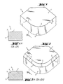
- the insert (2) is shown in FIGS. 1 to 5 as a simple insert (2) and not as an insert. It has a top surface (1) which, according to FIGS. 1, 1A, is delimited by the peripheral, sharp-edged cutting edge (3). In the area of the corners, the cutting edge (3) merges into the corner radius (4). Arranging a simple protective chamfer (5) on the cutting plate (2) results in the cutting edge (3) being displaced into the lower region, as is shown in FIGS. 2 and 2A. If, as shown in FIGS. 3 and 3A, a double chamfer is attached, there is a further displacement of the cutting edge (3) downwards, i. H. in the area where the primary chamfer (6) engages the circumferential boundary surface (11) of the cutting plate (2).
- FIG. 4 represents a special embodiment of FIG. 2.
- the chamfer is designed as a TSD chamfer, that is, as a truncated cone chamfer (8).
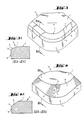
- 5A and 5B illustrate the embodiment according to the invention.
- the secondary bevel (7) closes with an inclination ( ⁇ ) to the top surface (1) which follows the primary chamfer (6) with an inclination ( ⁇ to the top surface 1).
- This latter (6) also follows the corner radius (4, 4 ').
- the secondary chamfer (7) runs straight on both sides in the direction of the corner radius (4) and emerges from it (straight chamfer outlets 10), so it no longer follows the primary chamfer (6) there.
- the primary chamfer (6) of the straight regions (12, 13) there is tracked by the reinforcement region (9) as a reinforced primary chamfer (6 ') to the corner radius region (4, 4').
- the primary chamfer (6 ') extends from the cutting edge (3) to the now raised and at the same time pulled up top boundary edge in the corner radius area (4, 4').
Landscapes
- Engineering & Computer Science (AREA)
- Mechanical Engineering (AREA)
- Milling Processes (AREA)
- Cutting Tools, Boring Holders, And Turrets (AREA)
- Processing Of Stones Or Stones Resemblance Materials (AREA)
- Turning (AREA)
- Crushing And Pulverization Processes (AREA)
- Mechanical Treatment Of Semiconductor (AREA)
- Polishing Bodies And Polishing Tools (AREA)
- Scissors And Nippers (AREA)
Priority Applications (1)
| Application Number | Priority Date | Filing Date | Title |
|---|---|---|---|
| AT89111568T ATE75643T1 (de) | 1988-07-08 | 1989-06-24 | Schneidplatte fuer spanabhebende bearbeitung. |
Applications Claiming Priority (2)
| Application Number | Priority Date | Filing Date | Title |
|---|---|---|---|
| DE3823199 | 1988-07-08 | ||
| DE3823199A DE3823199A1 (de) | 1988-07-08 | 1988-07-08 | Schneidplatte fuer spanabhebende bearbeitung |
Publications (2)
| Publication Number | Publication Date |
|---|---|
| EP0349871A1 true EP0349871A1 (fr) | 1990-01-10 |
| EP0349871B1 EP0349871B1 (fr) | 1992-05-06 |
Family
ID=6358274
Family Applications (1)
| Application Number | Title | Priority Date | Filing Date |
|---|---|---|---|
| EP89111568A Expired - Lifetime EP0349871B1 (fr) | 1988-07-08 | 1989-06-24 | Plaquette de coupe pour usinage de métaux |
Country Status (8)
| Country | Link |
|---|---|
| US (1) | US5006020A (fr) |
| EP (1) | EP0349871B1 (fr) |
| JP (1) | JP2939888B2 (fr) |
| AT (1) | ATE75643T1 (fr) |
| CA (1) | CA1326951C (fr) |
| DE (2) | DE3823199A1 (fr) |
| ES (1) | ES2031662T3 (fr) |
| GR (1) | GR3005311T3 (fr) |
Cited By (7)
| Publication number | Priority date | Publication date | Assignee | Title |
|---|---|---|---|---|
| DE4310131A1 (de) * | 1993-03-29 | 1994-10-06 | Krupp Widia Gmbh | Schneideinsatz |
| EP0654317A1 (fr) * | 1993-10-21 | 1995-05-24 | Sandvik Aktiebolag | Plaquette de coupe pour outil de coupe |
| US5725334A (en) * | 1993-03-29 | 1998-03-10 | Widia Gmbh | Cutting insert |
| WO2008044991A1 (fr) * | 2006-10-13 | 2008-04-17 | Seco Tools Ab | Insert négatif pour usinage par enlèvement de copeaux |
| EP2853328A1 (fr) * | 2013-09-27 | 2015-04-01 | Sandvik Intellectual Property AB | Outil de forage de trou profond |
| CN110944777A (zh) * | 2017-08-02 | 2020-03-31 | 京瓷株式会社 | 切削刀片、切削工具以及切削加工物的制造方法 |
| US20220001455A1 (en) * | 2018-10-29 | 2022-01-06 | Kyocera Corporation | Cutting insert, cutting tool and method for manufacturing machined product |
Families Citing this family (26)
| Publication number | Priority date | Publication date | Assignee | Title |
|---|---|---|---|---|
| SE502196C2 (sv) * | 1990-12-03 | 1995-09-11 | Sandvik Ab | Vändskär med positiv spånvinkel, samt fräsverktyg, företrädesvis för hörnfräsning |
| JP2530764Y2 (ja) * | 1991-03-26 | 1997-03-26 | 三菱マテリアル株式会社 | スローアウエイチツプ |
| SE502541C2 (sv) * | 1992-02-05 | 1995-11-06 | Sandvik Ab | Spånavskiljande skär med exakta lägesbestämmande mått, samt förfarande för dess framställning |
| IL118797A (en) * | 1996-07-05 | 1999-10-28 | Iscar Ltd | Cutting insert |
| DE19855103C2 (de) * | 1998-11-30 | 2001-08-09 | Felix Leeb | Spanabhebendes Schneidwerkzeug |
| AT4435U1 (de) * | 2000-09-25 | 2001-07-25 | Plansee Tizit Ag | Wendeschneidplatte zum drehen |
| JP4228557B2 (ja) * | 2001-02-05 | 2009-02-25 | 三菱マテリアル株式会社 | スローアウェイチップ |
| US7252460B2 (en) * | 2003-03-06 | 2007-08-07 | Stephan Rieth | Indexable tip for beveling by means of a conical milling head |
| SE530153C2 (sv) * | 2005-02-22 | 2008-03-11 | Seco Tools Ab | Skär för svarvning med ett perifert land av konstant bredd |
| SE529146C2 (sv) * | 2005-02-22 | 2007-05-15 | Seco Tools Ab | Skär för svarvning där fasvinkeln vid hörnet uppvisar ett minimum |
| JP4653744B2 (ja) * | 2005-03-16 | 2011-03-16 | 住友電工ハードメタル株式会社 | 高品位・高能率加工用cbn切削工具 |
| DE102008027009B4 (de) * | 2008-06-06 | 2010-08-12 | Kennametal Inc. | Schneideinsatz für ein Zerspanungswerkzeug, sowie Werkzeugsitz und Schneidwerkzeug |
| GB0907737D0 (en) * | 2009-05-06 | 2009-06-10 | Element Six Ltd | An insert for a cutting tool |
| US8672590B2 (en) * | 2010-03-29 | 2014-03-18 | Sumitomo Electric Hardmetal Corp. | Cutting insert |
| SE537377C2 (sv) * | 2012-07-05 | 2015-04-14 | Sandvik Intellectual Property | Skärinsats och fräsverktyg för fräsning av ett spår i ett arbetsstycke |
| SE1350983A1 (sv) * | 2013-08-27 | 2015-02-28 | Sandvik Intellectual Property | Verktyg och skär för skalfräsning |
| WO2016043127A1 (fr) * | 2014-09-16 | 2016-03-24 | 住友電気工業株式会社 | Plaquette de coupe et son procédé de fabrication |
| JP6717939B2 (ja) * | 2016-06-17 | 2020-07-08 | 京セラ株式会社 | 切削インサート、切削工具及び切削加工物の製造方法 |
| EP3260225B1 (fr) * | 2016-06-20 | 2022-11-30 | Sandvik Intellectual Property AB | Insert de tournage |
| JP6930245B2 (ja) * | 2016-06-28 | 2021-09-01 | 三菱マテリアル株式会社 | 切削インサート |
| JP6618025B2 (ja) * | 2016-12-20 | 2019-12-11 | 住友電工ハードメタル株式会社 | 切削工具及びその製造方法 |
| US10631733B2 (en) | 2017-03-13 | 2020-04-28 | Go!Foton Holdings, Inc. | Lens combination for an optical probe and assembly thereof |
| ES2928984T3 (es) * | 2017-06-30 | 2022-11-23 | Seco Tools Ab | Un inserto de corte y un método de fabricación de un inserto de corte |
| KR102214373B1 (ko) * | 2017-10-31 | 2021-02-08 | 스미또모 덴꼬오 하드메탈 가부시끼가이샤 | 절삭 인서트 |
| DE102020117101A1 (de) * | 2020-06-29 | 2021-12-30 | Kennametal Inc. | Schneideinsatz und Zerspanungswerkzeug |
| CN114309682A (zh) | 2020-09-30 | 2022-04-12 | 肯纳金属公司 | 切削刀片 |
Citations (4)
| Publication number | Priority date | Publication date | Assignee | Title |
|---|---|---|---|---|
| GB1578729A (en) * | 1976-06-16 | 1980-11-05 | Lucas Industries Ltd | Tip in a single point turning tool |
| GB2054418A (en) * | 1979-06-08 | 1981-02-18 | Feldmuehle Ag | Cutting plate |
| US4552491A (en) * | 1980-06-23 | 1985-11-12 | United Technologies Corporation | Cutting tool having cylindrical ceramic insert |
| US4681488A (en) * | 1985-07-03 | 1987-07-21 | Santrade Limited | Cutting insert |
Family Cites Families (8)
| Publication number | Priority date | Publication date | Assignee | Title |
|---|---|---|---|---|
| NL153109B (nl) * | 1966-06-01 | 1977-05-16 | Sandco Ltd | Snijelement voor een verspanende gereedschapsmachine. |
| IT973795B (it) * | 1971-12-06 | 1974-06-10 | Bennet T J | Perfezionamento negli elementi taglianti ad inserimento per frese torni e simili |
| DE2544991C2 (de) * | 1975-10-08 | 1981-06-04 | Hertel, Karl, 8500 Nürnberg | Schneideinsatz für die spanabhebende Bearbeitung |
| US4124326A (en) * | 1977-01-03 | 1978-11-07 | The Valeron Corporation | Cutting insert with raised cutting edge |
| US4318318A (en) * | 1977-07-05 | 1982-03-09 | Schott Lawrence A | Cutting tool |
| US4312250A (en) * | 1980-01-16 | 1982-01-26 | Yankoff Gerald K | Cutting insert and method of machining therewith |
| FR2509209A1 (fr) * | 1981-07-10 | 1983-01-14 | Feldmuehle Prod Tech France | Nouveau profil de plaquettes de coupe et autres materiels de coupe en ceramiques ou en cermets |
| JPS60217005A (ja) * | 1984-04-12 | 1985-10-30 | Toshiba Corp | 切削工具 |
-
1988
- 1988-07-08 DE DE3823199A patent/DE3823199A1/de not_active Withdrawn
-
1989
- 1989-06-24 EP EP89111568A patent/EP0349871B1/fr not_active Expired - Lifetime
- 1989-06-24 ES ES198989111568T patent/ES2031662T3/es not_active Expired - Lifetime
- 1989-06-24 AT AT89111568T patent/ATE75643T1/de not_active IP Right Cessation
- 1989-06-24 DE DE8989111568T patent/DE58901316D1/de not_active Expired - Lifetime
- 1989-07-06 US US07/376,354 patent/US5006020A/en not_active Expired - Fee Related
- 1989-07-07 CA CA000605068A patent/CA1326951C/fr not_active Expired - Fee Related
- 1989-07-10 JP JP1175765A patent/JP2939888B2/ja not_active Expired - Lifetime
-
1992
- 1992-07-29 GR GR920401662T patent/GR3005311T3/el unknown
Patent Citations (4)
| Publication number | Priority date | Publication date | Assignee | Title |
|---|---|---|---|---|
| GB1578729A (en) * | 1976-06-16 | 1980-11-05 | Lucas Industries Ltd | Tip in a single point turning tool |
| GB2054418A (en) * | 1979-06-08 | 1981-02-18 | Feldmuehle Ag | Cutting plate |
| US4552491A (en) * | 1980-06-23 | 1985-11-12 | United Technologies Corporation | Cutting tool having cylindrical ceramic insert |
| US4681488A (en) * | 1985-07-03 | 1987-07-21 | Santrade Limited | Cutting insert |
Cited By (9)
| Publication number | Priority date | Publication date | Assignee | Title |
|---|---|---|---|---|
| DE4310131A1 (de) * | 1993-03-29 | 1994-10-06 | Krupp Widia Gmbh | Schneideinsatz |
| US5725334A (en) * | 1993-03-29 | 1998-03-10 | Widia Gmbh | Cutting insert |
| EP0654317A1 (fr) * | 1993-10-21 | 1995-05-24 | Sandvik Aktiebolag | Plaquette de coupe pour outil de coupe |
| WO2008044991A1 (fr) * | 2006-10-13 | 2008-04-17 | Seco Tools Ab | Insert négatif pour usinage par enlèvement de copeaux |
| US7758287B2 (en) | 2006-10-13 | 2010-07-20 | Seco Tools Ab | Negative insert for cutting machining |
| EP2853328A1 (fr) * | 2013-09-27 | 2015-04-01 | Sandvik Intellectual Property AB | Outil de forage de trou profond |
| RU2661684C2 (ru) * | 2013-09-27 | 2018-07-19 | Сандвик Интеллекчуал Проперти Аб | Сверло для глубокого сверления |
| CN110944777A (zh) * | 2017-08-02 | 2020-03-31 | 京瓷株式会社 | 切削刀片、切削工具以及切削加工物的制造方法 |
| US20220001455A1 (en) * | 2018-10-29 | 2022-01-06 | Kyocera Corporation | Cutting insert, cutting tool and method for manufacturing machined product |
Also Published As
| Publication number | Publication date |
|---|---|
| JP2939888B2 (ja) | 1999-08-25 |
| JPH0265904A (ja) | 1990-03-06 |
| ES2031662T3 (es) | 1992-12-16 |
| GR3005311T3 (fr) | 1993-05-24 |
| DE3823199A1 (de) | 1990-01-11 |
| DE58901316D1 (de) | 1992-06-11 |
| US5006020A (en) | 1991-04-09 |
| EP0349871B1 (fr) | 1992-05-06 |
| ATE75643T1 (de) | 1992-05-15 |
| CA1326951C (fr) | 1994-02-15 |
Similar Documents
| Publication | Publication Date | Title |
|---|---|---|
| EP0349871B1 (fr) | Plaquette de coupe pour usinage de métaux | |
| DE69111688T2 (de) | Schneideinsatz für einen Fräser. | |
| DE69521848T2 (de) | Ein drehender Fräser | |
| DE69305812T2 (de) | Schneideinsatz für einen Fräser | |
| EP0742743B1 (fr) | Plaquette amovible et outil associe | |
| DE69311341T2 (de) | Indexierbarer schneideinsatz für drehende schneidwerkzeuge | |
| EP0597871B1 (fr) | Plaquettes de coupe et outil de per age pour le per age de materiau plein | |
| DE69013828T2 (de) | Schneidwerkzeug. | |
| DE69930449T3 (de) | Drehendes Schneidwerkzeug mit Wendeschneideinsatz | |
| DE2615609A1 (de) | Fraeswerkzeug | |
| EP1205274A1 (fr) | Lame de scie à ruban et procédé pour sa fabrication | |
| DE3714533A1 (de) | Fraeser mit schneideinsaetzen | |
| DE1652913A1 (de) | Schleifschneidvorrichtung | |
| DE3621588C2 (fr) | ||
| DE2626335A1 (de) | Schneideinsatz, insbesondere fuer stirnfraeser | |
| DE69324829T2 (de) | Ein Metallschneideinsatz | |
| DE2640474A1 (de) | Abnehmbare schneidplatte zum schaelen von runden stangen auf einer spitzenlosen maschine | |
| EP0073926B1 (fr) | Outil de coupe, en particulier plaquette amovible | |
| DE69410889T2 (de) | Ein verbesserter frässchneideinsatz | |
| EP0287847B1 (fr) | Outil de coupe | |
| EP1031325B1 (fr) | Outil dentaire | |
| EP2790861B1 (fr) | Plaquette de coupe amovible et outil d'usinage par enlèvement de copeaux | |
| WO2004000492A1 (fr) | Plaquette de coupe présentant deux tetes de coupe opposees | |
| DE3420653A1 (de) | Schneid- oder abstechwerkzeug | |
| DE20102269U1 (de) | Senkschraube |
Legal Events
| Date | Code | Title | Description |
|---|---|---|---|
| PUAI | Public reference made under article 153(3) epc to a published international application that has entered the european phase |
Free format text: ORIGINAL CODE: 0009012 |
|
| 17P | Request for examination filed |
Effective date: 19890710 |
|
| AK | Designated contracting states |
Kind code of ref document: A1 Designated state(s): AT BE CH DE ES FR GB GR IT LI LU NL SE |
|
| 17Q | First examination report despatched |
Effective date: 19910425 |
|
| ITF | It: translation for a ep patent filed | ||
| GRAA | (expected) grant |
Free format text: ORIGINAL CODE: 0009210 |
|
| RAP1 | Party data changed (applicant data changed or rights of an application transferred) |
Owner name: STORA FELDMUEHLE AKTIENGESELLSCHAFT |
|
| AK | Designated contracting states |
Kind code of ref document: B1 Designated state(s): AT BE CH DE ES FR GB GR IT LI LU NL SE |
|
| REF | Corresponds to: |
Ref document number: 75643 Country of ref document: AT Date of ref document: 19920515 Kind code of ref document: T |
|
| ITF | It: translation for a ep patent filed | ||
| ET | Fr: translation filed | ||
| REF | Corresponds to: |
Ref document number: 58901316 Country of ref document: DE Date of ref document: 19920611 |
|
| REG | Reference to a national code |
Ref country code: CH Ref legal event code: PUE Owner name: CERASIV GMBH INNOVATIVES KERAMIK-ENGINEERING |
|
| GBT | Gb: translation of ep patent filed (gb section 77(6)(a)/1977) | ||
| RAP2 | Party data changed (patent owner data changed or rights of a patent transferred) |
Owner name: CERASIV GMBH INNOVATIVES KERAMIK-ENGINEERING |
|
| ITPR | It: changes in ownership of a european patent |
Owner name: CESSIONE;CERASIV GMBH INNOVATIVE KERAMIK - ENGINEE |
|
| REG | Reference to a national code |
Ref country code: GB Ref legal event code: 732 |
|
| REG | Reference to a national code |
Ref country code: FR Ref legal event code: TP |
|
| BECA | Be: change of holder's address |
Free format text: 920506 *CERASIV G.M.B.H. INNOVATIVES KERAMIK-ENGINEERING:MUENCHENWERTHER STRASSE 15, D-4000 DUESSELDORF |
|
| BECH | Be: change of holder |
Free format text: 920506 *CERASIV G.M.B.H. INNOVATIVES KERAMIK-ENGINEERING |
|
| REG | Reference to a national code |
Ref country code: CH Ref legal event code: PFA Free format text: CERASIV GMBH INNOVATIVES KERAMIK-ENGINEERING |
|
| REG | Reference to a national code |
Ref country code: GR Ref legal event code: FG4A Free format text: 3005311 |
|
| PLBE | No opposition filed within time limit |
Free format text: ORIGINAL CODE: 0009261 |
|
| STAA | Information on the status of an ep patent application or granted ep patent |
Free format text: STATUS: NO OPPOSITION FILED WITHIN TIME LIMIT |
|
| 26N | No opposition filed | ||
| REG | Reference to a national code |
Ref country code: ES Ref legal event code: PC2A Owner name: CERASIV GMBH INNOVATIVES KERAMIK-ENGINEERING |
|
| NLS | Nl: assignments of ep-patents |
Owner name: CERASIV GMBH INNOVATIVES KERAMIK-ENGINEERING TE PL |
|
| EPTA | Lu: last paid annual fee | ||
| EAL | Se: european patent in force in sweden |
Ref document number: 89111568.5 |
|
| PGFP | Annual fee paid to national office [announced via postgrant information from national office to epo] |
Ref country code: GB Payment date: 20010515 Year of fee payment: 13 |
|
| PGFP | Annual fee paid to national office [announced via postgrant information from national office to epo] |
Ref country code: CH Payment date: 20010517 Year of fee payment: 13 |
|
| PGFP | Annual fee paid to national office [announced via postgrant information from national office to epo] |
Ref country code: AT Payment date: 20010528 Year of fee payment: 13 |
|
| PGFP | Annual fee paid to national office [announced via postgrant information from national office to epo] |
Ref country code: GR Payment date: 20010530 Year of fee payment: 13 |
|
| PGFP | Annual fee paid to national office [announced via postgrant information from national office to epo] |
Ref country code: SE Payment date: 20010531 Year of fee payment: 13 Ref country code: FR Payment date: 20010531 Year of fee payment: 13 |
|
| PGFP | Annual fee paid to national office [announced via postgrant information from national office to epo] |
Ref country code: LU Payment date: 20010606 Year of fee payment: 13 |
|
| PGFP | Annual fee paid to national office [announced via postgrant information from national office to epo] |
Ref country code: ES Payment date: 20010614 Year of fee payment: 13 |
|
| PGFP | Annual fee paid to national office [announced via postgrant information from national office to epo] |
Ref country code: NL Payment date: 20010618 Year of fee payment: 13 |
|
| PGFP | Annual fee paid to national office [announced via postgrant information from national office to epo] |
Ref country code: BE Payment date: 20010621 Year of fee payment: 13 |
|
| PGFP | Annual fee paid to national office [announced via postgrant information from national office to epo] |
Ref country code: DE Payment date: 20010813 Year of fee payment: 13 |
|
| REG | Reference to a national code |
Ref country code: GB Ref legal event code: IF02 |
|
| PG25 | Lapsed in a contracting state [announced via postgrant information from national office to epo] |
Ref country code: LU Free format text: LAPSE BECAUSE OF NON-PAYMENT OF DUE FEES Effective date: 20020624 Ref country code: GB Free format text: LAPSE BECAUSE OF NON-PAYMENT OF DUE FEES Effective date: 20020624 Ref country code: AT Free format text: LAPSE BECAUSE OF NON-PAYMENT OF DUE FEES Effective date: 20020624 |
|
| PG25 | Lapsed in a contracting state [announced via postgrant information from national office to epo] |
Ref country code: SE Free format text: LAPSE BECAUSE OF NON-PAYMENT OF DUE FEES Effective date: 20020625 Ref country code: ES Free format text: LAPSE BECAUSE OF NON-PAYMENT OF DUE FEES Effective date: 20020625 |
|
| PG25 | Lapsed in a contracting state [announced via postgrant information from national office to epo] |
Ref country code: LI Free format text: LAPSE BECAUSE OF NON-PAYMENT OF DUE FEES Effective date: 20020630 Ref country code: CH Free format text: LAPSE BECAUSE OF NON-PAYMENT OF DUE FEES Effective date: 20020630 Ref country code: BE Free format text: LAPSE BECAUSE OF NON-PAYMENT OF DUE FEES Effective date: 20020630 |
|
| BERE | Be: lapsed |
Owner name: *CERASIV G.M.B.H. INNOVATIVES KERAMIK-ENGINEERING Effective date: 20020630 |
|
| PG25 | Lapsed in a contracting state [announced via postgrant information from national office to epo] |
Ref country code: GR Free format text: LAPSE BECAUSE OF NON-PAYMENT OF DUE FEES Effective date: 20021231 |
|
| PG25 | Lapsed in a contracting state [announced via postgrant information from national office to epo] |
Ref country code: NL Free format text: LAPSE BECAUSE OF NON-PAYMENT OF DUE FEES Effective date: 20030101 Ref country code: DE Free format text: LAPSE BECAUSE OF NON-PAYMENT OF DUE FEES Effective date: 20030101 |
|
| EUG | Se: european patent has lapsed | ||
| GBPC | Gb: european patent ceased through non-payment of renewal fee |
Effective date: 20020624 |
|
| REG | Reference to a national code |
Ref country code: CH Ref legal event code: PL |
|
| PG25 | Lapsed in a contracting state [announced via postgrant information from national office to epo] |
Ref country code: FR Free format text: LAPSE BECAUSE OF NON-PAYMENT OF DUE FEES Effective date: 20030228 |
|
| NLV4 | Nl: lapsed or anulled due to non-payment of the annual fee |
Effective date: 20030101 |
|
| REG | Reference to a national code |
Ref country code: FR Ref legal event code: ST |
|
| REG | Reference to a national code |
Ref country code: ES Ref legal event code: FD2A Effective date: 20030711 |
|
| PG25 | Lapsed in a contracting state [announced via postgrant information from national office to epo] |
Ref country code: IT Free format text: LAPSE BECAUSE OF NON-PAYMENT OF DUE FEES;WARNING: LAPSES OF ITALIAN PATENTS WITH EFFECTIVE DATE BEFORE 2007 MAY HAVE OCCURRED AT ANY TIME BEFORE 2007. THE CORRECT EFFECTIVE DATE MAY BE DIFFERENT FROM THE ONE RECORDED. Effective date: 20050624 |