EP0349326A2 - Entwicklungsgerät - Google Patents
Entwicklungsgerät Download PDFInfo
- Publication number
- EP0349326A2 EP0349326A2 EP89306629A EP89306629A EP0349326A2 EP 0349326 A2 EP0349326 A2 EP 0349326A2 EP 89306629 A EP89306629 A EP 89306629A EP 89306629 A EP89306629 A EP 89306629A EP 0349326 A2 EP0349326 A2 EP 0349326A2
- Authority
- EP
- European Patent Office
- Prior art keywords
- developer
- developer carrying
- image bearing
- developing
- carrying member
- Prior art date
- Legal status (The legal status is an assumption and is not a legal conclusion. Google has not performed a legal analysis and makes no representation as to the accuracy of the status listed.)
- Granted
Links
- 230000004907 flux Effects 0.000 claims abstract description 43
- 238000011144 upstream manufacturing Methods 0.000 claims description 14
- 230000001105 regulatory effect Effects 0.000 claims description 13
- 238000011161 development Methods 0.000 claims description 10
- 238000000034 method Methods 0.000 claims description 6
- 239000002245 particle Substances 0.000 description 25
- 239000010410 layer Substances 0.000 description 10
- 238000012546 transfer Methods 0.000 description 7
- 230000005684 electric field Effects 0.000 description 5
- 239000000696 magnetic material Substances 0.000 description 5
- 230000002093 peripheral effect Effects 0.000 description 5
- 238000003756 stirring Methods 0.000 description 5
- 230000009471 action Effects 0.000 description 4
- 239000000463 material Substances 0.000 description 4
- 238000005259 measurement Methods 0.000 description 4
- 229910000859 α-Fe Inorganic materials 0.000 description 4
- XEEYBQQBJWHFJM-UHFFFAOYSA-N Iron Chemical compound [Fe] XEEYBQQBJWHFJM-UHFFFAOYSA-N 0.000 description 2
- 230000006866 deterioration Effects 0.000 description 2
- 230000000717 retained effect Effects 0.000 description 2
- 229910001220 stainless steel Inorganic materials 0.000 description 2
- 239000010935 stainless steel Substances 0.000 description 2
- XAGFODPZIPBFFR-UHFFFAOYSA-N aluminium Chemical compound [Al] XAGFODPZIPBFFR-UHFFFAOYSA-N 0.000 description 1
- 229910052782 aluminium Inorganic materials 0.000 description 1
- 238000000418 atomic force spectrum Methods 0.000 description 1
- 230000008859 change Effects 0.000 description 1
- 239000011247 coating layer Substances 0.000 description 1
- 230000003247 decreasing effect Effects 0.000 description 1
- 230000007547 defect Effects 0.000 description 1
- 230000001419 dependent effect Effects 0.000 description 1
- 230000008021 deposition Effects 0.000 description 1
- 238000011835 investigation Methods 0.000 description 1
- 229910052742 iron Inorganic materials 0.000 description 1
- 238000012986 modification Methods 0.000 description 1
- 230000004048 modification Effects 0.000 description 1
- 230000008569 process Effects 0.000 description 1
- 230000009467 reduction Effects 0.000 description 1
- 239000007787 solid Substances 0.000 description 1
Images


Classifications
-
- B—PERFORMING OPERATIONS; TRANSPORTING
- B82—NANOTECHNOLOGY
- B82Y—SPECIFIC USES OR APPLICATIONS OF NANOSTRUCTURES; MEASUREMENT OR ANALYSIS OF NANOSTRUCTURES; MANUFACTURE OR TREATMENT OF NANOSTRUCTURES
- B82Y15/00—Nanotechnology for interacting, sensing or actuating, e.g. quantum dots as markers in protein assays or molecular motors
-
- G—PHYSICS
- G03—PHOTOGRAPHY; CINEMATOGRAPHY; ANALOGOUS TECHNIQUES USING WAVES OTHER THAN OPTICAL WAVES; ELECTROGRAPHY; HOLOGRAPHY
- G03G—ELECTROGRAPHY; ELECTROPHOTOGRAPHY; MAGNETOGRAPHY
- G03G15/00—Apparatus for electrographic processes using a charge pattern
- G03G15/06—Apparatus for electrographic processes using a charge pattern for developing
- G03G15/08—Apparatus for electrographic processes using a charge pattern for developing using a solid developer, e.g. powder developer
- G03G15/09—Apparatus for electrographic processes using a charge pattern for developing using a solid developer, e.g. powder developer using magnetic brush
- G03G15/0921—Details concerning the magnetic brush roller structure, e.g. magnet configuration
Definitions
- the present invention relates to a developing apparatus for developing an electrostatic latent image formed on an image bearing member in an image forming apparatus such as an electrophotographic copying machine, an electrophotographic laser beam printer, an LED printer, an LCS printer and a multi-stylus type electrostatic printer.
- an image forming apparatus such as an electrophotographic copying machine, an electrophotographic laser beam printer, an LED printer, an LCS printer and a multi-stylus type electrostatic printer.
- a type of developing apparatus wherein a layer of developer is formed on the developer carrying member in a thickness smaller than a minimum clearance between the developer carrying member and the image bearing member, and the developer is transferred from the layer to the image bearing member to develop the latent image thereon.
- Many of such developing apparatuses each comprise a stationary magnetic field generating member (magnet) and a developer carrying member of non-magnetic material rotated around the outer periphery of the magnetic field generating member.
- the developer carrying member is faced to the image bearing member.
- the developer is supplied onto the developer carrying surface and is carried thereon to a developing zone where it is faced to the image bearing member to develop the latent image.
- FIG. 1A an enlarged view of a good visualized (developed) image is indicated by a reference 100 in Figure 1A.
- Figure 1B shows an enlarged view of an image 101 having tails, wherein developer particles (toner) are deposited in the form of tails 101A in a line or dots, extending in the direction opposite to the movement direction d of the image bearing member (the member to be developed).
- the developer particles are scattered in fine spots 101B around the visualized image 101.
- a magnetic field effective to erect the magnetic brush of the developer from the developer carrying surface is formed in the developing zone, so that the developer particles can be easily released from the developer carrying member.
- the inventor thought that the promotion of the release of the developer particles from the developer carrying member was a cause of the tails and the scattered spots. As a result of various investigations, it has been found that most of the developer particles forming the tails and the scattered spots are those which are transferred from the developer carrying member to be image bearing member in the latter part of the developing process.
- the magnetic confining force in the direction perpendicular to the developer carrying member surface in the present invention is made larger at the downstream side of the position where the image bearing member and the developer carrying member are closest than at the closest position, by which such release of the developer particles from the developer carrying member as to cause the tails and scattered spot is constrained.
- the developer particles once deposited on the image bearing member as the tails and the scattered spots are more easily returned to the developer carrying member.
- distribution shape of the perpendicular magnetic confining force around the periphery of the developer carrying member is not analogous to the distribution shape of the perpendicular magnetic flux density therearound.
- FIG. 2 there is shown a developing apparatus using a one component magnetic developer, which does not contain carrier particles but contains magnetic toner.
- An image bearing member B such as an electrophotographic photosensitive drum to be developed by the developing apparatus is designated by a reference character B.
- the image bearing member B is rotatable at a predetermined peripheral speed in a direction indicated by an arrow d.
- an electrostatic latent image is formed by an unshown latent image forming means.
- the latent image is visualized sequentially with toner by a developing device A.
- the developed image is transferred onto a transfer material in an unshown transfer station, and the transferred image is fixed into permanent image on the transfer material surface at an unshown image fixing station.
- the transfer material is discharged as a record (copy).
- the developing apparatus A comprises a developer container 1, a developing sleeve (cylinder) functioning as the developer carrying member.
- the developing sleeve 2 is rotatably and horizontally supported at the front side of the developer container 1, and substantially a left half of its periphery is exposed outside the container, while substantially the right half thereof is in the container 1.
- the developing sleeve 2 is made of non-magnetic material such as aluminum and stainless steel (SUS) and is rotatingly driven from an unshown drive transmitting system about an axis of the sleeve 2 in a direction C at a predetermined peripheral speed.
- the surface of the image bearing member B and the exposed surface of the developing sleeve 2 are faced with a predetermined small clearance (the minimum clearances 50 - 100 microns), and the facing portion constitute a developing zone a .
- the toner is supplied from the sleeve 2 to the image bearing member so that the latent image is developed.
- the developing apparatus further comprises a magnet roller 3 functioning as the magnetic field generating means contained within the developing sleeve 2.
- the magnetic roller is not rotatable, so that the developing sleeve 2 revolves around the roller 3.
- Magnets 3a, 3b, 3c and 3d are magnets providing magnetic poles at predetermined positions adjacent the periphery of the roller 3.
- the magnet 3a is disposed adjacent to the developing zone a and functions as a developing electrode. More particularly, the magnetic pole 3a formed a magnetic field effective to erect a magnetic brush of the developer on the surface of the sleeve 2 in the developing zone a .
- the peak of the magnetic flux density, in the direction perpendicular to the peripheral surface of the sleeve 2, of the magnetic field, that is the peak of the magnetic flux density effective to erect the magnetic brush on the surface of the sleeve 2, exists in the developing zone a .
- the magnet 3b (cutting pole) functions to regulate the developer and is disposed adjacent a bottom edge of a developer layer regulating blade 4, the bottom edge being faced with a predetermined small clearance on the top part of the developing sleeve 2.
- the blade 4 is preferably made of magnetic material such as iron. Then, a magnetic field produced by the magnetic pole 3b is concentrated on the blade 4, and the concentrated magnetic field serves to form a thin layer of the magnetic developer (U.S. Patent No. 4,387,664).
- the developer layer thickness regulating member may be in the form of an elastic blade press-contacted to the sleeve 2 (U.S. Patent No. 4,458,627).
- Magnet 3c and 3d are disposed adjacent the right hand side and the bottom side of the developing sleeve 2, respectively, and function to convey the developer.
- the one component magnetic developer 5 is contained in the container 1.
- the container is equipped therein with a developer stirring rod and an auxiliary stirring rod rotated in the directions indicated by arrows.
- the developer 5 in the container 1 is sufficiently stirred and mixed by the rotation of the stirring rod 6, and is conveyed toward the right half periphery of the developing sleeve 2.
- the auxiliary stirring rod 7 serves to move the developer present at the rear side of the container toward the stirring rod 6.
- Substantially the right half of the periphery of the developing sleeve 2 is always in contact with the developer 5 in the container 1 so as to be supplied with the developer, and the developer adjacent to the developing sleeve surface is attracted on the sleeve surface 2 and is retained thereon by the magnetic force provided by the magnet role 3.
- the retained layer of the developer is conveyed by the rotating sleeve 2, and the thickness thereof is regulated by passing through the clearance between the sleeve 2 and the blade 4, by which it is regulated into a thin coating layer having a uniform thickness.
- the thin layer is carried by the continuing rotation of the sleeve 2 into the developing zone a .
- the developer carried on the developing sleeve 2 is transferred and deposited onto the image bearing member correspondingly to the latent image pattern of the image bearing member B by the movement of the surface of the image bearing member B through the developing zone a , the latent image is sequentially visualized (developed).
- the developer layer thickness regulating member 4 regulates the developer layer into a thickness which is smaller than the minimum clearance between the sleeve 2 and the image bearing member B in the developing zone a .
- the sleeve 8 is supplied from the voltage source 8 with an alternating voltage in the form of a sine wave, rectangular wave or triangular wave or the like or such an AC voltage superposed with a DC voltage, by which an alternating electric field is formed in the developing zone a .
- the AC voltage has a peak-to-peak voltage (Vpp) which is preferably larger than an absolute value of a difference between the maximum potential of the latent image and a minimum potential thereof, and the DC voltage (the center of the alternating bias voltage) is preferably between the maximum potential and the minimum potential.
- Vpp peak-to-peak voltage
- the maximum and minimum levels of the bias voltage is preferably outside the range between the maximum potential and the minimum potential of the latent image.
- the toner In a regular development wherein the toner is deposited on the maximum potential portion of the latent image, the toner is charged to the polarity opposite to that of the latent image, whereas in a reverse-development wherein the toner is deposited to the minimum potential portion of the latent image, the toner is charged to the same polarity as the polarity of the latent image potential.
- the toner When one component developer is used, the toner is triboelectrically charged to the proper polarity described above by the friction with the sleeve 2.
- the alternating electric field functions to promote the release of the developer from the sleeve, and therefore, the above-described tails and scattered spots are relatively easily produced.
- Overcharged toner particles, insufficiently charged toner particles, the toner particles charged to the polarity opposite to the desired polarity are difficult to release from the image bearing member once they are deposited on the background of the latent image, even by the alternating electric field, and therefore, they tend to remain as the tails and scattered spots.
- the present invention is effective to solve these problems.
- the developer not consumed for the development is returned into the container 1, being carried on the developing sleeve surface which continuously rotates.
- the visualized image on the image bearing member B is sequentially transferred onto a transfer material through an unshown transfer station.
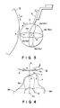
- Figure 3 shows a distribution, along the circumferential periphery of the developing sleeve, of a component of the magnetic flux density on the sleeve surface in the direction perpendicular to the surface of the developing sleeve (perpendicular component magnetic flux density or perpendicular magnetic flux density), corresponding to the stationary magnetic poles 3a, 3b, 3c and 3d of the magnet role 3. That is, designated by references 9a, 9b, 9c and 9d are density distribution of the perpendicular component magnetic flux of the developing pole 3a, the cutting pole 3b, the conveying poles 3b and 3d. Designated by reference Q represents 0 Gauss line.
- the distribution 9a is the distribution of the perpendicular magnetic flux density effective to erect the developer on the sleeve surface in the developing zone, and has a peak e in the developing zone a .
- Figure 4 shows the perpendicular magnetic flux density in the neighborhood of the developing zone a and a distribution F of a magnetic confining force in the perpendicular direction.
- Designated by a reference Q indicates 0 magnetic flux density and 0 magnetic confining force.
- the magnetic confining force is the force for magnetically attracting the developer particles toward the axis 2a of the sleeve 2.
- the configuration of the magnetic confining force distribution along the circumference of the sleeve is not analogous to the configuration of the perpendicular flux density distribution along the circumference.
- the peak position e of the magnetic flux density 9a is on a line b connecting the axis of the image bearing member B (geometrical center of the drum) and the axis 2a of the developing sleeve 2.
- Figure 7 shows an example of the distribution F′ of the perpendicular magnetic confining force along the circumferential periphery of the sleeve in the developing zone a in a conventional developing apparatus of the same type.
- the perpendicular magnetic confining force distribution or profile F is as shown in Figure 4, the perpendicular confining force is stronger in the downstream side f of the position where the image bearing member B and the developing sleeve 2 are closest in the developing zone, and therefore, the developer particles receive stronger forces toward the developing sleeve 2 in the downstream side f.
- the chains of the developer particles by the developing pole 3a is immediately attracted to the developing sleeve 2 side. Therefore, excessive developer particles attributable to the tails, scattered spots and thinning of the image are difficult to reach the image bearing member B.
- the developer particles which can be a cause of the tails, scattered spots and the thinning and which has been deposited on the image bearing member are retracted back to the developing sleeve by the magnetic confining force. It is considered that this is the reason why the tails and scattered spots are prevented.
- the perpendicular magnetic confining force F is larger upstream and downstream of the line b on which the image bearing member and the sleeve are closest with respect to the movement direction of the image bearing member than at the line b.
- the magnetic confining force distribution adjacent the developing zone a is as shown in Figure 5 by a reference F
- the magnetic confining force is strong in the vicinity of the position where the developing action starts, and therefore, movement of the one component magnetic developer on the developing sleeve 2 toward the image bearing member B is restrained by the magnetic confining force, so that the amount of the developer more than necessary is prevented from being deposited on the image bearing member B.
- the function is provided to restrain the movement of the developer to the image bearing member B more than necessary, which can be a cause of the tails and scattered spots.
- the magnetic confining force is too strong adjacent the central portion of the developing zone A (line b), the restraint to the developer is so strong that the image density is decreased too much. Therefore, adjacent the center of the developing zone, it is preferable that the magnetic confining force is weaker than adjacent the development starting region and than adjacent the development ending position.
- the peak e of the perpendicular magnetic flux density 9a is on the line b, but this is not limiting, and it may be slightly shifted toward upstream or downstream of the line b if the peak e is in the developing zone a .
- the magnetic confining force is stronger in the upstream and downstream sides of the peak position e with respect to the movement direction of the image bearing member than at the peak position e of the magnetic flux density.
- the position of a peak g of the magnetic confining force in the downstream side of the line b is preferably adjacent a finishing end a2 in the developing zone. More particularly, the peak position g is in the region between a point away from the finishing end a2 toward upstream and downstream by l 2 x (1/3), respectively, where l 2 is a distance from the line b to the end a2.
- the position of the peak h of the magnetic confining force in the upstream side of the line b is preferably adjacent to the development starting end a1.
- the peak h is preferably in the region between a point away from the starting end a1 toward upstream and downstream by distance l 1 x (1/3), respectively, with respect to the movement direction of the image bearing member, where l 1 is a distance between the line b and the starting end a1.
- W1 ⁇ 1/ ⁇ 1 ⁇ 0.5.
- W1 and W2 are not less than 0.65.
- ⁇ 1, ⁇ 2, ⁇ 1 and ⁇ 2 are angles seen from the rotational center of the sleeve.
- ⁇ 1, ⁇ 2, ⁇ 1 and ⁇ 2 are such angles between points i and e, between points e and j, between points k and e and between points e and l , respectively.
- the point i is the point upstream of the point e with respect to the image bearing member movement direction where the perpendicular magnetic flux density 9a is 0;
- the point j is a point downstream of the point e where the perpendicular magnetic flux density 9a is 0;
- points k and l are points where the perpendicular magnetic flux density 9a is one half that at the peak e.
- the sleeve 2 rotates to provide the same peripheral movement as the image bearing member B in the developing zone a . However, it may be rotated in the opposite direction.
- the ratio of the speeds of the sleeve 2 and the image bearing member B can be properly set to provide a desired density of the developed image.
- the magnetic flux density distribution and the magnetic confining force distribution described above can be provided by one or more of bonding plural magnets in proper orientation, magnetizing a magnetic member in a form of a roller in proper pattern, partly cutting the magnet produced in the above manner and forming one or more grooves therein.
- the profile of the magnetic confining force distribution is dependent on the profile of the magnetic flux density distribution.
- the present invention is applicable to a non-contact type developing apparatus using two component developer containing magnetic carrier particles and non-magnetic toner particles wherein a layer of the developer is formed into a thickness smaller than the minimum clearance between the image bearing member and the sleeve.
- the alternating electric field is formed in the developing zone.
- a small spherical ball 10 of magnetic material is disposed adjacent to the developing sleeve 2.
- the ball 10 is fixed on a thin shaft of non-magnetic material.
- the shaft 11 extends along a vertical line passing through an axis of the developing sleeve as shown in Figure 9B.
- the other end of the shaft 11 is fixed and connected to a strain gauge 12.
- the magnetic ball 10 is so adjusted that it is sensitive only to a component, in the direction perpendicular to the surface of the sleeve, of the magnetic confining force provided by the magnetic field formed by the magnetic field generating means 3 in the developing sleeve.
- the above-described stationary magnet 3a, 3b, 3c and 3d are mounted for relative coaxial rotation.
- the distribution, along the circumferential periphery of the sleeve, of the magnetic confining force is measured while the magnet is rotated coaxially with the sleeve 2.
- the output of the strain gauge 12 is connected to an amplifier through a bridge 13.
- the amplifier 14 is connected with a recorder 15 so that the distribution along the circumference can be recorded in accordance with the output indicative of the perpendicular magnetic confining force.
- the magnetic ball 10 was made of ferrite and had a diameter approximately 1 mm, and the shaft 11 was made of a stainless steel rod having a diameter of 1 mm (non-magnetic).
- the clearance between the magnetic ball 10 and the sleeve 2 was set approximately 0.5 mm.
- the strain gauge 12 was 120 T-5B available from KYOWA DENGYO KABUSHIKI KAISHA, Japan; the amplifier 14 was DPM-305A available from the same; and the recorder 15 was XY-PLOTTER FP5301R available from GRAPHTEC, INC.
- the magnetic ball 10 is a toner particle actually used in the development, but the actual toner particles have diameter of approximately 10 microns which is too small, and the force received by the toner is so small that a sufficiently sensitive strange gauge 12 is not available at present.
- the output changes with the change of the distance between the magnetic ball 10 and the developing sleeve 2.
- the distribution profile is substantially an analogous even if the distance is changed by 0 - 2 mm.
- the distance 0 mm means that the developing sleeve is removed to expose the magnet, and then the measurement is carried out.
- the distance between the image bearing member B and the developing sleeve 2 is approximately 50 microns - 1 mm, and the magnetic flux density distribution measured under those conditions is an analogous distribution of the force applied to the toner at the time of the actual development action. More particularly, when the magnetic ball 10 is a ferrite ball having a diameter of approximately 1 mm, and the clearance between the ferrite ball 10 and the developing sleeve 2 is 0.5 mm upon the measurement of the magnetic confining force, the force received by the ferrite ball is not exactly the same as the force received by a toner particle, but it exhibits an analogous circumference distribution in the magnetic confining force received by the toner particle.
- the tails and scattered spots are prevented from being produced.
- other deteriorations of the image such as reduction of an image density of a fine line extending in a direction perpendicular to the movement direction of the image bearing member, thinning of a fine line and increase of an image density at a trailing edge portion of the solid black image which are occurred in the development.
Landscapes
- Chemical & Material Sciences (AREA)
- Engineering & Computer Science (AREA)
- Nanotechnology (AREA)
- Physics & Mathematics (AREA)
- General Physics & Mathematics (AREA)
- Health & Medical Sciences (AREA)
- Life Sciences & Earth Sciences (AREA)
- General Health & Medical Sciences (AREA)
- Molecular Biology (AREA)
- Crystallography & Structural Chemistry (AREA)
- Dry Development In Electrophotography (AREA)
- Magnetic Brush Developing In Electrophotography (AREA)
Applications Claiming Priority (4)
| Application Number | Priority Date | Filing Date | Title |
|---|---|---|---|
| JP164140/88 | 1988-07-01 | ||
| JP16414088 | 1988-07-01 | ||
| JP16414188 | 1988-07-01 | ||
| JP164141/88 | 1988-07-01 |
Publications (3)
| Publication Number | Publication Date |
|---|---|
| EP0349326A2 true EP0349326A2 (de) | 1990-01-03 |
| EP0349326A3 EP0349326A3 (en) | 1990-11-28 |
| EP0349326B1 EP0349326B1 (de) | 1994-01-05 |
Family
ID=26489347
Family Applications (1)
| Application Number | Title | Priority Date | Filing Date |
|---|---|---|---|
| EP89306629A Expired - Lifetime EP0349326B1 (de) | 1988-07-01 | 1989-06-29 | Entwicklungsgerät |
Country Status (3)
| Country | Link |
|---|---|
| US (1) | US4960070A (de) |
| EP (1) | EP0349326B1 (de) |
| DE (1) | DE68912004T2 (de) |
Cited By (2)
| Publication number | Priority date | Publication date | Assignee | Title |
|---|---|---|---|---|
| EP0636950A3 (de) * | 1993-07-27 | 1995-04-12 | Canon Kk | Entwicklungsgerät mit einer sich drehenden Entwicklerzufuhreinheit einer Entwicklerträgereinheit. |
| CN109074016A (zh) * | 2016-03-08 | 2018-12-21 | 佳能株式会社 | 显影设备 |
Families Citing this family (9)
| Publication number | Priority date | Publication date | Assignee | Title |
|---|---|---|---|---|
| JPH034264A (ja) * | 1989-05-31 | 1991-01-10 | Canon Inc | 磁気ブラシ現像装置 |
| US5129357A (en) * | 1990-01-12 | 1992-07-14 | Canon Kabushiki Kaisha | Magnetic brush developing apparatus wherein a point of inflection in the magnetic flux density distribution is provided upstream from the maximum flux density position |
| US5424489A (en) * | 1990-09-03 | 1995-06-13 | Fujitsu Limited | Magnetic brush developing apparatus |
| US5396026A (en) * | 1990-09-03 | 1995-03-07 | Fujitsu Limited | Magnetic brush developing apparatus |
| US5498837A (en) * | 1992-08-13 | 1996-03-12 | Hitachi Metals, Ltd. | Sleeve for developing roll member |
| US5491541A (en) * | 1992-11-12 | 1996-02-13 | Minolta Camera Kabushiki Kaisha | Developing apparatus having adjacent similar magnetic poles |
| JP3060763B2 (ja) * | 1993-01-28 | 2000-07-10 | ミノルタ株式会社 | 現像装置 |
| JP3334033B2 (ja) * | 1996-10-25 | 2002-10-15 | ミノルタ株式会社 | 現像装置 |
| JP5071424B2 (ja) * | 2009-03-26 | 2012-11-14 | 富士ゼロックス株式会社 | 現像装置及び画像形成装置 |
Family Cites Families (4)
| Publication number | Priority date | Publication date | Assignee | Title |
|---|---|---|---|---|
| UST959003I4 (en) * | 1976-10-05 | 1977-06-07 | Electrostatic process development apparatus | |
| CA1135046A (en) * | 1978-01-11 | 1982-11-09 | Kouji Suzuki | Magnetic brush development apparatus |
| JPS56133761A (en) * | 1980-03-25 | 1981-10-20 | Ricoh Co Ltd | Magnetic brush developing device |
| US4833504A (en) * | 1987-08-31 | 1989-05-23 | Xerox Corporation | Single pass highlight color printer including a scavengeless developer housing |
-
1989
- 1989-06-29 DE DE89306629T patent/DE68912004T2/de not_active Expired - Fee Related
- 1989-06-29 EP EP89306629A patent/EP0349326B1/de not_active Expired - Lifetime
- 1989-06-30 US US07/373,580 patent/US4960070A/en not_active Expired - Lifetime
Cited By (7)
| Publication number | Priority date | Publication date | Assignee | Title |
|---|---|---|---|---|
| EP0636950A3 (de) * | 1993-07-27 | 1995-04-12 | Canon Kk | Entwicklungsgerät mit einer sich drehenden Entwicklerzufuhreinheit einer Entwicklerträgereinheit. |
| US5621505A (en) * | 1993-07-27 | 1997-04-15 | Canon Kabushiki Kaisha | Developing apparatus having rotatable developer supply member for developer carrying member |
| CN109074016A (zh) * | 2016-03-08 | 2018-12-21 | 佳能株式会社 | 显影设备 |
| EP3428732A4 (de) * | 2016-03-08 | 2019-11-13 | C/o Canon Kabushiki Kaisha | Entwicklungsvorrichtung |
| US10768552B2 (en) | 2016-03-08 | 2020-09-08 | Canon Kabushiki Kaisha | Developing device |
| US11262672B2 (en) | 2016-03-08 | 2022-03-01 | Canon Kabushiki Kaisha | Developing device |
| EP4027203A1 (de) * | 2016-03-08 | 2022-07-13 | Canon Kabushiki Kaisha | Entwicklungsvorrichtung |
Also Published As
| Publication number | Publication date |
|---|---|
| EP0349326A3 (en) | 1990-11-28 |
| DE68912004T2 (de) | 1994-05-05 |
| EP0349326B1 (de) | 1994-01-05 |
| DE68912004D1 (de) | 1994-02-17 |
| US4960070A (en) | 1990-10-02 |
Similar Documents
| Publication | Publication Date | Title |
|---|---|---|
| US5267007A (en) | Magnetic seal for preventing developer from leaking out of the longitudinal ends of a rotatable member | |
| JP2003005530A (ja) | 現像装置及び画像形成装置 | |
| EP0349326B1 (de) | Entwicklungsgerät | |
| US6526247B2 (en) | Electrostatic image developing process with optimized setpoints | |
| US4994859A (en) | Power cloud developing apparatus with a first and second electric field curtain generating means | |
| US6882818B2 (en) | Image forming apparatus having a development apparatus forming a magnetic brush separated from a latent image carrier outside a development area | |
| US7155150B2 (en) | Method and apparatus for developing a latent image using toner grains constituting a developer | |
| JPH087503B2 (ja) | 現像装置 | |
| JP4647123B2 (ja) | 現像方法、現像装置及び画像形成装置 | |
| JP4082552B2 (ja) | 画像形成装置 | |
| JP4176266B2 (ja) | 画像形成装置 | |
| JP2000122403A (ja) | 現像装置 | |
| JP2000305361A (ja) | 画像形成装置 | |
| JP3270663B2 (ja) | 現像装置 | |
| JPH11174848A (ja) | 現像装置及び画像形成装置 | |
| JP2001356604A (ja) | 画像形成装置 | |
| JP2002287501A (ja) | 現像装置及び画像形成装置 | |
| JPH08137255A (ja) | 現像装置 | |
| JPH1173020A (ja) | 二成分現像方法及びこれに用いられる現像装置 | |
| JP2003107912A (ja) | 現像装置、及びこれを用いた画像形成装置 | |
| JPH0695510A (ja) | 現像方法 | |
| JPH0736266A (ja) | 現像装置 | |
| JPH02120773A (ja) | 現像装置 | |
| JPH11352772A (ja) | 現像装置及び画像形成装置 | |
| JPH0344675A (ja) | 現像装置 |
Legal Events
| Date | Code | Title | Description |
|---|---|---|---|
| PUAI | Public reference made under article 153(3) epc to a published international application that has entered the european phase |
Free format text: ORIGINAL CODE: 0009012 |
|
| AK | Designated contracting states |
Kind code of ref document: A2 Designated state(s): DE FR GB IT |
|
| PUAL | Search report despatched |
Free format text: ORIGINAL CODE: 0009013 |
|
| AK | Designated contracting states |
Kind code of ref document: A3 Designated state(s): DE FR GB IT |
|
| 17P | Request for examination filed |
Effective date: 19901231 |
|
| 17Q | First examination report despatched |
Effective date: 19920805 |
|
| GRAA | (expected) grant |
Free format text: ORIGINAL CODE: 0009210 |
|
| AK | Designated contracting states |
Kind code of ref document: B1 Designated state(s): DE FR GB IT |
|
| REF | Corresponds to: |
Ref document number: 68912004 Country of ref document: DE Date of ref document: 19940217 |
|
| ITF | It: translation for a ep patent filed | ||
| ET | Fr: translation filed | ||
| ITTA | It: last paid annual fee | ||
| PLBE | No opposition filed within time limit |
Free format text: ORIGINAL CODE: 0009261 |
|
| STAA | Information on the status of an ep patent application or granted ep patent |
Free format text: STATUS: NO OPPOSITION FILED WITHIN TIME LIMIT |
|
| 26N | No opposition filed | ||
| REG | Reference to a national code |
Ref country code: GB Ref legal event code: IF02 |
|
| PGFP | Annual fee paid to national office [announced via postgrant information from national office to epo] |
Ref country code: DE Payment date: 20070821 Year of fee payment: 19 |
|
| PGFP | Annual fee paid to national office [announced via postgrant information from national office to epo] |
Ref country code: GB Payment date: 20070618 Year of fee payment: 19 |
|
| PGFP | Annual fee paid to national office [announced via postgrant information from national office to epo] |
Ref country code: IT Payment date: 20070611 Year of fee payment: 19 |
|
| PGFP | Annual fee paid to national office [announced via postgrant information from national office to epo] |
Ref country code: FR Payment date: 20070625 Year of fee payment: 19 |
|
| GBPC | Gb: european patent ceased through non-payment of renewal fee |
Effective date: 20080629 |
|
| REG | Reference to a national code |
Ref country code: FR Ref legal event code: ST Effective date: 20090228 |
|
| PG25 | Lapsed in a contracting state [announced via postgrant information from national office to epo] |
Ref country code: DE Free format text: LAPSE BECAUSE OF NON-PAYMENT OF DUE FEES Effective date: 20090101 |
|
| PG25 | Lapsed in a contracting state [announced via postgrant information from national office to epo] |
Ref country code: GB Free format text: LAPSE BECAUSE OF NON-PAYMENT OF DUE FEES Effective date: 20080629 |
|
| PG25 | Lapsed in a contracting state [announced via postgrant information from national office to epo] |
Ref country code: IT Free format text: LAPSE BECAUSE OF NON-PAYMENT OF DUE FEES Effective date: 20080629 Ref country code: FR Free format text: LAPSE BECAUSE OF NON-PAYMENT OF DUE FEES Effective date: 20080630 |