EP0349213A2 - Kochherde - Google Patents
Kochherde Download PDFInfo
- Publication number
- EP0349213A2 EP0349213A2 EP89306384A EP89306384A EP0349213A2 EP 0349213 A2 EP0349213 A2 EP 0349213A2 EP 89306384 A EP89306384 A EP 89306384A EP 89306384 A EP89306384 A EP 89306384A EP 0349213 A2 EP0349213 A2 EP 0349213A2
- Authority
- EP
- European Patent Office
- Prior art keywords
- oven
- cavity
- cooking
- gas burner
- oven cavity
- Prior art date
- Legal status (The legal status is an assumption and is not a legal conclusion. Google has not performed a legal analysis and makes no representation as to the accuracy of the status listed.)
- Withdrawn
Links
Images
Classifications
-
- H—ELECTRICITY
- H05—ELECTRIC TECHNIQUES NOT OTHERWISE PROVIDED FOR
- H05B—ELECTRIC HEATING; ELECTRIC LIGHT SOURCES NOT OTHERWISE PROVIDED FOR; CIRCUIT ARRANGEMENTS FOR ELECTRIC LIGHT SOURCES, IN GENERAL
- H05B6/00—Heating by electric, magnetic or electromagnetic fields
- H05B6/64—Heating using microwaves
- H05B6/647—Aspects related to microwave heating combined with other heating techniques
- H05B6/6473—Aspects related to microwave heating combined with other heating techniques combined with convection heating
-
- F—MECHANICAL ENGINEERING; LIGHTING; HEATING; WEAPONS; BLASTING
- F24—HEATING; RANGES; VENTILATING
- F24C—DOMESTIC STOVES OR RANGES ; DETAILS OF DOMESTIC STOVES OR RANGES, OF GENERAL APPLICATION
- F24C1/00—Stoves or ranges in which the fuel or energy supply is not restricted to solid fuel or to a type covered by a single one of the following groups F24C3/00 - F24C9/00; Stoves or ranges in which the type of fuel or energy supply is not specified
- F24C1/02—Stoves or ranges in which the fuel or energy supply is not restricted to solid fuel or to a type covered by a single one of the following groups F24C3/00 - F24C9/00; Stoves or ranges in which the type of fuel or energy supply is not specified adapted for the use of two or more kinds of fuel or energy supply
- F24C1/04—Stoves or ranges in which the fuel or energy supply is not restricted to solid fuel or to a type covered by a single one of the following groups F24C3/00 - F24C9/00; Stoves or ranges in which the type of fuel or energy supply is not specified adapted for the use of two or more kinds of fuel or energy supply simultaneously
-
- F—MECHANICAL ENGINEERING; LIGHTING; HEATING; WEAPONS; BLASTING
- F24—HEATING; RANGES; VENTILATING
- F24C—DOMESTIC STOVES OR RANGES ; DETAILS OF DOMESTIC STOVES OR RANGES, OF GENERAL APPLICATION
- F24C15/00—Details
- F24C15/32—Arrangements of ducts for hot gases, e.g. in or around baking ovens
- F24C15/322—Arrangements of ducts for hot gases, e.g. in or around baking ovens with forced circulation
- F24C15/325—Arrangements of ducts for hot gases, e.g. in or around baking ovens with forced circulation electrically-heated
-
- F—MECHANICAL ENGINEERING; LIGHTING; HEATING; WEAPONS; BLASTING
- F24—HEATING; RANGES; VENTILATING
- F24C—DOMESTIC STOVES OR RANGES ; DETAILS OF DOMESTIC STOVES OR RANGES, OF GENERAL APPLICATION
- F24C3/00—Stoves or ranges for gaseous fuels
- F24C3/12—Arrangement or mounting of control or safety devices
- F24C3/126—Arrangement or mounting of control or safety devices on ranges
- F24C3/128—Arrangement or mounting of control or safety devices on ranges in baking ovens
Definitions
- This invention relates to cooking ovens and is especially applicable to combination microwave cooking ovens.
- a combination microwave cooking oven combines the advantages of a microwave oven and a normal gas or electric convection oven, by incorporating into the microwave oven either an electric heater or a gas burner.
- An internal fan may also be provided to afford the advantages of a fanned oven.
- microwave energy is available immediately for cooking, it can take up to approximately 15 minutes for the electric heater or the gas burner, as the case may be, to heat the oven to the required temperature.
- this warm-up time may be in the order of 15 minutes which is undesirably long.
- a cooking oven comprising an oven cavity, a gas burner for heating said oven cavity, and an electric heater for heating said oven cavity, it being arranged that during a warm-up period said gas burner and said electric heater are both used for heating said oven cavity.
- the cooking oven will take the form of a combination microwave oven comprising a source of microwave energy for said cavity, and it may be arranged that when a required oven temperature has been reached said electric heater is de-energised and said source of microwave energy is energised.
- a fan will be provided for circulating hot air in said oven cavity.
- said fan is disposed in the rear wall of said oven cavity, and is effective for withdrawing air directly from said oven cavity and for re-introducing said air to said oven cavity via one or more air vents in said rear wall.
- the gas burner may be provided in the floor of said oven cavity, adjacent said rear wall, and a gas burner chimney may be provided around said burner, to direct heated air to the vicinity of said fan.
- said electric heater may be disposed around said fan, in the path of the circulating hot air.
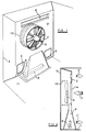
- FIGs. 1 and 2 of the drawings there is shown the rear part of an oven cavity of a gas combination microwave oven, this consisting of a floor section 1 from the rear edge of which extends upwardly a rear wall 2. Spaced from the rear wall 2 is the rear casing 3 of the microwave oven.
- a circular vent 4 behind which is disposed a fan 5 which draws air from the oven cavity through the vent 4, as depicted by the arrow 7 in Fig. 2, into the space between the rear wall 2 and the rear casing 3, and which re-introduces the air into the oven cavity via three peripherally positioned air vents 6, as depicted by the arrows 7′ in Fig. 2.
- the circular vent 4 and the air vents 6 will be formed as a series of small holes, the size of which is chosen so that they afford a block to microwave radiation, thereby protecting the fan 5 and other components located behind the rear wall 2.
- a gas burner 8 which is provided with a chimney 9, formed in part by the rear wall 2, which directs products of combustion from the gas burner to the vicinity of the fan 5, by means of which they are included in the circulated air stream.
- microwave energy source which would normally be associated with the oven cavity is not shown.
- an electrical "booster" coiled heating element 10 is provided, disposed around the periphery of the fan 5 and in the path of the circulating air.
- the gas burner 8 is ignited and the electrical heating element 10 is energised, but not the microwave energy source. With both sources of convection heat operating, the oven warm-up time is substantially reduced, typically to approximately 5 or 6 minutes. When the required oven temperature is reached, the electrical heating element 10 is de-energised and the microwave energy source is energised. The oven then operates as a conventional gas combination microwave oven.
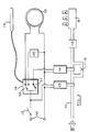
- the gas burner 8 is shown which is supplied with gas G via a gas rail 11 which includes a flame failure device 12 of known form.
- the gas rail 11 is provided with a main, solenoid operated ON/OFF valve 13 for controlling gas flow to the burner 8, and also a further solenoid operated valve 14 which is provided with a by-pass restriction 15 whereby the gas flow to the gas burner 8 can be controlled between full on and a minimum flow rate determined by the restriction 15 which is sufficient to maintain the gas burner alight.
- the solenoid valves 13 and 14 are operated from an alternating current supply (not shown) connected to input terminals 16 of the control system, via an ON/OFF switch 17.
- the main solenoid valve 13 is connected directly to the switch 17 whereas the solenoid valve 14 is connected to the switch 17 via twin switched thermostat 18 which is provided with a heat sensitive phial 19 which is positioned at some suitable position in the oven cavity of the gas combination microwave oven of Fig. 1.
- the twin switched thermostat 18 may be of adjustable form and is provided with a normally closed switch S1 which connects the solenoid valve 14 to the ON/OFF switch 17, and also a changeover switch S2 which normally connects the "booster" heating element 10 to the ON/OFF switch 17, but which in the switched condition of the thermostat 18 connects the microwave energy source 20 to the ON/OFF switch 17. It is arranged within the thermostat 18 that the switch S2 actuates at a lower temperature e.g. by 20°C than the switch S1. Thus, typically, switch S2 may have a range of 0 to 230°C and switch S1 may have a range of 0 to 250°C.
- solenoid valve 13 When the ON/OFF switch is closed, solenoid valve 13 will open and also solenoid valve 14 will open due to the normally closed switch Sl, so that the gas is supplied to the gas burner 8. At the same time the "booster" heating element 10 is connected to the ON/OFF switch 17 via the switch S2. Thus the oven cavity will be heated by the gas burner 8 and by the "booster" heater element 10.
- the switch S2 of the thermostat 18 operates to disconnect the "booster" heater element 10 from the ON/OFF switch 17 and to connect the microwave energy source 20 to the ON/OFF switch 17.
- the oven cavity continues to be heated by the gas burner 8 until the required oven temperature is reached, at which time the switch S1 of the thermostat 18 is operated to cause the solenoid valve 14 to close to restrict the gas flow to the burner 8 to that defined by the by-pass restriction 15.
- the oven then operates as a conventional gas combination microwave oven, the gas burner 8 being operated if the oven cavity temperature falls appreciably. It will be appreciated, however, that during the warm-up period of the oven, both the gas burner 8 and the "booster" heater element 10 are energised, thereby substantially reducing the warm-up time.
- the feature of providing a "booster” heating element may also be used in conventional gas or electric cooking ovens, in order to reduce the warm-up time.
- an electrical "booster” heating element may be provided to reduce the warm-up time
- a gas burner "booster” may be provided for reducing the warm-up time.
Landscapes
- Engineering & Computer Science (AREA)
- Chemical & Material Sciences (AREA)
- Combustion & Propulsion (AREA)
- Mechanical Engineering (AREA)
- General Engineering & Computer Science (AREA)
- Physics & Mathematics (AREA)
- Electromagnetism (AREA)
- Control Of High-Frequency Heating Circuits (AREA)
- Cookers (AREA)
Applications Claiming Priority (2)
| Application Number | Priority Date | Filing Date | Title |
|---|---|---|---|
| GB888815381A GB8815381D0 (en) | 1988-06-28 | 1988-06-28 | Cooking ovens |
| GB8815381 | 1988-06-28 |
Publications (2)
| Publication Number | Publication Date |
|---|---|
| EP0349213A2 true EP0349213A2 (de) | 1990-01-03 |
| EP0349213A3 EP0349213A3 (de) | 1990-10-31 |
Family
ID=10639509
Family Applications (1)
| Application Number | Title | Priority Date | Filing Date |
|---|---|---|---|
| EP19890306384 Withdrawn EP0349213A3 (de) | 1988-06-28 | 1989-06-23 | Kochherde |
Country Status (3)
| Country | Link |
|---|---|
| US (1) | US4926837A (de) |
| EP (1) | EP0349213A3 (de) |
| GB (2) | GB8815381D0 (de) |
Cited By (3)
| Publication number | Priority date | Publication date | Assignee | Title |
|---|---|---|---|---|
| EP0698768A1 (de) | 1994-06-22 | 1996-02-28 | ZANUSSI GRANDI IMPIANTI S.p.A. | Kombinierter Gas- und Mikrowellenkochherd mit Vorrichtung zum Kochen mit Dampf |
| FR2758385A1 (fr) * | 1997-01-10 | 1998-07-17 | Eurofours Sa | Four bi-energie fonctionnant au gaz ou au fioul et a l'electricite et procede de chauffage de l'enceinte d'un tel four |
| ITPD20100003A1 (it) * | 2010-01-14 | 2011-07-15 | Unox Spa | Forno di cottura per alimenti, in particolare per servizi di collettività |
Families Citing this family (29)
| Publication number | Priority date | Publication date | Assignee | Title |
|---|---|---|---|---|
| US5166487A (en) * | 1989-12-15 | 1992-11-24 | Tecogen, Inc. | Cooking oven with convection and microwave heating |
| FR2701090B1 (fr) * | 1993-01-29 | 1995-04-07 | Bourgeois Ste Coop Prod | Four à vapeur à chauffage direct au gaz. |
| US5497760A (en) * | 1994-10-17 | 1996-03-12 | G. S. Blodgett Corporation | Convection oven with power induced back draft flow |
| US6417493B1 (en) | 1999-09-13 | 2002-07-09 | Maytag Corporation | Self-cleaning method for a cooking appliance |
| US6316749B1 (en) | 2000-08-29 | 2001-11-13 | Maytag Corporation | Self-cleaning system for a cooking appliance |
| US6371104B1 (en) | 2000-07-21 | 2002-04-16 | Wayne/Scott Fetzer Company | Convection oven with gas burner |
| US6872919B2 (en) * | 2000-08-29 | 2005-03-29 | Maytag Corporation | Multi-stage catalyst for a cooking appliance |
| FR2839546B1 (fr) * | 2002-05-07 | 2006-09-22 | Premark Feg Llc | Four pour la cuisson d'aliments |
| US6943324B2 (en) * | 2003-04-10 | 2005-09-13 | Maytag Corporation | Combination heating system for a cooking appliance |
| US20050103322A1 (en) * | 2003-11-14 | 2005-05-19 | Smith Robert L. | Dual flow convection oven |
| CA2648480C (en) * | 2005-04-05 | 2014-01-14 | Cropley Holdings Ltd. | Household appliances which utilize an electrolyzer and electrolyzer that may be used therein |
| AU2006243710B2 (en) * | 2006-05-01 | 2012-07-26 | Gbd Corp. | Method and apparatus for cooking using a combustible gas produced with an electrolyzer |
| US8803040B2 (en) * | 2008-09-15 | 2014-08-12 | General Electric Company | Load shedding for surface heating units on electromechanically controlled cooking appliances |
| US8627689B2 (en) * | 2008-09-15 | 2014-01-14 | General Electric Company | Energy management of clothes washer appliance |
| US8843242B2 (en) * | 2008-09-15 | 2014-09-23 | General Electric Company | System and method for minimizing consumer impact during demand responses |
| US9303878B2 (en) * | 2008-09-15 | 2016-04-05 | General Electric Company | Hybrid range and method of use thereof |
| DE102009009867A1 (de) * | 2009-02-20 | 2010-08-26 | Krones Ag | Preformheizung |
| US9534794B2 (en) | 2009-03-16 | 2017-01-03 | Whirlpool Corporation | Convection cooking appliance with circular air flow system |
| US8943857B2 (en) * | 2009-09-15 | 2015-02-03 | General Electric Company | Clothes washer demand response by duty cycling the heater and/or the mechanical action |
| US8943845B2 (en) | 2009-09-15 | 2015-02-03 | General Electric Company | Window air conditioner demand supply management response |
| US8869569B2 (en) * | 2009-09-15 | 2014-10-28 | General Electric Company | Clothes washer demand response with at least one additional spin cycle |
| US8801862B2 (en) | 2010-09-27 | 2014-08-12 | General Electric Company | Dishwasher auto hot start and DSM |
| US9335054B2 (en) * | 2012-08-15 | 2016-05-10 | Whirlpool Corporation | Gas oven with electric and gas heating elements |
| KR101428870B1 (ko) * | 2012-11-27 | 2014-08-14 | 엘지전자 주식회사 | 가스 오븐 레인지 |
| US10009965B2 (en) | 2015-01-28 | 2018-06-26 | Samsung Electronics Co., Ltd. | Gas detection apparatus, cooking apparatus, and method of controlling the apparatuses |
| US10051995B2 (en) * | 2015-09-18 | 2018-08-21 | 7794754 Canada Inc. | Atmospheric rotisserie burner with convection heating |
| EP3627053B1 (de) * | 2018-05-15 | 2026-02-25 | Gas Technology Institute | Verfahren zum betrieb eines konvektionsofen und hocheffizienter konvektionsofen |
| US11739947B2 (en) * | 2020-11-12 | 2023-08-29 | Haier Us Appliance Solutions, Inc. | Oven appliance with convection bake and broil |
| US12031727B2 (en) * | 2021-03-05 | 2024-07-09 | Electrolux Home Products, Inc. | Oven bake heating channel exchange system |
Family Cites Families (8)
| Publication number | Priority date | Publication date | Assignee | Title |
|---|---|---|---|---|
| US31637A (en) * | 1861-03-05 | Improvement in corn-h uskers | ||
| USRE31637E (en) | 1977-05-13 | 1984-07-31 | Sanyo Electric Co., Ltd. | Combination microwave and gas oven |
| DE2751483C2 (de) * | 1977-11-18 | 1983-03-03 | Licentia Patent-Verwaltungs-Gmbh, 6000 Frankfurt | Elektrisch beheizter Bratofen mit Unter- und Oberbeheizung und mit integrierter Mikrowellenheizeinrichtung |
| US4283614A (en) * | 1978-02-20 | 1981-08-11 | Matsushita Electric Industrial Co., Ltd. | Cooking device with high-frequency heating means and resistance heating means |
| JPS5832083Y2 (ja) * | 1978-07-31 | 1983-07-16 | 三洋電機株式会社 | ガス複合調理装置 |
| CA1138049A (en) * | 1979-01-16 | 1982-12-21 | William J. Day | Self-cleaning microwave convection oven |
| JPS5832084Y2 (ja) * | 1979-01-25 | 1983-07-16 | リンナイ株式会社 | 加熱調理器 |
| GB2105459B (en) * | 1981-09-05 | 1984-11-21 | Cannon Ind Ltd | Dual function cooking oven |
-
1988
- 1988-06-28 GB GB888815381A patent/GB8815381D0/en active Pending
-
1989
- 1989-06-23 EP EP19890306384 patent/EP0349213A3/de not_active Withdrawn
- 1989-06-23 GB GB8914430A patent/GB2220740B/en not_active Expired - Fee Related
- 1989-06-27 US US07/371,793 patent/US4926837A/en not_active Expired - Fee Related
Cited By (4)
| Publication number | Priority date | Publication date | Assignee | Title |
|---|---|---|---|---|
| EP0698768A1 (de) | 1994-06-22 | 1996-02-28 | ZANUSSI GRANDI IMPIANTI S.p.A. | Kombinierter Gas- und Mikrowellenkochherd mit Vorrichtung zum Kochen mit Dampf |
| US5556566A (en) * | 1994-06-22 | 1996-09-17 | Zanussi Grandi Impianti S.P.A. | Combined gas-microwave cooking oven with steam operation |
| FR2758385A1 (fr) * | 1997-01-10 | 1998-07-17 | Eurofours Sa | Four bi-energie fonctionnant au gaz ou au fioul et a l'electricite et procede de chauffage de l'enceinte d'un tel four |
| ITPD20100003A1 (it) * | 2010-01-14 | 2011-07-15 | Unox Spa | Forno di cottura per alimenti, in particolare per servizi di collettività |
Also Published As
| Publication number | Publication date |
|---|---|
| GB2220740B (en) | 1992-04-15 |
| US4926837A (en) | 1990-05-22 |
| GB8914430D0 (en) | 1989-08-09 |
| GB8815381D0 (en) | 1988-08-03 |
| GB2220740A (en) | 1990-01-17 |
| EP0349213A3 (de) | 1990-10-31 |
Similar Documents
| Publication | Publication Date | Title |
|---|---|---|
| EP0349213A2 (de) | Kochherde | |
| US6987252B2 (en) | Speedcooking oven including convection/bake mode and microwave heating | |
| JP6934341B2 (ja) | 加熱調理器 | |
| US3899656A (en) | Self-cleaning oven with temperature limiting protection system for bake and clean | |
| US3619564A (en) | Self-cleaning oven with temperature limiting protection system | |
| US5197112A (en) | Fixed volume PTC air heater with heat output adjusted by a damper controlling air flow over the PTC element | |
| US3686476A (en) | Oven with temperature limiting protection and indicating system | |
| GB2258126A (en) | Cooling and ventilating oven heated with micrwaves and other means | |
| US3794460A (en) | Control arrangement for air ventilating and air heating systems having automatic reset and manual reset safety devices | |
| GB2292630A (en) | Ignition system for gaseous fuel burner assemblies | |
| JPH0144917Y2 (de) | ||
| GB2198520A (en) | Gas oven | |
| KR910017129A (ko) | 가열 조리기 | |
| JPH03123520A (ja) | 暖房装置 | |
| JPH0455621A (ja) | 加熱調理器 | |
| JP2002303425A (ja) | オーブン兼暖房装置 | |
| JPH0225103B2 (de) | ||
| JP3621281B2 (ja) | 液体燃焼器における燃料供給装置 | |
| KR930003606Y1 (ko) | 전기 기기의 오동작 방지장치 | |
| US5403182A (en) | Control system for gas fired heating apparatus using double-throw radiant heat sensing switch | |
| JPH0450489B2 (de) | ||
| GB2143943A (en) | Gas-fired appliances | |
| JPH0737041Y2 (ja) | ガス調理器 | |
| JP2589756B2 (ja) | 暖房装置 | |
| JPS62299624A (ja) | 高周波加熱装置 |
Legal Events
| Date | Code | Title | Description |
|---|---|---|---|
| PUAI | Public reference made under article 153(3) epc to a published international application that has entered the european phase |
Free format text: ORIGINAL CODE: 0009012 |
|
| AK | Designated contracting states |
Kind code of ref document: A2 Designated state(s): DE ES FR IT |
|
| PUAL | Search report despatched |
Free format text: ORIGINAL CODE: 0009013 |
|
| AK | Designated contracting states |
Kind code of ref document: A3 Designated state(s): DE ES FR IT |
|
| 17P | Request for examination filed |
Effective date: 19901106 |
|
| 17Q | First examination report despatched |
Effective date: 19910418 |
|
| STAA | Information on the status of an ep patent application or granted ep patent |
Free format text: STATUS: THE APPLICATION IS DEEMED TO BE WITHDRAWN |
|
| 18D | Application deemed to be withdrawn |
Effective date: 19910829 |