EP0349099A2 - Transparente Lastteilung für parallele Netzwerke - Google Patents
Transparente Lastteilung für parallele Netzwerke Download PDFInfo
- Publication number
- EP0349099A2 EP0349099A2 EP89303489A EP89303489A EP0349099A2 EP 0349099 A2 EP0349099 A2 EP 0349099A2 EP 89303489 A EP89303489 A EP 89303489A EP 89303489 A EP89303489 A EP 89303489A EP 0349099 A2 EP0349099 A2 EP 0349099A2
- Authority
- EP
- European Patent Office
- Prior art keywords
- bridge
- networks
- messages
- bridges
- trunked
- Prior art date
- Legal status (The legal status is an assumption and is not a legal conclusion. Google has not performed a legal analysis and makes no representation as to the accuracy of the status listed.)
- Granted
Links
- 238000000034 method Methods 0.000 claims abstract description 53
- 230000027455 binding Effects 0.000 claims abstract description 26
- 238000009739 binding Methods 0.000 claims abstract description 26
- 238000004891 communication Methods 0.000 claims abstract description 15
- 230000006854 communication Effects 0.000 claims abstract description 15
- 230000000875 corresponding effect Effects 0.000 claims description 32
- 230000015654 memory Effects 0.000 claims description 19
- 238000012544 monitoring process Methods 0.000 claims 1
- 230000004044 response Effects 0.000 claims 1
- 238000010586 diagram Methods 0.000 description 27
- 238000012545 processing Methods 0.000 description 10
- 208000027744 congestion Diseases 0.000 description 8
- 230000008569 process Effects 0.000 description 8
- 230000003936 working memory Effects 0.000 description 8
- 230000005540 biological transmission Effects 0.000 description 4
- 238000013461 design Methods 0.000 description 3
- 238000007726 management method Methods 0.000 description 3
- 238000001514 detection method Methods 0.000 description 2
- 238000011156 evaluation Methods 0.000 description 2
- 230000008859 change Effects 0.000 description 1
- 229910052729 chemical element Inorganic materials 0.000 description 1
- 238000010276 construction Methods 0.000 description 1
- 230000008094 contradictory effect Effects 0.000 description 1
- 230000006870 function Effects 0.000 description 1
- 230000006872 improvement Effects 0.000 description 1
- 230000014759 maintenance of location Effects 0.000 description 1
- 230000007246 mechanism Effects 0.000 description 1
- 238000012986 modification Methods 0.000 description 1
- 230000004048 modification Effects 0.000 description 1
- 230000008520 organization Effects 0.000 description 1
- 230000008521 reorganization Effects 0.000 description 1
- 238000003860 storage Methods 0.000 description 1
Images


Classifications
-
- H—ELECTRICITY
- H04—ELECTRIC COMMUNICATION TECHNIQUE
- H04L—TRANSMISSION OF DIGITAL INFORMATION, e.g. TELEGRAPHIC COMMUNICATION
- H04L45/00—Routing or path finding of packets in data switching networks
- H04L45/74—Address processing for routing
- H04L45/742—Route cache; Operation thereof
-
- H—ELECTRICITY
- H04—ELECTRIC COMMUNICATION TECHNIQUE
- H04L—TRANSMISSION OF DIGITAL INFORMATION, e.g. TELEGRAPHIC COMMUNICATION
- H04L12/00—Data switching networks
- H04L12/28—Data switching networks characterised by path configuration, e.g. LAN [Local Area Networks] or WAN [Wide Area Networks]
- H04L12/46—Interconnection of networks
- H04L12/4604—LAN interconnection over a backbone network, e.g. Internet, Frame Relay
- H04L12/462—LAN interconnection over a bridge based backbone
-
- H—ELECTRICITY
- H04—ELECTRIC COMMUNICATION TECHNIQUE
- H04L—TRANSMISSION OF DIGITAL INFORMATION, e.g. TELEGRAPHIC COMMUNICATION
- H04L45/00—Routing or path finding of packets in data switching networks
- H04L45/02—Topology update or discovery
- H04L45/04—Interdomain routing, e.g. hierarchical routing
-
- H—ELECTRICITY
- H04—ELECTRIC COMMUNICATION TECHNIQUE
- H04L—TRANSMISSION OF DIGITAL INFORMATION, e.g. TELEGRAPHIC COMMUNICATION
- H04L45/00—Routing or path finding of packets in data switching networks
- H04L45/24—Multipath
Definitions
- the present invention relates to the field of network management in general and specifically to the improvement of communications in a local area network containing a number of bridges.
- Networks are used to interconnect sources and receivers of data.
- the nature of the data sources and receivers is not important, and all of such sources and receivers will be called "end nodes.”
- Networks provide a capability for end nodes to send messages to each other.
- a basic type of network is called a local area network or LAN.
- a LAN contains end nodes and some means for transmission between the end nodes, such as one or more wires interconnecting the nodes.
- messages between end nodes need only include a source identifier, a destination identifier, data to be transmitted, and other desired “overhead” such as network management information or error detection codes.
- networks such as LANS need to be interconnected. Such interconnection could occur if a network was to be extended or connected to dissimilar networks. Interconnection of the networks can involve the creation of a higher level network or, as long as the interconnection is not too extensive, the joining of networks at the same level.
- Routers If a higher level network is created, certain devices called “routers” must be used. Routers, however, add another layer of communication protocol and end node messages must include information to reflect the added protocol.
- bridges are used to join the networks. With bridges, the end node messages need not contain additional protocol information. Ideally, bridges should be transparent to end nodes so that interconnected networks appear as one large network.
- IEEE 802.1 Media Access Control Bridge Standard (Rev. E) (hereinafter "IEEE standard"), which is incorporated herein by reference, has decided that transparent bridges are to be standard for all IEEE 802 local area networks.
- the bridges develop their data bases by also examining the source addresses of the messages received.
- a bridge reversiblyceives a message from one network, it determines that, barring other circumstances such as contradictory information, the end node specified in the source identifier may be reached via the network from which the message is received.
- the network from which the message was received is called the "station address" for the source end node, and the data base is a collection of end nodes and corresponding station addresses.
- the station address for an end node does not indicate that the corresponding end node is on the network specified by the station address. For example, a message may have been received from a source end node on a different network, and the message may have been forwarded to the station address network by another bridge.
- the station address only indicates that the identified end node may be reached in the direction of the network from which the message was received.
- bridged networks generally work quite well, their operation breaks down if there is some sort of a loop.
- a loop exists when two networks are connected by more than one bridge.
- Loops occur either accidentally, for example because of poor bridge design, or can sometimes be designed into a network topology to provide either redundancy or backup.
- one of the bridges sends a message from a first network to a second network. That first bridge then records in its data base that the station address for the source of the message is the first network.
- the second bridge receives that forwarded message on the second network, the second bridge determines that the station address of source for the message is the second network. The second bridge then forwards the message back to the first bridge. This forwarding process will continue indefinitely without some sort of safeguard.
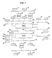
- Fig. 1 illustrates how loops occur in interconnected networks.
- Fig. 1 shows networks 110, 120, 130, 140, 150, 160, 170, 180, 183, 186, 190, and 196.
- End nodes 111 and 112 are connected to network 110; end nodes 121 and 122 are connected to network 120; end nodes 131 and 132 are connected to network 130; end nodes 141 and 142 are connected to network 140; end nodes 151 and 152 are connected to network 150; end node 161 is connected to network 160; end node 171 is connected to network 170; end node 181 is connected to network 180; end node 184 is connected to network 183; end node 187 is connected to network 186; and end node 191 is connected to network 190.
- Bridges 115, 125, 135, 145, and 155 interconnect the different networks.
- Bridges 115 and 125 interconnect networks 110 and 120; bridge 135 interconnects networks 130 and 140; bridge 145 interconnects networks 120, 150, 160, 180, 190, and 196; and bridge 155 interconnects networks 130, 170, 183, 186, 190, and 196.
- a mechanism must be devised either to resolve the loops or to avoid them.
- One method which has been devised and is described in detail in both the Backes article and the IEEE standard is the spanning tree algorithm. Generally, this algorithm involves ordering the bridges according to some criterion. Then, one bridge connected to each network is chosen as a designated bridge according to the ordering criterion, and only the designated bridge can forward messages to and from the network for which it is a designated bridge. Use of this algorithm thus breaks any loops. The other bridges connected to a network are called daughter bridges, and they forward messages to the designated bridge on only one network.
- the spanning tree algorithm in this form creates an additional problem. If messages are forwarded on only one of the trunked networks, congestion may result.
- One way to relieve the congestion in networks created by the spanning tree algorithm is to distribute messages from daughter bridges to designated bridges across all of the common networks in a round-robin, or similar algorithm.
- the problem with this method is that it does not preserve the time sequence of messages.
- Time sequence of messages refers to the order in which messages are sent from one end node to another end node. Time sequence is important because the data sent between end nodes may be spread across several messages. If the messages are received out of order, the data may be garbled. When using the round-robin algorithm, the time sequence of messages cannot be guaranteed because messages may have different sizes and be transmitted at different rates which could disrupt the order of their transmission.
- the present invention overcomes the problems of network topology by locating "trunked” networks and distributing messages among those trunked networks without creating loops and maintaining the time sequence of the messages.
- the method of this invention is for improving communication among end nodes in a collection of networks connected to a plurality of end nodes and to at least one of a plurality of bridges used to forward messages in a time sequence between the end nodes.
- the method comprises the step of selecting one of the bridges connected to each network as a designated bridge for that network to forward messages to and from that network.
- the remaining bridges connected to that network which are not selected as a designated bridge are deemed daughter bridges.
- Another step according to the method of this invention is sensing, by each of the daughter bridges, whether a trunking condition exists for the ones of the networks connected to that daughter bridge.
- the trunking condition occurs when a plurality of networks, termed trunked networks, are connected to that daughter bridge and to a corresponding one of the designated bridges.
- the daughter bridges which sense the trunking condition are termed trunked daughter bridges.
- the method of this invention also includes the step of executing a binding scheme by a selected one of the trunked daughter bridges.
- the execution of the binding scheme causes a selected trunked daughter bridge to act as a plurality of daughter bridges each connected to a different one of the trunked networks corresponding to that selected trunked daughter bridge. This operation distributes the messages sent from the selected trunked daughter bridge and to the corresponding designated bridge among the connected trunked networks in a matter which preserves the time sequence of the messages.
- the method of this invention can be performed with the elements of the network shown in Fig. 1 if they are properly configured.
- a collection of networks, 110, 120, 130, 140, 150, 160, 170, 180, 183, 186, 190, and 196 are connected to a plurality of end nodes 111, 112, 121, 122, 131, 132, 141, 142, 151, 152, 161, 171, 181, 184, 187, and 191.
- Each of the networks is also connected to at least one of the bridges 115, 125, 135, 145, and 155. In accordance with the present invention, those bridges forward messages between the end nodes in a particular time sequence, as described above.
- Fig. 2 shows a general flow diagram 200 for a preferred process in accordance with the method of this invention for improving communication among end nodes.
- one of the bridges connected to each of the networks is selected as a designated bridge for that network to forward messages to and from that network.
- the remaining bridges connected to that network which are not selected as a designated bridge are deemed to be daughter bridges.
- Flow diagram 200 contains several steps for providing such a selection process according to the spanning tree algorithm.
- the present invention is not necessarily limited to the use of a spanning tree algorithm, although use of the spanning tree algorithm is preferred.
- the spanning tree algorithm requires at a minimum that each bridge have a unique bridge identifier throughout the networks to which the algorithm is applied, and that the ports within each bridge, which are where the bridges connect to the networks, each have a unique identifier within the corresponding bridge.
- configuration messages exchanged by the bridges must have addresses which all bridges will receive. Otherwise, the communication among the bridges would become difficult, if not impossible.
- Bridge 300 which has a unique identifier, also has ports 310, 320 and 330, each of which are uniquely identified in bridge 300. Bridge ports 310, 320 and 330 are connected respectively to networks 315, 325 and 335.
- Bridge 300 also includes a bridge processing unit 340 which is preferably a commercially available microprocessor, but can also be a specially designed unit.
- bridge processing unit 340 is preferably a commercially available microprocessor, but can also be a specially designed unit.
- the only important feature of bridge processing unit 340 is that it contain sufficient circuitry and capability to perform the logic operations described below.
- Bridge processing unit 340 can also contain the capabilitiesity to perform other operations, such as bridge performance evaluation, which are not part of the present invention.
- Bridge 300 preferably includes a bridge memory unit 350 which has three portions: program memory 360, working memory 370, and bridge forwarding data base 380.
- Program memory 360 contains various sequences of instructions which cause bridge processing unit 340 to perform necessary and desired operations.
- Program memory 360 can either be a ROM, PROM or a RAM, depending upon the design considerations and expected use of program memory 360.
- Bridge memory unit 350 also includes a working memory 370, which is preferably a RAM.
- working memory 370 is to construct messages and to provide a means for temporary storage, such as when executing the spanning tree algorithm.
- bridge forwarding data base 380 includes a RAM or a set of registers.
- data base 380 contains a representation of the topology of the collection of end nodes as seen by bridge 300.
- bridge 300 When bridge 300 receives a message it consults data base 380 to find the proper port ( i.e. , network) to use for forwarding the message.
- Bridge 300 could be constructed from a Translan III bridges manufactured by the Vitalink Communications Corporation, which would then need to be configured and programmed to perform the method of the present invention.
- the first step in flow diagram 200 which is also part of the spanning tree algorithm, is for the bridges to exchange configuration messages, called "hello" messages or bridge protocol data units (BPDUs) with the other bridges (step 210).
- BPDUs bridge protocol data units
- Such periods are adjustable but can occur, for example, every four (4) seconds.
- the exchange occurs during repeating configuration periods.
- BPDUs are sent between bridges.
- each BPDU include several fields shown in Fig. 4 as overhead field 410, root identifier field 420, root path cost field 430, bridge identifier field 440, and port identifier field 450.
- Overhead field 410 includes several portions not relevant to the present invention. For example, overhead field 410 could include indicators of the BPDU type, or certain flags, such as signals of a topology change if a bridge is reconnected. Overhead field 410 could also identify a protocol version or standard, or could include timing, delay or performance information to allow for proper bridge management. A more detailed explanation of such overhead fields may be found in the IEEE standard.
- Root identifier field 420 identifies the bridge believed to be the root by the transmitting bridge.
- the root bridge is a bridge chosen by the other bridges to help in organizing the spanning tree.
- Root path cost field 430 contains an indicator of the "costs" of the path from the root bridge to the transmitting bridge.
- the root path cost is often calculated by tallying values for the networks through which a message must pass between the root bridge and the transmitting bridge.
- One way of determining root path costs is for a bridge to receive a BPDU from a bridge closer to the root, add to the root path cost in that BPDU a stored value representing the "cost" of the network from which that BPDU was received. The sum is the root path cost for the BPDUs which the bridge then transmits.
- each bridge has stored values for network costs in memory 350, and those stored values correspond to the ports through which messages are received.
- Bridge identifier field 440 contains the unique bridge identifier described above.
- Port identifier field 450 contains the unique identifer of the port of the transmitting bridge through which BPDU 400 was transmitted.
- the next step in flow diagram 200 is also part of the spanning three algorithm and involves choosing the root bridge (step 220).
- the root bridge is important in the spanning tree algorithm so that designated bridges may be selected.
- One way to chose the root bridge is to have the unique bridge identifiers include a priority field and an additional field which preserves uniqueness in cases of shared priority.
- the priority can be set in a number of ways to reflect design or operational concerns.
- the root bridge would be the bridge with the best priority. If more than one bridge has the best priority, then the additional field is used.
- the selection of the root bridge would be done by the bridges themselves using bridge processor 340 under control of program memory 360 and with the aid of working memory 370.
- a preferred method of selection calls for each bridge to compare the root identifier field 420 of the BDPUs it receives to a stored root identifier. If the received message has a root identifier field with a better priority than the stored root identifier, the root identifier value in the received message would become the new stored root identifier. With this method, all bridges will eventually have the same stored root identifier.
- the next step is to evaluate the BPDUs from the other bridges to choose a designated bridge and daughter bridges for each network (step 230). This too is part of the spanning tree algorithm. In the preferred embodiment of this invention, such evaluation is done by each bridge using the appropriate bridge processing unit 340 under control of program memory 360 and working memory 370.
- all bridges connected to the same network compare root path costs, which are concurrently being determined in a manner described above.
- the bridge with the lowest root path cost is deemed to be the designated bridge for that network. If multiple bridges have the same root path cost, then some technique, such as use of the bridge identifier is used to select the designated bridge. All of the bridges connected to a network which do not have another path to the root,and are not selected to be a designated bridge are deemed to be daughter bridges.
- this selecting step involves exchanging configuration messages, such as BPDUs, among the bridges during the repeating configuration periods, as described with regard to step 210.
- each of the daughter bridges senses whether a trunking condition exists for the networks which are connected to that daughter bridge.
- the trunking condition occurs when a plurality of networks, termed trunked networks, are connected both to a particular daughter bridge and to a corresponding designated bridge for those same networks.
- networks 190 and 196 are trunked networks.
- the daughter bridges sensing the trunking condition are termed "trunked daughter bridges.”
- the existence of trunking condition is determined by detecting the existence of parallel networks between a designated and a trunked daughter bridge for that network (step 240).
- Flow diagram 500 in Fig. 5 shows specific steps in the preferred implementation of this method for determining the existence of a trunking condition.
- each of the daughter bridges performs the steps shown in flow diagram 500 with bridge processing unit 340 under the control of the program memory 360 and using working memory 370.
- the first step in flow diagram 500 is the initialization by each daughter bridge of its BPDU information at the beginning of a configuration period (step 510). This allows a complete procedure to take place each configuration period.
- the method of improving communication among end nodes includes the comparison of the BPDUs received by each of the daughter bridges to find occurrences of multiple configuration messages received during the same configuration period, which messages differ only in the port identifier portion.
- the configuration messages should include a port identification portion specifying a code for the port from which the corresponding message is transferred.
- this step is carried out by including port identifiers in the BPDUs, as Fig. 4 shows with identifier 450 in BPDU 400.
- the occurrences of such multiple configuration messages indicates the existence of a trunking condition because receipt of such messages shows that the message traveled from the same source through parallel networks.
- such comparison is preferably carried out in several steps. First, the BPDU for the next port is examined (step 520). Next, a comparison is made between that BPDU and the other BPDUs which had been previously examined (step 530).
- the daughter bridge records the occurrence of a trunking condition and groups into the same "trunking group" those ports which received the BPDUs that differ only in the port identifiers (step 540). This procedure is continued for all BPDUs and all the ports (step 550). Preferably, the entire procedure in Fig. 5 is repeated each configuration period.
- Also in accordance with the present invention of a method for improving communication among end nodes is the step of executing a binding scheme by a selected one the trunked daughter bridges.
- the binding scheme causes that trunked daughter bridge to act as a plurality of daughter bridges each of which is connected to a different one of the trunked networks corresponding to that selected trunk daughter bridge.
- messages forwarded between the selected trunked daughter bridge and the corresponding designated bridge are distributed among the connected trunked networks in a matter which also preserves the time sequence of the messages.
- Each of the trunked daughter bridges can also execute its own binding scheme, as indicated in step 250 of the flow diagram 200 in Fig. 2.
- flow diagram 600 A more detailed explanation of the substeps for executing the binding scheme is shown in flow diagram 600 in Fig. 6. Although the operations in flow diagram 600 are described for a single daughter bridge, those operations would preferably be performed for all of the trunked daughter bridges.
- executing the binding scheme could involve first organizing the selected trunked daughter bridge into a first number, e.g. , N, of forwarding groups, where N is equal to the number of networks in the corresponding set of trunked networks.
- N is equal to the number of networks in the corresponding set of trunked networks.
- Fig. 7 shows a daughter bridge 700 connected to five trunked networks 710, 720, 730, 740 and 750.
- the forwarding groups are shown as 715, 725, 735, 745 and 755.
- the daughter bridge first determines the number of trunked networks (step 610).
- the bridge would execute the steps in flow chart 600 using a bridge processing unit 340 under control of program memory 360, and might also make use of working memory 370.
- the next substep in executing a binding scheme is collecting the ones of the networks, termed “nontrunked networks,” which are connected to the selected trunked daughter bridge but which are not in the set of corresponding trunked networks, into the first number of substantially equal-size, nonoverlapping subsets of nontrunked networks.
- An important step in such collection is the selected daughter bridge's organization of the nontrunked networks into N nonoverlapping subsets (step 620).
- daughter bridge 700 were connected to the five trunked networks 710, 720, 730, 740, 750, as well as ten nontrunked networks 712, 714, 722, 724, 732, 734, 742, 744 and 752 and 754, the nontrunked networks would be organized into five subsets of two nontrunked networks each.
- the last substep of executing the binding scheme in accordance with one method of the present invention is to associate each of the forwarding groups with a different one of the corresponding trunked networks and a different one of the nonoverlapping subsets of nontrunked networks.
- the daughter bridge would form N forwarding groups each comprising one trunked network and one or more nontrunked networks (step 630).
- the purpose of the forwarding groups is to allow the daughter bridge to forward messages to the designated brige as if each of the forwarding groups were a separate daughter bridge. This avoids the problem of congestion when all of the messages are transferred down one of the trunked networks and, as will become clearer below, preserves transmission of the messages being in the original time sequence.
- daughter bridge 700 using bridge processing unit 340 under control of program memory 360 and with memory 370, forms forwarding groups 715, 725, 735, 745, and 755 such that: forwarding group 715 includes trunked network 710 and nontrunked networks 712 and 714; forwarding group 725 includes trunked network 720 and nontrunked networks 722 and 724; forwarding group 735 includes trunked network 730 and nontrunked networks 732 and 734; forwarding group 745 includes trunked network 740 and nontrunked networks 742 and 744; and forwarding group 755 includes trunked network 750 and nontrunked networks 752 and 754.
- each forwarding group with a different trunked network and nonoverlapping subset of nontrunked networks can include other steps.
- One such step involves some initial correspondence between the end nodes connected to each subset of nontrunked networks and the trunked networks associated with the same forwarding group as that subset. This step assists in the message or frame forwarding operations carried out by the bridge.
- Preferably such correspondence involves use of a table, shown below, in forwarding data base 380 which can be set up either automatically or manually.
- Fig. 8 shows a format of a message 800 which is typical of the messages sent between end nodes on a networks or a set of networks as shown in Fig. 1.
- Message 800 includes a destination identifier 810, a source identifier 820, data 830, an error detection code 840, and overhead 850.
- Each bridge examines the destination identifier 810 of message 800 to decide whether to forward or discard the message. Preferably, the bridge makes this determination after consulting forwarding data base 380.
- Fig. 9 shows an example of forwarding data base 380.
- data base 380 includes an end node list 910 and a port identifer list 920.
- End node list 910 contains unique identifiers for each end node about which the particular bridge is aware.
- Port identifier list 920 indicates the port, and therefore the network, to which any messages for the corresponding end node in list 910 should be forwarded.
- each time a bridge receives a message it consults forwarding data base 380 using the bridge processing unit 340 and the program memory 360. If the bridge matches the destination identifier field 810 with an entry in end node list 910, the message is forwarded out the port identified in the corresponding entry in port identifier list 920. If no match was found, the bridge forwards the message to all networks in the forwarding group except for the network on which the message was received.
- the binding scheme just described not only relieves congestions, but maintains a loop avoidance of the spanning tree algorithm.
- the binding scheme relieves congestion because communications between one of the daughter bridges and the corresponding designated bridges will now occur along each of the trunked networks.
- all of the messages into the daughter bridge would be forwarded to the designated bridge over only a single trunked network.
- the messages from the nontrunked networks will be forwarded to the designated bridge over the trunked network which is in the same forwarding group as the nontrunked network from which the message was received.
- Loops are still avoided because messages sent from the designated bridge to the daughter bridge on a trunked network are never forwarded to another trunked network, or to a nontrunked network which is not part of the forwarding group associated with the trunked network on which the message was received.
- the daughter bridge forwards such messages as though it was N daughter bridges.
- each forwarding group in the daughter bridge shares the same forwarding data base 380, it is assured that each forwarding group has a consistent view of the ports for nontrunked networks through which certain end nodes are reachable.
- the time sequence of the message is maintained because all of the messages from a particular end node which are forwarded by the designated bridge will still proceed over the same trunked networks.
- the only difference which the binding scheme affects is that messages from two different end nodes may not be transmitted over the same network.
- the sequence of messages from different end nodes, however, is not critical to network performance.
- the method is transparent to the end nodes because it takes place entirely within the bridges, so the end nodes need not be aware of the network reorganization.
- the daughter bridge Before the binding scheme was executed, the daughter bridge had a simple forwarding data base. All the end nodes reached through the trunked networks had only one port identifier because the spanning tree algorithm specifies that in trunking conditions, daughter bridges should communicate with the corresponding designated bridges over only one network. After the binding scheme is executed, however, communication will occur over several trunked networks. Therefore, port identifier list 920 must be updated for such entries to reflect the trunked networks for each forwarding group.
- Fig. 10 contains a detailed flow diagram 1000 for carrying out the frame forwarding adjustment.
- such forwarding involves first determining whether a message from any network has a destination address for a group of end nodes, or has an unknown address (step 1010). If so, then the message received by a daughter bridge in a forwarding group is forwarded to all of the networks in that forwarding group (step 1020).
- the next determination is whether the message was received on a trunked network (step 1030).
- the port number associated with the destination identifier in forwarding data base 380 should be checked to see if it was in the same forwarding group as the trunked network on which the message was received (step 1040). If not, then the message would be discarded (step 1080). Otherwise, the message would be forwarded to the port associated with the destination identifier in forwarding data base 380 (step 1070).
- the port associated with the destination identifier in forwarding data base 380 would be checked to see if it was also a nontrunked network (step 1050). If the port associated with the known destination identifier in forwarding data base 380 is for a nontrunked network, and the message was received on a nontrunked network, then the message is forwarded to the port associated with the destination identifier in forwarding data base 380 (step 1070).
- the port associated with the destination identifier in forwarding data base 380 is a trunked network, then that network is checked to see whether it is in the same forwarding group as the port on which the message was received (step 1060). If it is, then the message is forwarded through that trunked network (step 1070). If not, the message is discarded (step 1080).
- Bridge forwarding after execution of the binding scheme is not the same as before execution of the binding scheme. For example, if a message from a nontrunked network is received in a particular forwarding group, and the destination address of that message is unknown, then that message is sent to all of the networks in the particular forwarding group, not to all of the networks in the daughter bridge. This is normally not a problem because the message with the unknown destination identifier will be sent over the trunked network to the designated bridge. The designated bridge will, if it is also unaware of the destination address, send the message back over the other trunked networks and eventually to all of the nontrunked networks which are not in the forwarding group of the nontrunked network originally carrying the message to the daughter bridge.
- Fig. 11 contains a detailed flow diagram 1100 to explain a method of adjusting bridge learning in accordance with this invention.
- the daughter bridge monitors messages forwarded by the corresponding designated bridge.
- the daughter bridge then updates the table to correspond the end nodes with the trunked networks if the addresses of the end nodes were previously unknown.
- the updating preferably involves determining initially whether the message was received on a nontrunked network (step 1110). If not, meaning the message was received on a trunked network, the source identifier is checked to see whether it is contained in forwarding data base 380 (step 1120). If the source identifier is unknown, then forwarding data base 380 is updated with the location of the source identifier (step 1150). Otherwise, no update should occur because the source may have already been learned from a nontrunked network.
- the source identification is checked against the information in forwarding data base 380 to see whether the information is different from that in data base 380, or if the source identification is unknown (step 1140). If either condition is met, then forwarding data base 380 is updated with the location of the source identification (step 1150).
- trunked daughter bridge can update forwarding data base 280 with new information about a previously known or previously unknown end nodes only if that information is ascertained by observing messages received on nontrunked networks. The only information which can be ascertained from trunked networks concerns previously unknown end nodes.
Landscapes
- Engineering & Computer Science (AREA)
- Computer Networks & Wireless Communication (AREA)
- Signal Processing (AREA)
- Small-Scale Networks (AREA)
- Data Exchanges In Wide-Area Networks (AREA)
- Communication Control (AREA)
Applications Claiming Priority (2)
| Application Number | Priority Date | Filing Date | Title |
|---|---|---|---|
| US21235988A | 1988-06-27 | 1988-06-27 | |
| US212359 | 1988-06-27 |
Publications (3)
| Publication Number | Publication Date |
|---|---|
| EP0349099A2 true EP0349099A2 (de) | 1990-01-03 |
| EP0349099A3 EP0349099A3 (de) | 1991-09-18 |
| EP0349099B1 EP0349099B1 (de) | 1995-03-01 |
Family
ID=22790677
Family Applications (1)
| Application Number | Title | Priority Date | Filing Date |
|---|---|---|---|
| EP89303489A Expired - Lifetime EP0349099B1 (de) | 1988-06-27 | 1989-04-10 | Transparente Lastteilung für parallele Netzwerke |
Country Status (5)
| Country | Link |
|---|---|
| EP (1) | EP0349099B1 (de) |
| JP (1) | JPH0244940A (de) |
| AU (1) | AU600408B2 (de) |
| CA (1) | CA1319185C (de) |
| DE (1) | DE68921373T2 (de) |
Cited By (9)
| Publication number | Priority date | Publication date | Assignee | Title |
|---|---|---|---|---|
| US5046065A (en) * | 1988-08-30 | 1991-09-03 | U.S. Philips Corporation | Communication system, a station to be used in such a system, and a gate connecting element to be used in such a system, as well as a device comprising such a gate connecting element |
| EP0926863A3 (de) * | 1997-12-16 | 1999-08-18 | Hewlett-Packard Company | Automatische Konfiguration von Netzverbindungen |
| WO2000018071A1 (en) * | 1998-09-24 | 2000-03-30 | Madge Networks Limited | Communications network bridge |
| EP1162788A3 (de) * | 2000-06-09 | 2002-07-31 | Broadcom Corporation | "Trunking" und "Mirroring" über "stacked gigabit" Vermittlungsstelle |
| EP1768319A1 (de) * | 2005-09-26 | 2007-03-28 | Huawei Technologies Co., Ltd. | Verfahren zur Redundanzbereitstellung in Brücken zwischen RPR-Ringen |
| WO2008110085A1 (en) * | 2007-03-13 | 2008-09-18 | Huawei Technologies Co., Ltd. | Rpr bridge redundancy protection method, rpr bridge ring device and rpr bridge ring |
| WO2008110086A1 (en) * | 2007-03-09 | 2008-09-18 | Huawei Technologies Co., Ltd. | Redundancy protection method and system for bridge mode resilient packet rings |
| CN101136830B (zh) * | 2006-09-01 | 2011-01-12 | 华为技术有限公司 | Rpr桥故障恢复后的环路避免方法 |
| CN101136838B (zh) * | 2006-08-29 | 2012-07-04 | 华为技术有限公司 | 一种桥模式弹性分组环跨环桥设备冗余保护的方法 |
Families Citing this family (1)
| Publication number | Priority date | Publication date | Assignee | Title |
|---|---|---|---|---|
| JP3329841B2 (ja) * | 1991-10-18 | 2002-09-30 | 株式会社日立製作所 | ネットワークシステム及びそのソフトウエア管理方法 |
-
1989
- 1989-04-10 EP EP89303489A patent/EP0349099B1/de not_active Expired - Lifetime
- 1989-04-10 DE DE68921373T patent/DE68921373T2/de not_active Expired - Fee Related
- 1989-04-18 AU AU33120/89A patent/AU600408B2/en not_active Ceased
- 1989-05-31 JP JP1138999A patent/JPH0244940A/ja active Pending
- 1989-06-26 CA CA000603883A patent/CA1319185C/en not_active Expired - Fee Related
Non-Patent Citations (3)
| Title |
|---|
| GLOBAL TELECOMMUNICATIONS CONFERENCE, New Orleans, Louisiana, 2nd - 5th December 1985, pages 34.1.1-34.1.5; K.-B.K. SY et al.: "Source routing for local area network" * |
| IEEE NETWORK, vol. 2, no. 1, January 1988, pages 10-15, New York, US; J. HART: "Extending the IEEE 802.1 MAC bridge standard to remote bridges" * |
| IEEE NETWORK, vol. 2, no. 1, January 1988, pages 5-9; F. BACKES: "Transparent bridges for interconnection of IEEE 802 LANs" * |
Cited By (12)
| Publication number | Priority date | Publication date | Assignee | Title |
|---|---|---|---|---|
| US5046065A (en) * | 1988-08-30 | 1991-09-03 | U.S. Philips Corporation | Communication system, a station to be used in such a system, and a gate connecting element to be used in such a system, as well as a device comprising such a gate connecting element |
| EP0926863A3 (de) * | 1997-12-16 | 1999-08-18 | Hewlett-Packard Company | Automatische Konfiguration von Netzverbindungen |
| WO2000018071A1 (en) * | 1998-09-24 | 2000-03-30 | Madge Networks Limited | Communications network bridge |
| EP1162788A3 (de) * | 2000-06-09 | 2002-07-31 | Broadcom Corporation | "Trunking" und "Mirroring" über "stacked gigabit" Vermittlungsstelle |
| US7046679B2 (en) | 2000-06-09 | 2006-05-16 | Broadcom Corporation | Gigabit switch with frame forwarding and address learning |
| US7710954B2 (en) | 2000-06-09 | 2010-05-04 | Broadcom Corporation | Cascading of gigabit switches |
| EP1768319A1 (de) * | 2005-09-26 | 2007-03-28 | Huawei Technologies Co., Ltd. | Verfahren zur Redundanzbereitstellung in Brücken zwischen RPR-Ringen |
| CN101160836B (zh) * | 2005-09-26 | 2010-10-06 | 华为技术有限公司 | 一种桥模式弹性分组环冗余保护的方法 |
| CN101136838B (zh) * | 2006-08-29 | 2012-07-04 | 华为技术有限公司 | 一种桥模式弹性分组环跨环桥设备冗余保护的方法 |
| CN101136830B (zh) * | 2006-09-01 | 2011-01-12 | 华为技术有限公司 | Rpr桥故障恢复后的环路避免方法 |
| WO2008110086A1 (en) * | 2007-03-09 | 2008-09-18 | Huawei Technologies Co., Ltd. | Redundancy protection method and system for bridge mode resilient packet rings |
| WO2008110085A1 (en) * | 2007-03-13 | 2008-09-18 | Huawei Technologies Co., Ltd. | Rpr bridge redundancy protection method, rpr bridge ring device and rpr bridge ring |
Also Published As
| Publication number | Publication date |
|---|---|
| DE68921373D1 (de) | 1995-04-06 |
| AU3312089A (en) | 1990-01-25 |
| EP0349099A3 (de) | 1991-09-18 |
| JPH0244940A (ja) | 1990-02-14 |
| DE68921373T2 (de) | 1995-10-19 |
| AU600408B2 (en) | 1990-08-09 |
| EP0349099B1 (de) | 1995-03-01 |
| CA1319185C (en) | 1993-06-15 |
Similar Documents
| Publication | Publication Date | Title |
|---|---|---|
| US5018137A (en) | Transparent load sharing for parallel networks | |
| US4864559A (en) | Method of multicast message distribution | |
| US5079767A (en) | Method of multicast message distribution | |
| US6853623B2 (en) | Remote monitoring of switch network | |
| US6081511A (en) | Load sharing for redundant networks | |
| US6041049A (en) | Method and apparatus for determining a routing table for each node in a distributed nodal system | |
| US4679189A (en) | Alternate routing arrangement | |
| US5732086A (en) | System and method for determining the topology of a reconfigurable multi-nodal network | |
| US7570601B2 (en) | High speed autotrunking | |
| US5734824A (en) | Apparatus and method for discovering a topology for local area networks connected via transparent bridges | |
| US5323394A (en) | Selecting optimal routes in source routing bridging without exponential flooding of explorer packets | |
| US5220562A (en) | Bridge apparatus and a communication system between networks using the bridge apparatus | |
| US6940825B2 (en) | Spanning tree recovery in machine networks | |
| US5398242A (en) | Automatically configuring LAN numbers | |
| JPH0244944A (ja) | 情報量削減方法 | |
| JPH09130401A (ja) | 順方向及び逆方向仮想接続ラベルに基づくatmネットワークを走査するシステム及び方法 | |
| US7366112B2 (en) | Communication network control system, control method, node and program | |
| US5619615A (en) | Method and apparatus for identifying an agent running on a device in a computer network | |
| EP0349099A2 (de) | Transparente Lastteilung für parallele Netzwerke | |
| JP2002516037A (ja) | ノードのネットワークにおいてメッセージを経路指定するための方法および装置 | |
| JP4245809B2 (ja) | フレキシブルな呼ルーティングシステム | |
| US7760627B2 (en) | Method and apparatus for automatic load-balancing on a multi-segment network | |
| EP1116361B1 (de) | Kommunikationsnetzwerkbrücke | |
| WO2001005102A1 (en) | Interconnecting network domains | |
| JP3209620B2 (ja) | 通信システム |
Legal Events
| Date | Code | Title | Description |
|---|---|---|---|
| PUAI | Public reference made under article 153(3) epc to a published international application that has entered the european phase |
Free format text: ORIGINAL CODE: 0009012 |
|
| 17P | Request for examination filed |
Effective date: 19890504 |
|
| AK | Designated contracting states |
Kind code of ref document: A2 Designated state(s): DE FR GB IT NL |
|
| PUAL | Search report despatched |
Free format text: ORIGINAL CODE: 0009013 |
|
| AK | Designated contracting states |
Kind code of ref document: A3 Designated state(s): DE FR GB IT NL |
|
| 17Q | First examination report despatched |
Effective date: 19931105 |
|
| GRAA | (expected) grant |
Free format text: ORIGINAL CODE: 0009210 |
|
| AK | Designated contracting states |
Kind code of ref document: B1 Designated state(s): DE FR GB IT NL |
|
| PG25 | Lapsed in a contracting state [announced via postgrant information from national office to epo] |
Ref country code: NL Free format text: LAPSE BECAUSE OF NON-PAYMENT OF DUE FEES Effective date: 19950301 |
|
| REF | Corresponds to: |
Ref document number: 68921373 Country of ref document: DE Date of ref document: 19950406 |
|
| ET | Fr: translation filed | ||
| ITF | It: translation for a ep patent filed | ||
| NLV1 | Nl: lapsed or annulled due to failure to fulfill the requirements of art. 29p and 29m of the patents act | ||
| PLBE | No opposition filed within time limit |
Free format text: ORIGINAL CODE: 0009261 |
|
| STAA | Information on the status of an ep patent application or granted ep patent |
Free format text: STATUS: NO OPPOSITION FILED WITHIN TIME LIMIT |
|
| 26N | No opposition filed | ||
| REG | Reference to a national code |
Ref country code: GB Ref legal event code: 732E |
|
| REG | Reference to a national code |
Ref country code: GB Ref legal event code: IF02 |
|
| PGFP | Annual fee paid to national office [announced via postgrant information from national office to epo] |
Ref country code: DE Payment date: 20020314 Year of fee payment: 14 |
|
| PG25 | Lapsed in a contracting state [announced via postgrant information from national office to epo] |
Ref country code: DE Free format text: LAPSE BECAUSE OF NON-PAYMENT OF DUE FEES Effective date: 20031101 |
|
| PGFP | Annual fee paid to national office [announced via postgrant information from national office to epo] |
Ref country code: IT Payment date: 20060430 Year of fee payment: 18 |
|
| PGFP | Annual fee paid to national office [announced via postgrant information from national office to epo] |
Ref country code: GB Payment date: 20070425 Year of fee payment: 19 |
|
| PGFP | Annual fee paid to national office [announced via postgrant information from national office to epo] |
Ref country code: FR Payment date: 20070417 Year of fee payment: 19 |
|
| GBPC | Gb: european patent ceased through non-payment of renewal fee |
Effective date: 20080410 |
|
| REG | Reference to a national code |
Ref country code: FR Ref legal event code: ST Effective date: 20081231 |
|
| PG25 | Lapsed in a contracting state [announced via postgrant information from national office to epo] |
Ref country code: FR Free format text: LAPSE BECAUSE OF NON-PAYMENT OF DUE FEES Effective date: 20080430 |
|
| PG25 | Lapsed in a contracting state [announced via postgrant information from national office to epo] |
Ref country code: GB Free format text: LAPSE BECAUSE OF NON-PAYMENT OF DUE FEES Effective date: 20080410 |
|
| PG25 | Lapsed in a contracting state [announced via postgrant information from national office to epo] |
Ref country code: IT Free format text: LAPSE BECAUSE OF NON-PAYMENT OF DUE FEES Effective date: 20070410 |