EP0349092A1 - Hydraulisches Antriebssystem - Google Patents
Hydraulisches Antriebssystem Download PDFInfo
- Publication number
- EP0349092A1 EP0349092A1 EP89201734A EP89201734A EP0349092A1 EP 0349092 A1 EP0349092 A1 EP 0349092A1 EP 89201734 A EP89201734 A EP 89201734A EP 89201734 A EP89201734 A EP 89201734A EP 0349092 A1 EP0349092 A1 EP 0349092A1
- Authority
- EP
- European Patent Office
- Prior art keywords
- differential pressure
- hydraulic pump
- hydraulic
- pressure
- control
- Prior art date
- Legal status (The legal status is an assumption and is not a legal conclusion. Google has not performed a legal analysis and makes no representation as to the accuracy of the status listed.)
- Granted
Links
Images


Classifications
-
- F—MECHANICAL ENGINEERING; LIGHTING; HEATING; WEAPONS; BLASTING
- F15—FLUID-PRESSURE ACTUATORS; HYDRAULICS OR PNEUMATICS IN GENERAL
- F15B—SYSTEMS ACTING BY MEANS OF FLUIDS IN GENERAL; FLUID-PRESSURE ACTUATORS, e.g. SERVOMOTORS; DETAILS OF FLUID-PRESSURE SYSTEMS, NOT OTHERWISE PROVIDED FOR
- F15B15/00—Fluid-actuated devices for displacing a member from one position to another; Gearing associated therewith
- F15B15/18—Combined units comprising both motor and pump
-
- F—MECHANICAL ENGINEERING; LIGHTING; HEATING; WEAPONS; BLASTING
- F15—FLUID-PRESSURE ACTUATORS; HYDRAULICS OR PNEUMATICS IN GENERAL
- F15B—SYSTEMS ACTING BY MEANS OF FLUIDS IN GENERAL; FLUID-PRESSURE ACTUATORS, e.g. SERVOMOTORS; DETAILS OF FLUID-PRESSURE SYSTEMS, NOT OTHERWISE PROVIDED FOR
- F15B11/00—Servomotor systems without provision for follow-up action; Circuits therefor
- F15B11/02—Systems essentially incorporating special features for controlling the speed or actuating force of an output member
- F15B11/04—Systems essentially incorporating special features for controlling the speed or actuating force of an output member for controlling the speed
- F15B11/05—Systems essentially incorporating special features for controlling the speed or actuating force of an output member for controlling the speed specially adapted to maintain constant speed, e.g. pressure-compensated, load-responsive
- F15B11/055—Systems essentially incorporating special features for controlling the speed or actuating force of an output member for controlling the speed specially adapted to maintain constant speed, e.g. pressure-compensated, load-responsive by adjusting the pump output or bypass
-
- E—FIXED CONSTRUCTIONS
- E02—HYDRAULIC ENGINEERING; FOUNDATIONS; SOIL SHIFTING
- E02F—DREDGING; SOIL-SHIFTING
- E02F9/00—Component parts of dredgers or soil-shifting machines, not restricted to one of the kinds covered by groups E02F3/00 - E02F7/00
- E02F9/20—Drives; Control devices
- E02F9/22—Hydraulic or pneumatic drives
- E02F9/2221—Control of flow rate; Load sensing arrangements
- E02F9/2232—Control of flow rate; Load sensing arrangements using one or more variable displacement pumps
- E02F9/2235—Control of flow rate; Load sensing arrangements using one or more variable displacement pumps including an electronic controller
-
- E—FIXED CONSTRUCTIONS
- E02—HYDRAULIC ENGINEERING; FOUNDATIONS; SOIL SHIFTING
- E02F—DREDGING; SOIL-SHIFTING
- E02F9/00—Component parts of dredgers or soil-shifting machines, not restricted to one of the kinds covered by groups E02F3/00 - E02F7/00
- E02F9/20—Drives; Control devices
- E02F9/22—Hydraulic or pneumatic drives
- E02F9/2278—Hydraulic circuits
- E02F9/2296—Systems with a variable displacement pump
-
- F—MECHANICAL ENGINEERING; LIGHTING; HEATING; WEAPONS; BLASTING
- F15—FLUID-PRESSURE ACTUATORS; HYDRAULICS OR PNEUMATICS IN GENERAL
- F15B—SYSTEMS ACTING BY MEANS OF FLUIDS IN GENERAL; FLUID-PRESSURE ACTUATORS, e.g. SERVOMOTORS; DETAILS OF FLUID-PRESSURE SYSTEMS, NOT OTHERWISE PROVIDED FOR
- F15B11/00—Servomotor systems without provision for follow-up action; Circuits therefor
- F15B11/02—Systems essentially incorporating special features for controlling the speed or actuating force of an output member
- F15B11/04—Systems essentially incorporating special features for controlling the speed or actuating force of an output member for controlling the speed
- F15B11/05—Systems essentially incorporating special features for controlling the speed or actuating force of an output member for controlling the speed specially adapted to maintain constant speed, e.g. pressure-compensated, load-responsive
-
- F—MECHANICAL ENGINEERING; LIGHTING; HEATING; WEAPONS; BLASTING
- F15—FLUID-PRESSURE ACTUATORS; HYDRAULICS OR PNEUMATICS IN GENERAL
- F15B—SYSTEMS ACTING BY MEANS OF FLUIDS IN GENERAL; FLUID-PRESSURE ACTUATORS, e.g. SERVOMOTORS; DETAILS OF FLUID-PRESSURE SYSTEMS, NOT OTHERWISE PROVIDED FOR
- F15B2211/00—Circuits for servomotor systems
- F15B2211/20—Fluid pressure source, e.g. accumulator or variable axial piston pump
- F15B2211/205—Systems with pumps
- F15B2211/2053—Type of pump
- F15B2211/20546—Type of pump variable capacity
- F15B2211/20553—Type of pump variable capacity with pilot circuit, e.g. for controlling a swash plate
-
- F—MECHANICAL ENGINEERING; LIGHTING; HEATING; WEAPONS; BLASTING
- F15—FLUID-PRESSURE ACTUATORS; HYDRAULICS OR PNEUMATICS IN GENERAL
- F15B—SYSTEMS ACTING BY MEANS OF FLUIDS IN GENERAL; FLUID-PRESSURE ACTUATORS, e.g. SERVOMOTORS; DETAILS OF FLUID-PRESSURE SYSTEMS, NOT OTHERWISE PROVIDED FOR
- F15B2211/00—Circuits for servomotor systems
- F15B2211/20—Fluid pressure source, e.g. accumulator or variable axial piston pump
- F15B2211/25—Pressure control functions
- F15B2211/253—Pressure margin control, e.g. pump pressure in relation to load pressure
-
- F—MECHANICAL ENGINEERING; LIGHTING; HEATING; WEAPONS; BLASTING
- F15—FLUID-PRESSURE ACTUATORS; HYDRAULICS OR PNEUMATICS IN GENERAL
- F15B—SYSTEMS ACTING BY MEANS OF FLUIDS IN GENERAL; FLUID-PRESSURE ACTUATORS, e.g. SERVOMOTORS; DETAILS OF FLUID-PRESSURE SYSTEMS, NOT OTHERWISE PROVIDED FOR
- F15B2211/00—Circuits for servomotor systems
- F15B2211/50—Pressure control
- F15B2211/505—Pressure control characterised by the type of pressure control means
- F15B2211/50509—Pressure control characterised by the type of pressure control means the pressure control means controlling a pressure upstream of the pressure control means
- F15B2211/50536—Pressure control characterised by the type of pressure control means the pressure control means controlling a pressure upstream of the pressure control means using unloading valves controlling the supply pressure by diverting fluid to the return line
Definitions
- the present invention relates to a hydraulic drive system equipped on hydraulic machines such as hydraulic excavators, and more particularly to a hydraulic drive system suitable for load-sensing control in which the discharge rate of a hydraulic pump is controlled to hold a differential pressure between a discharge pressure of the hydraulic pump and a load pressure of an actuator at a setting value.
- a load-sensing control hydraulic drive system of the prior art comprises, as described in U. S. Patent No. 4,617,854, a hydraulic pump of the variable displacement type, at least one hydraulic actuator driven by a hydraulic fluid discharged from the hydraulic pump, a directional control valve for controlling a flow of the hydraulic fluid supplied from the hydraulic pump to the actuator, and discharge control means for controlling a flow rate of the hydraulic fluid discharged from the hydraulic pump.
- the discharge control means comprises displacement volume varying means for the hydraulic pump, e.g., a drive cylinder unit for driving a swash plate, and a control valve for controlling operation of the drive cylinder unit.
- the control valve has a pair of drive parts opposite to each other, to which are respectively introduced a discharge pressure of the hydraulic pump and a load pressure of the actuator.
- the drive part to which is introduced the load pressure is provided with a spring for setting a differential pressure.
- the directional control valve When the directional control valve is operated with the hydraulic pump set in a driving state, the hydraulic fluid is supplied from the hydraulic pump to the actuator via the directional control valve for driving the actuator. During this time, the control valve is operated responsive to a differential pressure between the discharge pressure of the hydraulic pump and the load pressure of the actuator for controlling operation of the drive cylinder unit. The discharge rate of the hydraulic pump is thus controlled such that the differential pressure is held at a setting value corresponding to a force of the spring.
- the differential pressure between the discharge pressure of the hydraulic pump and the load pressure of the actuator becomes a unique value in accordance with the spring force. Therefore, the relationship between a stroke of control lever for the directional control valve and an operating speed of the actuator is antinomic such that the maximum speed would be lowered if the relationship is set to give a characteristic of small slope for enlarging the metering region, whereas the metering capability would be deteriorated if the relationship is set to give a characteristic of large slope for increasing the maximum speed. In view of such antinomic nature, the relationship is usually set to give a characteristic of large slope at the expense of the metering region with greater emphasis paid to the working capability.
- such fine operation is needed in the digging work performed by hydraulic excavators.
- a boom, an arm, a bucket, etc. provided as the working members are operated to carefully dig the earth around pipes or the like while keeping the working members from contacting with those pipes buried in the ground.
- the present invention has been made in view of the situations of the prior art as stated hereinbefore, and has for its object to provide a hydraulic drive system which can easily realize operation of an actuator at a finely adjusted speed.
- the present invention is directed to a hydraulic drive system comprising a hydraulic pump of the variable displacement type having displacement volume varying means, at least one hydraulic actuator driven by a hydraulic fluid discharged from the hydraulic pump, a directional control valve for controlling a flow of the hydraulic fluid supplied from the hydraulic pump to the actuator, and discharge control means for controlling a flow rate of the hydraulic fluid discharged from the hydraulic pump, the discharge control means comprising drive means for driving the displacement volume varying means and load-sensing control means for controlling operation of the drive means responsive to a differential pressure between a discharge pressure of the hydraulic pump and a load pressure of the actuator to thereby hold the differential pressure at a setting value
- the hydraulic drive system further comprises instruction means operated from the exterior for instructing a change in the differential pressure between the discharge pressure of the hydraulic pump and the load pressure of the actuator; and differential pressure setting means capable of changing the setting value of the differential pressure in response to an instruction from the instruction means.
- the differential pressure setting means sets an ordinary differential pressure target value suitable for the ordinary work.
- the differential pressure setting means sets a differential pressure target value smaller than usual and suitable for the work which requires fine operation.
- the displacement volume of the hydraulic pump is so controlled as to hold the differential pressure at that smaller setting value, thereby supplying the hydraulic fluid from the hydraulic pump to the actuator at a relatively small flow rate. This permits to realize operation of the actuator at a finely adjusted speed for carrying out the work which requires fine operation.
- the differential pressure setting means preferably includes a controller comprising storage means for storing at least one differential pressure modifying value, and arithmetic means for, in response to the instruction from the instruction means, determining whether to select the stored differential pressure modifying value and then outputting a control signal corresponding to the differential pressure modifying value when it is selected; and control force applying means for applying a control force corresponding to the control signal output from the arithmetic means to one of drive parts of the control valve opposite to each other.
- the control force applying means can apply the control force in the same direction as or in a direction opposite to the spring force.
- the load-sensing control means includes detector means for detecting the differential pressure between the discharge pressure of the hydraulic pump and the load pressure of the actuator, a controller for outputting control signals when the differential pressure detected by the detector means is different from a setting value, and valve means driven by the control signals
- the controller may include a storage means for storing a plurality of differential pressure target values, and arithmetic means for selecting one of the plurality of stored differential pressure target values in response to the instruction from the instruction means and then defining the selected value as a setting value of the differential pressure
- the differential pressure setting means may include the storage means and the arithmetic means of the controller.
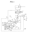
- FIG. 1 is a circuit diagram showing the basic configuration of a first embodiment of the present invention.
- a hydraulic drive system according to this embodiment comprises a hydraulic pump 1 of the variable displacement type having a swash plate 1a which constitutes displacement volume varying means, a hydraulic actuator 2 driven by a hydraulic fluid discharged from the hydraulic pump 1, a directional control valve 3 for controlling a flow of the hydraulic fluid supplied from the hydraulic pump 1 to the actuator 2, and a discharge control device 4 for controlling a flow rate of the hydraulic fluid discharged from the hydraulic pump 1.
- the discharge control device 4 comprises a drive cylinder unit, i.e.
- regulator 5 for driving a swash plate 1a of the hydraulic pump 1 to control the displacement volume
- load-sensing control device 6 for controlling operation of the regulator 5 to hold a differential pressure between a discharge pressure of the hydraulic pump 1 and a load pressure of the actuator 2 at a setting value, thereby controlling the discharge rate of the hydraulic pump 1.
- the regulator 5 comprises a piston member 7 linked with the swash plate 1a of the hydraulic pump 1 and having a larger-diameter pressure receiving portion 7a and a smaller-diameter pressure receiving portion 7b at the opposite ends, a first cylinder 8 into which is inserted the larger-diameter pressure receiving portion 7a of the piston member 7, and a second cylinder 9 into which is inserted the smaller-diameter pressure receiving portion 7b of the piston member 7.
- the second cylinder 9 is communi cated with a discharge line 11 for the hydraulic pump 1 through a line 10.
- the load-sensing control device 6 comprises a control valve 18 which includes a spring 12 for setting the differential pressure between the discharge pressure of the hydraulic pump 1 and the load pressure of the actuator 2, a drive part 14 supplied with the load pressure of the actuator 2 through a line 13, and a drive part 17 supplied with the discharge pressure of the hydraulic pump 1 through lines 15, 16.
- the force of the spring 12 is set to such a value that the differential pressure determined by the spring force becomes a level smaller than usual and suitable for the work which requires fine operation.
- the first cylinder 8 of the regulator 5 is connected to the control valve 18 through a line 19.
- the first cylinder 8 When the control valve 18 is at a left-hand position as viewed on the drawing sheet, the first cylinder 8 is communicated with a tank 21 through a line 20 so that the pressure in the first cylinder 8 becomes equal to a tank pressure. When the control valve 18 is at a right-hand position as viewed on the drawing sheet, the first cylinder 8 is communicated with the discharge line 11 through the lines 15, 10 so that the pressure in the first cylinder 8 becomes equal to the discharge pressure of the hydraulic pump 1.
- the first cylinder 8 When the control valve 18 is at an intermediate position, the first cylinder 8 is communicated with both the tank 21 and the discharge line 11 at the ratio corresponding to that position, so that the pressure in the first cylinder 8 becomes a some level between the tank pressure and the pump discharge pressure corresponding to the position of the control valve 18.
- the hydraulic drive system of the first embodiment further comprises an instruction unit 22 operated from the exterior for instructing a change in the differential pressure between the discharge pressure of the hydraulic pump 1 and the load pressure of the actuator 2, and a differential pressure setting device 23 capable of changing the setting value of the differential pressure in response to the instruction from the instruction unit 22.
- the differential pressure setting device 23 comprises a controller 24 for computing and outputting a control signal, and a control force applying device 25 for producing a control force responsive to the control signal and applying the control force to the control valve 18 on the side where the spring 12 is provided.
- the instruction unit 22 is connected to the controller 24, and so arranged as to output an instruction signal when operated by an operator.
- the instruction unit 22 is operated when instructing the differential pressure suitable for the ordinary work, and not operated when instructing the differential pressure smaller than usual and suitable for the work which requires fine operation.
- the controller 24 includes, as shown in Fig. 2, an input unit 26 for receiving the instruction signal from the instruction unit 22, a storage unit 27 for storing a differential pressure modifying value utilized to obtain a differential pressure target value suitable for the ordinary work, an arithmetic unit 28 for computing a control force corresponding to the differential pressure modifying value stored in the storage unit 27 in response to a signal output from the input unit 26, and an output unit 29 for outputting the control force computed by the arithmetic unit 28 as said control signal.
- the control force applying device 25 comprises a solenoid unit 30 for receiving the control signal from the output unit 29 of the controller 24, and a plunger 31 driven by the solenoid unit 30.
- the solenoid unit 30 Upon receiving the control signal, the solenoid unit 30 produces the control force computed by the arithmetic unit 28, the control force being transmitted to the control valve 18 through the plunger 31.
- an unload valve 32 which has a spring 33 for setting a minimum discharge pressure of the hydraulic pump 1 when the directional control valve 3 is at its neutral position.
- the load pressure is introduced through a line 34 to one end of the unload valve 32 on the same side as the spring 33, and the spring 33 is arranged to have a setting value somewhat larger than that of the spring 12 associated with the control valve 18.
- the hydraulic pump 1 is arranged such that when the swash plate 1a is at a minimum tilting position, the minimum discharge rate is ensured by an engine (not shown) set in operation.
- the minimum discharge rate produces a discharge pressure of the hydraulic pump 1 equal to the minimum discharge pressure determined by the unload valve 32.
- the minimum discharge pressure is introduced to the second cylinder 9 of the regulator 5.
- the minimum discharge pressure is also introduced to the drive part 17 of the control valve 18, so that the control valve 18 is driven into a state as shown in the right-hand position by overcoming the force of the spring 12, or the resultant of force of the spring 12 and control force from the control force applying device 25 when the latter is in operation.
- the hydraulic fluid is introduced from the hydraulic pump 1 to the actuator 2 through the directional control valve 3, whereupon the actuator 2 is driven to operate the working member (not shown).
- the load pressure is generated in the actuator 2 and then introduced to the drive part 14 of the control valve 18 so that the control valve 18 is driven into a state as shown in the left-hand position.
- the first cylinder 8 is thus communicated with the tank 21 to move the piston 7 of the regulator 5 leftward, as viewed on the drawing sheet, for increasing the discharge rate of the hydraulic pump 1.
- the discharge rate of the hydraulic pump 1 is controlled such that the differential pressure between the discharge pressure of the hydraulic pump 1 and the load pressure of the actuator 2 is held at a setting value determined by the force of the spring 12, or a setting value determined by both the force of the spring 12 and the control force from the control force applying device 25 when the latter is in operation.
- the differential pressure between the discharge pressure of the hydraulic pump 1 and the load pressure of the actuator 2 in the above operation process is set to a different value responsive to an instruction issued from the instruction unit 22 shown in Fig. 1 for modifying the differential pressure. This will now be described with reference to a flowchart of Fig. 3 showing the control sequence carried out by the arithmetic unit 28 of the controller 24.
- step S1 of Fig. 3 determines in step S1 of Fig. 3 whether the instruction signal is input from the instruction unit 22 to the arithmetic unit 28 through the input unit 26 of the controller 24. Since the instruction signal is input in this case, the above determination is responded by YES and the control goes to step S2.
- step S2 the differential pressure modifying value stored in the storage unit 27 is read out, in response to the instruction signal, into the arithmetic unit 28 in which the control force is computed corresponding to that differential pressure modifying value.
- the control then goes to step S3 where a control signal is output from the arithmetic unit 28 to the control force applying device 25.
- the control force applying device 25 shown in Fig. 1 is operated in response to the control signal, so that the plunger 31 pushes the end of the control valve 18 on the same side as the spring 12 with the control force computed by the arithmetic unit 28.
- the discharge rate of the hydraulic pump 1 is thus controlled such that the differential pressure between the discharge pressure of the hydraulic pump 1 and the load pressure of the actuator 2 becomes a setting value determined by the resultant of force of the spring 12 and control force applied from the control force applying device 25. Accordingly, the hydraulic fluid is discharged from the hydraulic pump 1 at a relatively large flow rate and then supplied to the actuator 2.
- operating the instruction unit 22 increases the differential pressure between the discharge pressure of the hydraulic pump 1 and the load pressure of the actuator 2, thereby enabling to perform the ordinary work in a conventional manner.
- the differential pressure is lowered so that the flow rate supplied to the actuator 2 at the same stroke of control lever as that in the ordinary work is reduced to facilitate operation of the actuator 2 at a finely adjusted speed for permitting fine operation with ease.
- the stroke of control lever S2 necessary for reaching a certain actuator speed when the instruction unit 22 is not operated is larger than the stroke of control lever S1 necessary for reaching a certain actuator speed when the instruction unit 22 is operated. Namely, the metering region in the former case becomes larger than that in the latter case, and this allows the operator to feel less fatigued during operation.
- the value obtained by subtracting the differential pressure target value, given by the setting value of the spring 12, from the differential pressure target value suitable for the ordinary work is stored, as the the differential pressure modifying value, in the storage unit 27 of the controller 24.
- the differential pressure target value suitable for the ordinary work is also possible to store the differential pressure target value suitable for the ordinary work as the the differential pressure modifying value, and then subtract the differential pressure target value, given by the setting value of the spring 12, from that stored value in the arithmetic unit.
- the second embodiment includes, similarly to the above first embodiment shown in Fig. 1, a discharge control device 41 comprising the regulator 5 and a load-sensing control device 40, and a differential pressure setting device 42 comprising the controller 24 and the control force applying device 25.
- a spring 44 of a control valve 43 which constitutes the load-sensing control device 40 and determines the differential pressure between the discharge pressure of the hydraulic pump 1 and the load pressure of the actuator 2, is set to provide such a spring force as producing the relatively large differential pressure suitable for the ordinary work.
- control force applying device 25 is arranged to apply the control force of the plunger 31 to the end of the control valve 43 on the side opposite to the spring 44, and the differential pressure modifying value stored in the arithmetic unit 27 (see Fig. 2) of the controller 24 is employed for obtaining the differential pressure target value suitable for the work which requires fine operation.
- the control force applying device 25 shown in Fig. 1 when the instruction unit 22 is not operated, the control force applying device 25 shown in Fig. 1 is also not operated. Therefore, the discharge rate of the hydraulic pump 1 is controlled to produce the large differential pressure balanced by the force of the spring 44, resulting in the relationship between the stroke of control lever and the actuator speed as indicated by the characteristic line a in Fig. 4.
- the control force applying device 25 is also operated, in a like manner to the first embodiment, to apply the control force in a direction opposite to the force of the spring 44 of the control valve 43.
- the discharge rate of the hydraulic pump 1 is thus controlled to produce the small differential pressure balanced by the difference between the force of the spring 44 and the control force, resulting in the relationship between the stroke of control lever and the actuator speed as indicated by the characteristic line b in Fig. 4.
- the second embodiment provides the differential pressure suitable for the ordinary work when the instruction unit 22 is not operated, whereas it provides the differential pressure suitable for the work which requires operation of the actuator 2 at a finely adjusted speed, when the instruction unit 22 is operated.
- the remaining operation and effect are the same as those in the first embodiment.
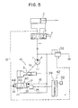
- the third embodiment is arranged to make control using electric signals obtained dependent on the differential pressure between the discharge pressure of the hydraulic pump 1 and the load pressure of the actuator 2.
- a discharge control device 50 comprises the regulator 5 and a load-sensing control device 51.
- the load-sensing control device 51 comprises a differential pressure sensor 52 for detecting the differential pressure between the discharge pressure of the hydraulic pump 1 and the load pressure of the actuator 2 and then outputting it in the form of an electric signal, a controller 53 for receiving the detected signal from the differential pressure sensor 52, two solenoid selector valves 54, 55 driven by control signals from the controller 53, and a hydraulic source 56.
- the solenoid selector valve 54 is disposed in a line 57 communicating between the first cylinder 8 and the second cylinder 9 of the regulator 5, whereas the solenoid selector valve 55 is disposed in a line 58 communicating the first cylinder 8 with the tank 21.
- the hydraulic source 56 is connected to the second cylinder 9 through a line 59.
- This embodiment also has the instruction unit 22 which is operated during the ordinary work as with the first embodiment, and which issues an instruction signal input to the controller 53.
- the controller 53 includes, similarly to the controller 24 in the first embodiment shown in Fig. 2, the input unit 26, the storage unit 27, the arithmetic unit 28 and the output unit 29.
- the storage units 27 stores therein a relatively large first differential pressure target value ⁇ P LS01 suitable for the ordinary work and a relatively small second differential pressure target value ⁇ P LS02 suitable for the special work which requires fine operation.
- the controller 53 serves also as differential pressure setting means capable of changing a setting value of the differential pressure responsive to an instruction from the instruction unit 22.
- step S12 reads the relatively large first differential pressure target value ⁇ P LS01 out of the differential pressure target values stored in the storage unit 27 of the controller 53 into the arithmetic unit 28, as a differential pressure target value ⁇ P LS0, followed by proceeding to step P13.
- the step P13 compares the differential pressure between the discharge pressure of the hydraulic pump 1 and the load pressure of the actuator 2 actually detected by the differential pressure sensor 52, i.e., differential pressure detected value ⁇ P LS, with the differential pressure target value ⁇ P LS0 in the arithmetic unit 28 of the controller 53. If these values are not equal to each other, the control goes to step S14.
- the step S14 determines whether or not the differential pressure detected value ⁇ P LS is larger than the differential pressure target value ⁇ P LS0. If so (YES), the control goes to step S15.
- the step S15 outputs control signals from the arithmetic unit 28 through the output unit 29, one of which turns off the solenoid selector valve 54 and the other of which turns on the solenoid selector valve 55, respectively.
- the solenoid selector valve 54 is held in a state as shown in Fig. 6, and the solenoid selector valve 55 is switched to a state as shown in the lower position for communicating the first cylinder 8 of the regulator 5 with the tank 21.
- the piston member 7 of the regulator 5 is now moved leftward, as viewed on the drawing sheet, under the hydraulic pressure of the hydraulic source.
- the discharge rate of the hydraulic pump 1 is controlled for being reduced such that ⁇ P LS becomes equal to ⁇ P LS0.
- step S16 If the determination of the step S14 indicated in Fig. 7 is responded by NO and the differential pressure detected value ⁇ P LS is smaller than the differential pressure target value ⁇ P LS0, the control goes to step S16.
- the step S16 outputs control signals from the arithmetic unit 28 through the output unit 29, one of which turns on the solenoid selector valve 54 and the other of which turns off the solenoid selector valve 55, respectively.
- the solenoid selector valve 55 is held in a state as shown in Fig. 6, and the solenoid selector valve 54 is switched to a state as shown in the lower position for communicating the hydraulic source 56 with both the first and second cylinders 8, 9 of the regulator 5.
- the piston member 7 of the regulator 5 is now moved rightward, as viewed on the drawing sheet, due to the difference in area between the larger-diameter pressure receiving portion 7a and the smaller-diameter pressure receiving portion 7b of the piston member 7.
- the discharge rate of the hydraulic pump 1 is controlled for being increased such that ⁇ P LS becomes equal to ⁇ P LS0. If ⁇ P LS is determined equal to ⁇ P LS0 in the step S13, the control returns to the start.
- the discharge rate of the hydraulic pump 1 is controlled to produce the differential pressure corresponding to the relatively large first differential pressure target value ⁇ P LS01, and the hydraulic fluid is supplied at the controlled flow rate from the hydraulic pump 1 to the actuator 2 through the directional control valve 3 for carrying out the ordinary work by the working member (not shown).
- the relationship between the stroke of control lever for the directional control valve 3 and the actuator speed as established in this case is similar to the above-mentioned characteristic line a shown in Fig. 4.
- step S17 reads the relatively small second differential pressure target value ⁇ P LS02 out of the differential pressure target values stored in the storage unit 27 of the controller 53 into the arithmetic unit 28, as a differential pressure target value ⁇ P LS0, followed by proceeding to step P13.
- the processing executed in the step 13 and the subsequent steps is the same as that in the above case, and hence the description is omitted here.
- the discharge rate of the hydraulic pump 1 is controlled to produce the differential pressure corresponding to the relatively small second differential pressure target value ⁇ P LS02, and the hydraulic fluid is supplied at the controlled flow rate from the hydraulic pump 1 to the actuator 2 through the directional control valve 3 for carrying out the work, which requires fine operation, by the working member (not shown).
- the relationship between the stroke of control lever for the directional control valve 3 and the actuator speed as established in this case is similar to the above-mentioned characteristic line b shown in Fig. 4.
- the third embodiment can also make smaller the ratio of a change in the actuator speed to the stroke of control lever for the directional control valve 3 during the special work which requires fine operation. Accordingly, the actuator 2 can be operated at a finely adjusted speed with ease, while allowing the operator to feel less fatigued.
- the present invention provides advantageous effects of permitting to carry out the ordinary work usually performed by hydraulic machines mounting thereon the hydraulic drive system of the present invention, and easily realize operation of the actuator at a finely adjusted speed for carrying out the work which requires fine operation with ease, while allowing the operator to feel less fatigued.
Applications Claiming Priority (2)
| Application Number | Priority Date | Filing Date | Title |
|---|---|---|---|
| JP159221/88 | 1988-06-29 | ||
| JP15922188 | 1988-06-29 |
Publications (2)
| Publication Number | Publication Date |
|---|---|
| EP0349092A1 true EP0349092A1 (de) | 1990-01-03 |
| EP0349092B1 EP0349092B1 (de) | 1993-02-24 |
Family
ID=15688981
Family Applications (1)
| Application Number | Title | Priority Date | Filing Date |
|---|---|---|---|
| EP89201734A Expired - Lifetime EP0349092B1 (de) | 1988-06-29 | 1989-06-28 | Hydraulisches Antriebssystem |
Country Status (4)
| Country | Link |
|---|---|
| US (1) | US5085051A (de) |
| EP (1) | EP0349092B1 (de) |
| KR (2) | KR920010875B1 (de) |
| DE (1) | DE68904998T2 (de) |
Cited By (5)
| Publication number | Priority date | Publication date | Assignee | Title |
|---|---|---|---|---|
| EP0443561A1 (de) * | 1990-02-22 | 1991-08-28 | Brueninghaus Hydromatik Gmbh | Vorrichtung zum Verstellen des Verdrängervolumens einer hydrostatischen Maschine |
| EP0563514A1 (de) * | 1992-03-28 | 1993-10-06 | O&K ORENSTEIN & KOPPEL AG | Lastdruckunabhängige, hydraulische Antriebsvorrichtung für Arbeitsgeräte an Baumaschinen |
| CN102588359A (zh) * | 2012-02-28 | 2012-07-18 | 上海中联重科桩工机械有限公司 | 液压系统、挖掘机及液压系统的控制方法 |
| DE102014004337A1 (de) | 2013-03-28 | 2014-10-02 | Aebi Schmidt Deutschland Gmbh | Kommunalfahrzeug |
| EP2759712A4 (de) * | 2011-09-21 | 2015-11-11 | Sumitomo Heavy Industries | Hydraulische steuerungsvorrichtung und hydraulisches steuerverfahren |
Families Citing this family (28)
| Publication number | Priority date | Publication date | Assignee | Title |
|---|---|---|---|---|
| US5279122A (en) * | 1989-08-16 | 1994-01-18 | Kabushiki Kaisha Komatsu Seisakusho | Hydraulic circuit apparatus for supplying fluid under pressure into hydraulic cylinders for work implement |
| JP2520314B2 (ja) * | 1990-01-18 | 1996-07-31 | 株式会社小松製作所 | 油圧掘削機の走行速度切換装置 |
| US5174114A (en) * | 1990-02-28 | 1992-12-29 | Hitachi Construction Machinery Co., Ltd. | Hydraulic drive system for construction machine |
| DE69112375T2 (de) * | 1990-09-28 | 1996-03-07 | Hitachi Construction Machinery | Steuerungssystem für hydraulische pumpe. |
| JP3064574B2 (ja) * | 1991-09-27 | 2000-07-12 | 株式会社小松製作所 | 油圧掘削機における作業油量切換制御装置 |
| WO1994023213A1 (en) * | 1993-03-26 | 1994-10-13 | Kabushiki Kaisha Komatsu Seisakusho | Controller for hydraulic drive machine |
| US5560205A (en) * | 1994-12-21 | 1996-10-01 | Caterpillar Inc. | Attenuation of fluid borne noise |
| US5758499A (en) * | 1995-03-03 | 1998-06-02 | Hitachi Construction Machinery Co., Ltd. | Hydraulic control system |
| JP2701812B2 (ja) * | 1995-10-30 | 1998-01-21 | 石川島播磨重工業株式会社 | 冷水塔の冷却ファン液圧駆動制御装置 |
| DE19834955B4 (de) * | 1998-08-03 | 2008-02-07 | Linde Material Handling Gmbh | Hydrostatisches Antriebssystem |
| US6874318B1 (en) * | 2003-09-18 | 2005-04-05 | Sauer-Danfoss, Inc. | Automatic remote pressure compensation in an open circuit pump |
| US6945335B2 (en) * | 2003-10-06 | 2005-09-20 | Komatsu Ltd. | Oil-pressure controlling device for earthmoving machine |
| DE102004061555A1 (de) * | 2004-12-21 | 2006-06-22 | Bosch Rexroth Aktiengesellschaft | Hydraulische Steueranordnung |
| DE102008054876A1 (de) | 2008-12-18 | 2010-07-01 | Deere & Company, Moline | Hydrauliksystem |
| DE102008054880A1 (de) | 2008-12-18 | 2010-07-01 | Deere & Company, Moline | Hydrauliksystem |
| JP5956184B2 (ja) * | 2012-02-27 | 2016-07-27 | 株式会社小松製作所 | 油圧駆動システム |
| DE102012207422A1 (de) * | 2012-05-04 | 2013-11-07 | Robert Bosch Gmbh | Hydraulische Steueranordnung mit Lastdruckminderungund hydraulischer Ventilblock dafür |
| DE102013216395B4 (de) | 2013-08-19 | 2019-01-17 | Danfoss Power Solutions a.s. | Steuereinrichtung für hydraulische verstellpumpen und verstellpumpe mit einer steuereinrichtung |
| EP3311034B1 (de) | 2015-06-16 | 2019-11-13 | Volvo Construction Equipment AB | Lastmessendes hydrauliksystem für eine arbeitsmaschine |
| JP6747746B2 (ja) | 2016-09-16 | 2020-08-26 | 日立オートモティブシステムズ株式会社 | 可変容量ポンプ及び内燃機関の作動油供給システム |
| JP6715216B2 (ja) * | 2017-06-22 | 2020-07-01 | 日立オートモティブシステムズ株式会社 | 可変容量形ポンプ及びその制御方法 |
| CN109441906B (zh) * | 2018-12-27 | 2020-05-08 | 上海航天控制技术研究所 | 一种电液比例负载敏感泵及泵阀联合控制伺服系统 |
| EP3770428B1 (de) | 2019-07-26 | 2023-04-19 | Robert Bosch GmbH | Hydraulische druckmittelversorgungsanordnung für eine mobile arbeitsmaschine und verfahren |
| DE102019219206A1 (de) | 2019-07-26 | 2021-01-28 | Robert Bosch Gmbh | Hydraulische Druckmittelversorgungsanordnung, Verfahren und mobile Arbeitsmaschine |
| DE102019212845A1 (de) | 2019-07-26 | 2021-01-28 | Robert Bosch Gmbh | Hydraulische Druckmittelversorgungsanordnung und Verfahren |
| DE102019219451A1 (de) | 2019-07-26 | 2021-01-28 | Robert Bosch Gmbh | Hydraulische Druckmittelversorgungsanordnung für eine mobile Arbeitsmaschine und Verfahren |
| US11680381B2 (en) | 2021-01-07 | 2023-06-20 | Caterpillar Underground Mining Pty. Ltd. | Variable system pressure based on implement position |
| US11661723B1 (en) | 2021-12-28 | 2023-05-30 | Caterpillar Underground Mining Pty. Ltd. | Variable system pressure based on implement position |
Citations (2)
| Publication number | Priority date | Publication date | Assignee | Title |
|---|---|---|---|---|
| US4282898A (en) * | 1979-11-29 | 1981-08-11 | Caterpillar Tractor Co. | Flow metering valve with operator selectable boosted flow |
| US4487018A (en) * | 1982-03-11 | 1984-12-11 | Caterpillar Tractor Co. | Compensated fluid flow control |
Family Cites Families (6)
| Publication number | Priority date | Publication date | Assignee | Title |
|---|---|---|---|---|
| DE2754430A1 (de) * | 1977-12-07 | 1979-06-13 | Bosch Gmbh Robert | Steuereinrichtung fuer mindestens zwei verstellbare pumpen |
| US4292805A (en) * | 1979-09-24 | 1981-10-06 | Rexnord Inc. | Servo-valve convertible construction |
| DE3071998D1 (en) * | 1980-09-12 | 1987-09-03 | Caterpillar Inc | Horsepower consumption control for variable displacement pumps |
| US4523430A (en) * | 1981-03-19 | 1985-06-18 | Daikin Kogyo Co., Ltd. | Fluid flow control system |
| JPS58174707A (ja) * | 1982-04-06 | 1983-10-13 | Daiden Kk | 複数機器油圧駆動回路 |
| DE3321483A1 (de) * | 1983-06-14 | 1984-12-20 | Linde Ag, 6200 Wiesbaden | Hydraulische einrichtung mit einer pumpe und mindestens zwei von dieser beaufschlagten verbrauchern hydraulischer energie |
-
1989
- 1989-06-23 KR KR1019890008792A patent/KR920010875B1/ko not_active Application Discontinuation
- 1989-06-26 KR KR1019890008792A patent/KR900003545A/ko not_active IP Right Cessation
- 1989-06-28 US US07/373,337 patent/US5085051A/en not_active Expired - Lifetime
- 1989-06-28 DE DE8989201734T patent/DE68904998T2/de not_active Expired - Lifetime
- 1989-06-28 EP EP89201734A patent/EP0349092B1/de not_active Expired - Lifetime
Patent Citations (2)
| Publication number | Priority date | Publication date | Assignee | Title |
|---|---|---|---|---|
| US4282898A (en) * | 1979-11-29 | 1981-08-11 | Caterpillar Tractor Co. | Flow metering valve with operator selectable boosted flow |
| US4487018A (en) * | 1982-03-11 | 1984-12-11 | Caterpillar Tractor Co. | Compensated fluid flow control |
Non-Patent Citations (1)
| Title |
|---|
| PATENT ABSTRACTS OF JAPAN, vol. 8, no. 12 (M-269)[1449], 19th January 1984; & JP-A-58 174 707 (DAIDEN K.K.) 13-10-1983 * |
Cited By (8)
| Publication number | Priority date | Publication date | Assignee | Title |
|---|---|---|---|---|
| EP0443561A1 (de) * | 1990-02-22 | 1991-08-28 | Brueninghaus Hydromatik Gmbh | Vorrichtung zum Verstellen des Verdrängervolumens einer hydrostatischen Maschine |
| EP0563514A1 (de) * | 1992-03-28 | 1993-10-06 | O&K ORENSTEIN & KOPPEL AG | Lastdruckunabhängige, hydraulische Antriebsvorrichtung für Arbeitsgeräte an Baumaschinen |
| EP2759712A4 (de) * | 2011-09-21 | 2015-11-11 | Sumitomo Heavy Industries | Hydraulische steuerungsvorrichtung und hydraulisches steuerverfahren |
| US9651061B2 (en) | 2011-09-21 | 2017-05-16 | Sumitomo Heavy Industries, Ltd. | Hydraulic control apparatus and method |
| CN102588359A (zh) * | 2012-02-28 | 2012-07-18 | 上海中联重科桩工机械有限公司 | 液压系统、挖掘机及液压系统的控制方法 |
| CN102588359B (zh) * | 2012-02-28 | 2014-10-22 | 上海中联重科桩工机械有限公司 | 液压系统、挖掘机及液压系统的控制方法 |
| DE102014004337A1 (de) | 2013-03-28 | 2014-10-02 | Aebi Schmidt Deutschland Gmbh | Kommunalfahrzeug |
| DE102014004337B4 (de) | 2013-03-28 | 2023-04-27 | Aebi Schmidt Deutschland Gmbh | Kommunalfahrzeug sowie Verfahren zur Einstellung von Pumpenausgangsdrücken einer Verstellpumpe |
Also Published As
| Publication number | Publication date |
|---|---|
| KR900003545A (ko) | 1990-03-26 |
| DE68904998T2 (de) | 1993-08-26 |
| EP0349092B1 (de) | 1993-02-24 |
| US5085051A (en) | 1992-02-04 |
| KR920010875B1 (ko) | 1992-12-19 |
| KR910000503A (ko) | 1991-01-29 |
| DE68904998D1 (de) | 1993-04-01 |
Similar Documents
| Publication | Publication Date | Title |
|---|---|---|
| EP0349092A1 (de) | Hydraulisches Antriebssystem | |
| JP2657548B2 (ja) | 油圧駆動装置及びその制御方法 | |
| EP1553231B1 (de) | Steuervorrichtung einer Hydraulikantriebsmaschine | |
| EP0376295B1 (de) | Hydraulische Steuerregelungsvorrichtung für Baumaschinen | |
| EP0681106A1 (de) | Hydraulische vorrichtung für ein arbeitsgerät | |
| US5267440A (en) | Hydraulic control system for construction machine | |
| JP3510114B2 (ja) | 作業機の制御方法およびその制御装置 | |
| EP2098437B1 (de) | Lenksystem für ein nutzfahrzeug | |
| EP2123541A1 (de) | Lenksystem für ein nutzfahrzeug | |
| US7007466B2 (en) | System and method for controlling hydraulic flow | |
| GB2261962A (en) | Automatic relative control of construction vehicle actuators. | |
| US6560962B2 (en) | Control system of a hydraulic construction machine | |
| EP0439621B1 (de) | Zufuhrschaltungsvorrichtung für öl unter druck zum hydraulischem kolben einer baustellenvorrichtung | |
| JPH1061604A (ja) | 建設機械の油圧駆動装置及びその制御方法 | |
| JP2784198B2 (ja) | 土木・建設機械の油圧駆動装置 | |
| EP0440807A1 (de) | Hydraulische antriebsvorrichtung für zivilbauausrüstung | |
| JP3491940B2 (ja) | 可変容量型油圧ポンプの制御装置 | |
| US6459976B1 (en) | Method and system for controlling steady-state speed of hydraulic cylinders in an electrohydraulic system | |
| JPH08219107A (ja) | 油圧機械の油圧再生装置 | |
| KR100433186B1 (ko) | 굴삭기의 엔진과 펌프의 출력 자동 제어 시스템 | |
| JPH11350538A (ja) | 油圧駆動機械の制御装置 | |
| JP3175992B2 (ja) | 油圧駆動機械の制御装置 | |
| JPH07139509A (ja) | 油圧作業機の油圧駆動装置 | |
| JPH06249208A (ja) | 建設機械の油圧駆動装置 | |
| JPH04250227A (ja) | 建設機械の油圧駆動装置 |
Legal Events
| Date | Code | Title | Description |
|---|---|---|---|
| PUAI | Public reference made under article 153(3) epc to a published international application that has entered the european phase |
Free format text: ORIGINAL CODE: 0009012 |
|
| AK | Designated contracting states |
Kind code of ref document: A1 Designated state(s): DE FR GB IT SE |
|
| 17P | Request for examination filed |
Effective date: 19900703 |
|
| 17Q | First examination report despatched |
Effective date: 19901130 |
|
| GRAA | (expected) grant |
Free format text: ORIGINAL CODE: 0009210 |
|
| AK | Designated contracting states |
Kind code of ref document: B1 Designated state(s): DE FR GB IT SE |
|
| REF | Corresponds to: |
Ref document number: 68904998 Country of ref document: DE Date of ref document: 19930401 |
|
| ET | Fr: translation filed | ||
| ITF | It: translation for a ep patent filed |
Owner name: MODIANO & ASSOCIATI S.R.L. |
|
| PLBE | No opposition filed within time limit |
Free format text: ORIGINAL CODE: 0009261 |
|
| STAA | Information on the status of an ep patent application or granted ep patent |
Free format text: STATUS: NO OPPOSITION FILED WITHIN TIME LIMIT |
|
| 26N | No opposition filed | ||
| EAL | Se: european patent in force in sweden |
Ref document number: 89201734.4 |
|
| REG | Reference to a national code |
Ref country code: GB Ref legal event code: IF02 |
|
| PGFP | Annual fee paid to national office [announced via postgrant information from national office to epo] |
Ref country code: IT Payment date: 20080625 Year of fee payment: 20 |
|
| PGFP | Annual fee paid to national office [announced via postgrant information from national office to epo] |
Ref country code: DE Payment date: 20080703 Year of fee payment: 20 Ref country code: SE Payment date: 20080609 Year of fee payment: 20 |
|
| PGFP | Annual fee paid to national office [announced via postgrant information from national office to epo] |
Ref country code: FR Payment date: 20080617 Year of fee payment: 20 |
|
| PGFP | Annual fee paid to national office [announced via postgrant information from national office to epo] |
Ref country code: GB Payment date: 20080702 Year of fee payment: 20 |
|
| REG | Reference to a national code |
Ref country code: GB Ref legal event code: PE20 Expiry date: 20090627 |
|
| EUG | Se: european patent has lapsed | ||
| PG25 | Lapsed in a contracting state [announced via postgrant information from national office to epo] |
Ref country code: GB Free format text: LAPSE BECAUSE OF EXPIRATION OF PROTECTION Effective date: 20090627 |